HAL Id: cea-01174196
https://hal-cea.archives-ouvertes.fr/cea-01174196
Submitted on 8 Jul 2015HAL is a multi-disciplinary open access archive for the deposit and dissemination of sci-entific research documents, whether they are pub-lished or not. The documents may come from teaching and research institutions in France or abroad, or from public or private research centers.
L’archive ouverte pluridisciplinaire HAL, est destinée au dépôt et à la diffusion de documents scientifiques de niveau recherche, publiés ou non, émanant des établissements d’enseignement et de recherche français ou étrangers, des laboratoires publics ou privés.
Copyright
STeP : AN INNOVATIVE TELEOPERATION SYSTEM
FOR DECOMMISSIONING OPERATIONS
J.M. Goubot, Philippe Garrec
To cite this version:
J.M. Goubot, Philippe Garrec. STeP : AN INNOVATIVE TELEOPERATION SYSTEM FOR DE-COMMISSIONING OPERATIONS. Decommissioning challenges: An industrial reality ?, French Nu-clear Energy Society, SFEN, Paris; International Atomic Energy Agency, Vienna; OECD NuNu-clear Energy Agency, Nov 2003, Avignon, France. �cea-01174196�
STeP : AN INNOVATIVE TELEOPERATION SYSTEM FOR DECOMMISSIONING OPERATIONS
J.M Goubot (CEA), P Garrec (CEA) ABSTRACT
Decommissioning tasks in laboratories or interim storage facilities may be complicated by poor accessibility and by the diversity of operations that must be carried out. This is particularly true of waste storage shafts that are often accessible only from above and are relatively limited in size compared with existing intervention systems. This article describes the issues involved and the studies that have been carried out to develop a force-feedback Shaft Teleoperation system (STeP). Following a discussion of a range of possible concepts and of the preliminary tests carried out to define the system architecture and functions, the specifications and expected performance of the specially developed master-slave system are described. An example of a waste retrieval application is then presented with emphasis on the tools used and the full-scale mockup that will be built.
RÉSUMÉ
Les tâches d’assainissement dans les laboratoires ou les installations d’entreposage sont parfois rendues délicates par le manque d’accessibilité ou la diversité des actions à mener. C’est le cas notamment des puits d’entreposage de déchets qui ne possèdent souvent qu’un accès par le dessus et dont la dimension peut être assez faible au regard des équipements d’intervention existants.
Cet article décrit la problématique et les études qui ont été menées pour la réalisation d’un Système de Téléopération en Puits (STeP) à retour d’effort. Dans un premier temps sont abordés les différents concepts possibles et les essais préliminaires ayant permis de définir l’architecture et les fonctionnalités du système. Les spécifications et les performances attendues du système maître-esclave développé spécialement sont ensuite décrites. Un exemple d’application concernant la reprise de déchets est finalement présenté en insistant plus particulièrement sur les outils utilisés et le maquettage préalable à échelle 1 qui sera mené.
INTRODUCTION
The Shaft Teleoperation system was developed as part of a project to propose generic equipment for retrieval of waste placed in interim storage shafts under a wide range of conditions: physical nature, conditioning and packaging. Preliminary studies conducted on behalf of three CEA facilities identified dozens of wasteforms to be recovered. They were classified according to their physical nature: liquid, flowable solid, solid and type of package. The studies concluded that a generic device was required with an effective teleoperation system allowing it to adapt more easily than a specialized machine to the wide range of tasks to be carried out.
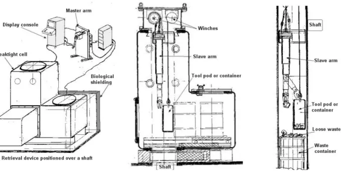
Figure 1 shows the main system components including the SteP slave arm inserted vertically into the shaft from which the waste will be retrieved.
Figure 1 : Conceptual design of the retrieval system (specification stage)
Seeking to identify the most pertinent concept to perform the required tasks in a shaft environment involved CAD studies to determine the optimum arm architecture, and testing of existing equipment to validate the concept and identify the main system characteristics.
CAD optimization of the slave arm
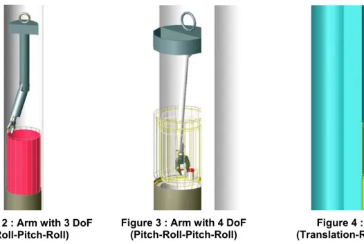
The optimization phase consisted in determining the most suitable arm linkage for working in a cylindrical (shaft) environment with the minimum number of degrees of freedom, while maintaining acceptable dexterity. The initial work showed that all the tasks could not be performed using only an arm and gripper: some operations require the use of tools such as a power screwdriver, suction device, container, etc. In order to meet the generic device requirement, we chose to use tool pods with the slave arm and gripper to implement the onboard process. This arrangement (Figure 1) led us to design slave arms occupying only part of the shaft (Figures 2 to 4).
Figure 2 : Arm with 3 DoF
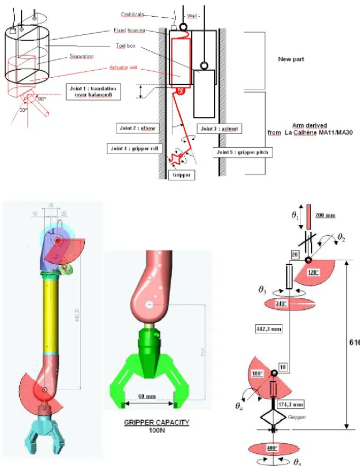
(Roll-Pitch-Roll) Figure 3 : Arm with 4 DoF (Pitch-Roll-Pitch-Roll) (Translation-Roll-Pitch-Pitch-Roll) Figure 4 : Arm with 5 DoF
The small shaft diameter (less than 380 mm) and the packages that must be accessible to the gripper led us to favor cable actuation technology with remote drive motors in the arm representation. An arm with 3 DoF (Figure 2) does not provide sufficient dexterity to orient the gripper; an arm with 5 DoF (Figure 4) has suitable dexterity but the limited length of the second arm segment makes it difficult to control the gripper height. We therefore continued our simulations with the 4-DoF version (Figure 3), which provides the optimum tradeoff between degrees of freedom and dexterity.
Figure 5 : Installing a handling rod Figure 6 : Recovery of a vessel from a waste container
Figures 5 and 6 show that the arm linkage and dexterity are well suited to the shaft environment. Concept validation tests
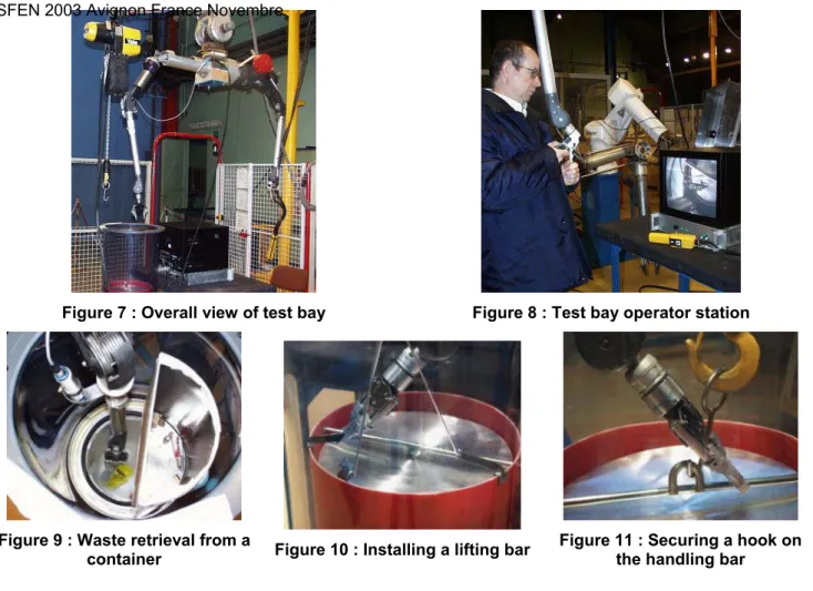
We carried out several concept validation tests using a La Calhène MA11-C wall-mounted telemanipulator arm. Two of the 6 DoF of this arm were temporarily immobilized to ensure representative test conditions. A camera was mounted on the arm and various tasks were performed to assess the contribution of force feedback.
Figure 7 : Overall view of test bay Figure 8 : Test bay operator station
Figure 9 : Waste retrieval from a
container Figure 10 : Installing a lifting bar Figure 11 : Securing a hook on the handling bar
The tests confirmed that the concept of a slave arm based on a wall-mounted telemanipulator kinematic was an applicable solution. However, we noted that it was frequently necessary to raise and lower the arm, and therefore we decided to add an additional translation DoF.
The very cramped environment made it very difficult to mount the camera so as to provide a satisfactory view of the workspace. As such, we installed the camera axially above the arm which allows a 2D view of the workspace. The force-feedback teleoperation system compensates for the viewing deficiencies and allows tasks to be accomplished with considerable dexterity.
STEP SPECIFICATIONS
Our review of the state of the art of teleoperated systems did not identify any satisfactory solutions fulfilling the abaove requirements; we therefore decided to pursue a specific development program using the existing “technological building blocks” developed by the CEA (LIST/DRT/DTSI/SRSI):
- an electric master arm developed and distributed by Haption: the Virtuose 6D 4040 arm, - a TAO 2000 teleoperation control and display system,
- components from existing wall-mounted telemanipulators,
- ballscrew actuator technology and drive cable developed for the Virtuose 6D 4040 master arm. The main development specifications are indicated below:
- master arm including a control unit for the slave arm and tool pod winches, for controlling the tools and standard teleoperation functions,
- 5-DoF slave arm + gripper with force feedback, - arm load capacity: 100 N in any position,
- arm including a nuclear camera (bi-unit hard radiation tolerant camera), lighting system and microphone,
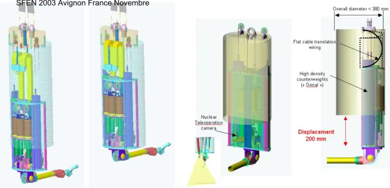
- very compact slave arm, both vertically (the drive unit is about 600 mm high) and occupying only a half-cylinder less than 375 mm in diameter,
- design objectives: 1000-hour MTBF and capability of withstanding a cumulative irradiation dose of approximately 50 kGy.
STEP DESCRIPTION System
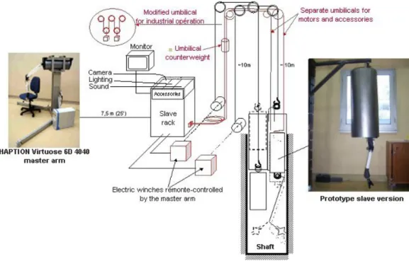
The teleoperation system comprises a slave arm and a master arm, each with its own control rack. The arms are connected by fiber optics. The master arm and the master and slave control racks are installed at a distance from the shaft.
Figure 12 – General scheme for laboratory testing (prototype)
The system uses force feedback and is based on a computerized teleoperation architecture in which the coupled master and slave arms have different kinematics. The slave control rack and slave arm are connected via an umbilical operated with the hoist and fitted with a counterweight to maintain the umbilical taut at all times and allow automatic return travel. The slave arm controlled by a separate control rack connected to the master arm. The rack comprises a PC, speed variators and utility functions.
Master arm
The master arm is the Virtuose 6D 4040 industrial model.
The 6-axis cable-driven arm includes a tool jaw control grip (conventional arm). The actuator technology is new and distinguishes the Virtuose 6D master arm from all master arms marketed to date (patent EUR 01938347.0-2421-FR0101630). Force feedback is provided on each axis. It is supplied with a standard control rack including a PC, speed variators and utility functions.
Figure 14 - Virtuose 6D 4040 Haption ball-screw/cable actuators
Figure 15 –Virtuose 6D 4040 Haption master arm - Geometrical specifications
The working volume is a cube 400 mm on a side. The control grip guarantees 135° rotation within the working volume on all the edges of the cube.
Slave system Arm
The slave arm fits inside the leaktight enclosure and is positioned in the shaft by a dedicated winch. A separate adjacent hoist is used to move tools into reach of the slave arm for the retrieval operations. The slave arm is also used to grasp tools suspended from the auxiliary hoist by means of a multipurpose gripper.
Figure 16 – Slave arm working volume and specifications
The slave arm has five degrees of freedom in addition to closing the gripper, with force feedback on each axis. The arm does not include a rotation control on the drum centerline (shaft centerline). The arm components (clevis, tube, toggle joint) are based on the original parts of the second segment of the La Calhène MA 11 (or MA30) telemanipulators. The segment was shortened to fit the working volume of the waste shaft and the overall height of the machine. The gripper is derived from a standard model produced by SIT.
The operational linear travel rate of the slave arm gripper is the same as that of the master arm control grip, or about 1 m/s.
Drive unit
The slave actuator technology adopts with few modifications the principle of the highly reversible ballscrew system with cable transmission to the control axes used on mechanical telemanipulators (the technology of the Virtuose 6D 4040 master arm). This compact and robust principle uses only proven industrial components. The linear arrangement of the actuators and the use of brushless pancake motors (concentric actuators) allows all 6 actuators to fit into the required semicylindrical volume. The motors complied with inert gas operation. The relative position of the rotor is measured by a pancake resolver concentric with the motor centerline. The overall design benefits from operating experience with MA 23 machines (CEA/Cybernetix) and MA 11 telemanipulators (CEA/La Calhène) and from manufacturing methods developed by the aeronautical industry for crimped cable transmission systems.
Figure 17 – Translation kinematics
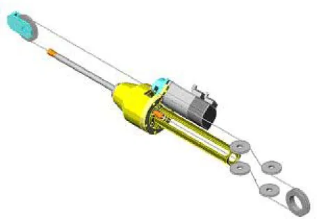
Figure 18 – Slave actuator unit of the prototype
Figure 19 - CAD view of prototype actuator pod (compact industrial version on the right)
Other equipment
The drive unit design allows for the dimensions of a bi-unit hard radiation tolerant camera and includes spotlights to illuminate the work zone. The slave arm also includes a microphone to reproduce process noise. The umbilical is designed to support its own weight augmented by the tensile load of the automatic winding mechanism. It is 10 m long and specially designed to obtain a very small bend radius to limit the overall height when the slave arm is retracted.
CAT (Computer-Aided Teleoperation) functionalities
The control software is a simplified version of TAO 2000 V1 meeting the specification requirements. CAT functions include:
- master-slave force-feedback coupling on all axes - adaptable to for alternate kinematics
- constant, modifiable load and position homothetic ratios - master-slave offset function
- coupling-decoupling, pause-resume function - slave arm initializing mode (relative sensors)
- software diagnostics: measurement of position and load parameters, hardware fault detection and tracing (motors, resolvers, variators).
EXAMPLES
Various legacy waste retrieval tasks were considered, and appropriate tool pods were design and built (Figures 20 to 25). All tool pods are standardized with regard to the outer shell; they are fully adaptable to the process used with the slave arm.
Figure 20 : Loose waste retrieval pod
Figure 21 : Pod for installing a lifting bar using threaded
anchoring points
Figure 22 : Pod for installing and removing the screw-on cover of
Figure 23 : Powder vacuuming
pod Figure 24 : Tool for recovery of irregular-shaped objects Figure 25 : Tool for recovery of small flat objects
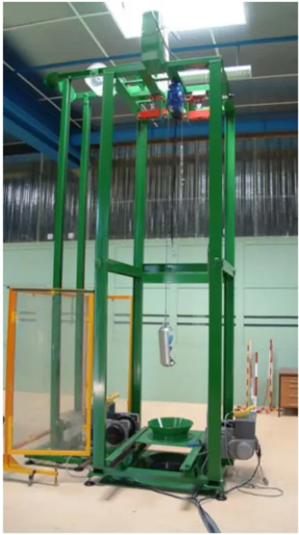
Teleoperation system and tool pod qualification tests are scheduled for the end of this year. Figures 26 and 27 show the test facility that will be used for this purpose.
Figure 26 : Mockup of an interim storage shaft Figure 27 : STeP operating test jig
CONCLUSION
The Shaft Teleoperation system is a teleoperation system specifically designed for working inside shafts, cells, or other environments accessible from above. Its compact design (363 mm diameter) allows access to dry interim storage shafts.
The TAO 2000 teleoperation control and display system allows all-axis position and load control together with useful basic functions: position offset between master and slave arms, different position and load ratios, arm balancing, and the possibility of placing the operator station up to several hundred meters from the slave arm. The system teleoperating performance is excellent, at least equivalent to the La Calhène MA23 system.
STeP uses mechanical components (MA11 and MA30) of proven reliability, and endurance testing confirmed the reliability of the new cable and ballscrew transmission system. The tool pod concept allows the system to perform a wide range of tasks.
The system is currently at the pre-industrial prototype stage; functional validation trials are scheduled for the end of 2003 within the scope of the application example mentioned above.