Controlled Synthesis of Magnetic Particles
bySU KYUNG SUH
B.S. Chemical Engineering, Pohang University of Science and Technology, South Korea (2005) M.S. Chemical Engineering Practice, Massachusetts Institute of Technology (2008)
Submitted to the Department of Chemical Engineering in partial fulfillment of the requirements for the degree of
Doctor of Philosophy in Chemical Engineering at the
MASSACHUSETTS INSTITUTE OF TECHNOLOGY December 2011
@ 2011 Massachusetts Institute of Technology. All rights reserved.
Signature of ~MASSACHUSEfS INSTITUTE MsOF TECHNOLCf'Y
FEB
0
8
2012
BRARI ES
ARCHIVES
Author...Department of Chemical Engineering
n f - December, 2011
Certified by... -.... ... T. Alan Hatton Ralph Landau Professor of Chemical Engineering Practice Thesis Supervoor Certified by... Profess Accepted by... Patrick S. Doyle or of Chemical Engineering Thesis Supervisor William M. Deen Carbon P. Dubbs Professor of Chemical and Biological Engineering Chairman, Committee for Graduate Students
Abstract
Controlled Synthesis of Magnetic Particles
by Su Kyung Suh
Submitted to the Department of Chemical Engineering on December 12', 2011, in partial fulfillment of the requirements for the degree of
Doctor of Philosophy in Chemical Engineering Practice
Magnetic particles have been used for many applications demanding a broad range of particles morphologies and chemistries. Superparamagnetism is advantageous over ferromagnetism because it enables us to control and recover magnetic nanoparticles during and after chemical processing. Superparamagnetic particles have an oriented magnetic moment under a magnetic field but lose this behavior in the absence of a field. Ferromagnetic materials can be superparamagnetic when they consist of a single size domain, which is on the order of 10s of nanometers. However, since the magnetic force is proportional to the volume of the particle, one needs to apply higher gradient of magnetic field to recover smaller particles. Therefore, large particles are preferred for easy manipulation using external forces. For this reason, the synthesis of large, superparamagnetic particles is very important and is desirable for future applications. The purpose of this work is (1) to examine the three synthesis methods of superparamagnetic units, (2) to understand the behavior of particles created using these methods as well as the synthesis mechanisms, and (3) to investigate the potential applications of these particles.
Large paramagnetic particles can be made by assembling superparamagnetic nanoparticles. We developed a method for the process-dependent clustering of monodisperse magnetic nanoparticles using a solvent evaporation method from solid-in-oil-in-water (S/O/W) type emulsions. When polymers that are incompatible with the nanoparticle coatings were included in the emulsion formulation, monolayer- and multilayer-coated polymer beads and partially coated Janus beads were prepared. The precise
number of nanoparticle layers depended on the polymer/magnetic nanoparticle ratio in the oil droplet phase parent emulsion. The magnetic nanoparticle superstructures responded to the application of a modest magnetic field by forming regular chains with alignment of nonuniform structures (e.g., toroids and Janus beads) in accordance with theoretical predictions and with observations in other systems.
In addition, we synthesized non-spherical magnetic microparticles with multiple functionalities, shapes and chemistries. Particle synthesis is performed in two steps; polymeric microparticles homogenously functionalized with carboxyl groups were generated AA % using stop-flow lithography, and then in situ co-precipitation was
used to grow magnetic nanoparticle at these carboxyl sites. With successive growth of magnetic nanoparticles, we obtained polymeric particles with saturations magnetization up to 42 emu per gram of microparticle, which is significantly greater than what can be obtained commercially. We also investigated the physical properties of magnetic nanoparticles grown in polymeric microparticles, and provide an explanation of the properties.
Lastly, we used experimentation and modeling to investigate the synthesis of opaque microparticles made via stop-flow lithography.
Opaque magnetic beads incorporated into hydrogel microparticles
during synthesis changed the height and the degree of cross-linking of the polymer matrices formed. The effect of the concentration of the opaque material on the particle height was determined experimentally, and agreed well with model predictions based on the photo-polymerization process over a wide range of UV absorbance. We also
created particles with two independent anisotropies, magnetic and geometric, by applying magnetic fields during particle synthesis. Our work provides a platform for rational design of lithographic patterned opaque particles and also a new class of structured magnetic microparticles.
Overall, this work demonstrates three strategies for creating magnetic substrates containing superparamagnetic nanoparticles and characterization of their resulting properties.
Thesis Supervisor: T. Alan Hatton
Title: Ralph Landau Professor of Chemical Engineering Practice Thesis Supervisor: Patrick S. Doyle
Acknowledgments
Completing a Ph.D. degree is one of the biggest achievements in my life. It could not be finished without other's help. First, I would like to thank my advisors, Professor Hatton and Professor Doyle, for consistent support and direction. Without your confidence in me, I could not write this at this moment. Alan - thank you for your guidance, and for showing me how to put creativity into science. Pat - thank you for teaching me how to think problems logically and critically. Also, I would like to thank to my committee members, Prof. Love, Prof. Olsen, and Prof. Stellacci, for insights and helpful discussions. I would like to acknowledge Singapore-MIT Alliance for the generous funding and support to the projects.
I loved being a Hatton group member. Tatsushi - I enjoyed very much to work with you. You taught me many experimental skills and how to structure scientific problems. Fei - thank you for not only giving me a lot of scientific assistance but also cheering me up. I felt like having my older brother in my office. Ying - thank you for countless discussions and conversations over past five years. Asha, Kristin, Abhinav, Huan, and Smeet - thank you for being great neighbors in my office. Because of you, I could enjoy spending time every day. Nate, Emily, and Mike
-thank you for being great safety managers.
There are many Doyle group members who have been helpful during my Ph.D. Rilla - thank you for working with me for magnetic micro particle project. I am so glad we finally made this project worked. Kai - thank you for making so many particles without any complaint. You are the greatest UROP I have ever met. Bong - thank you for initiating the opaque particle project.
Steve - thank you for your help about bioassays. Jason, Harry, Rathi, Matt, and Nakwon- thank you for your support especially when my experiment did not work.
Outside of Hatton and Doyle groups, I would like to thank Prof. van der Sande for discussions about TEM images. Dr. Chu, Dr. Yong, and Mr. Boisver - thank you for teaching me how to use equipments in DMSE centers. Suzanne, Katie and Joel, thank you for providing administrative helps.
Table of Contents
C hapter Introduction ... 17
1.1 M agnetic particles...17
1.2g p ... 18
1.3 Properties of m agnetic particles... 19
1.3.1 Dom ains...19
1.3.2 Hysteresis...20
1.3.3 Stability requirem ents...21
1.3.4 M agnetization ... 22
1.3.5 Relaxation...22
1.4 Importance of large magnetic units with superparamagnetism ... 23
1.5 Current methods to create bigger magnetic units...24
1.5.1 Assem blies of m agnetic nanoparticles... 24
1.5.2 Polym er tem plated m agnetic particles ... 25
1.6 Research overview ... 27
Chapter 2 Controlled synthesis of magnetic nanoparticle clusters... 31
2.1 Introduction... 31
2.2 Experim ental setup ... 32
2.2.1 M aterials ... 32
2.2.2 Synthesis of m agnetic nanoparticles...:... 32
2.2.3 Clustering of m agnetic nanoparticles... 34
2.2.4 M agnetic nanoparticle coated polystyrene beads ... 34
2.2.5 Characterizations... 34
2.2.6 Pervaporation ... 35
2.3 Result and discussions ... 36
2.3.1 M agnetic nanoparticles ... 36
2.3.2 Clusters of m agnetic nanoparticles ... 37
2.3.3 M agnetic nanoparticle coated polym er beads... 40
2.3.4 Assemblies of magnetic clusters and magnetic particle coated PS... 41
2.3.5 Evaporation using the pervaporation unit ... 42
2.4 Conclusion ... 44
2.5 References... 45
Chapter 3 In-situ co-precipitation of magnetic nanoparticles in microgels... 47
3.1 Introduction... 47
3.2 Experim ental m ethod... 48
3.2.1 M aterials ... 48
3.2.2 M icrofluidic fabrication... 48
3.2.3 Stop-flow-lithography setup ... 48
3.2.4 Polym eric particle synthesis ... 49
3.2.5 In-situ m agnetic nanoparticle synthesis ... 49
3.2.6 Characterizations... 49
3.3 Results and discussion ... 50
3.3.1 Non spherical m agnetic m icroparticles... 50
3.3.2 Successive creation of magnetic nanoparticles in microparticles... 52
3.3.3 M agnetic properties ... 53
3.3.4 Size distribution of m agnetic nanoparticles... 56
3.3.5 Contents of iron oxide... 57
3.4 Conclusion ... 60
Chapter 4 Modeling and synthesis of opaque microparticles ...
63
4.1 Introduction...---... --... 63 4.2 Experimental methods ... 64 4.2.1 M aterials ...---. ---... ... 64 4.2.2 M icrofluidic devices ... 65 4.2.3 Stop-Flow-Lithography setup... 65 4.2.4 Particle synthesis ... 65 4.2.5 UV Absorbance measurement... 664.2.6 Particle Height M easurement... 67
4.2.7 M agnetic characterization... 67
4.3 M odelp ...-.---. . -... 67
4.3.1 Governing equations ... 67
4.3.2 Boundary and Initial Conditions... 70
4.3.3 Numerical solution... 70
4.4 Results and discussion... 73
4.4.1 Synthesis of opaque particles... 73
4.4.2 M odeling result with various value of P ... 73
4.4.3 Comparison of experimental data and modeling results... 75
4.4.4 Particle synthesis under uniform magnetic field... 78
4.5 Conclusion...---... ---... 81
4.6 Reference...83
Chapter
5
Magnetic particles for enhanced biomolecule detection...87
5.1 Introduction...87 5.2 Experiment methods...89 5.2.1 M aterials ...---.---... 89 5.2.2 M icrofluidic devices ... 89 5.2.3 Stop-Flow-Lithography setup ... 90 5.2.4 W ashing scheme... 91
5.2.5 miRNA incubation experiments ... 91
5.2.6 W ell experiments... .. ... 92
5.2.7 M agnetic tweezer experiment ... 93
5.3 Results and discussion... 94
5.3.1 pH enhanced washing... 94
5.3.2 miRNA detection...---... ---... 96
5.3.3 M agnetic particles in microwells... 98
5.3.4 Selective recovery of particles using m agnetic tweezer ... 100
5.5 Reference ... 104
Chapter 6 Conclusion and outlook...
107
6.1 Clusters of magnetic nanoparticles ... 108
6.2 Non-spherical magnetic microparticles ... 109
6.3 Opaque particles... 111
List of Figures
Figure 1-1: Properties of magnetic particles that enable many applications ... 18 Figure 1-2: Domain structure for single crystal and polycrystalline. Dashed lines represent domain walls, while solid lines are crystal walls 12... 19
Figure 1-3: Hysteresis circle of a multi-domain magnetic particles and domain wall 12
displacem ent in such a m aterial. ... 20 Figure 1-4: Examples of nanoparticle assemblies. Controlling amount of ligands 28, interaction
of ligands 34 or using emulsions 19, nanoparticles can be assembled to bigger units... 25
Figure 1-5: Magnetic particles generated with polymer templates. Menager et al. performed
27 2
emulsion polymerizations in the presence of magnetic nanoparticles . Yang et al. and Zhang
et al. 23 reported in-situ synthesis of magnetite in polymeric particles... 26
Figure 2-1: Temperature control to create monodisperse magnetic nanoparticles... 33 Figure 2-2: Schematic of the synthesis procedure for the preparation of magnetic nanoparticle clu sters. ... 33 Figure 2-3: Pervaporation unit. At the center, the unit has 120 fibers with a diameter of 300 ptm.
... 3 5 Figure 2-4: TEM images of magnetic nanoparticles and their characterization. (a) TEM images
of magnetic nanoparticles (b) HR-TEM showing atomic planes of nanoparticles (c) HR-TEM showing stabilizers OA/OAm (d) FTIR measurement (e) TGA measurement. ... 36
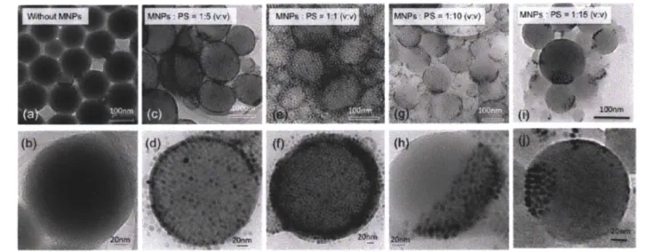
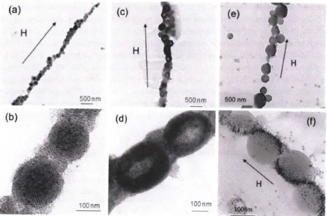
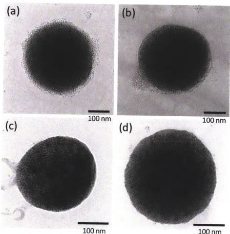
Figure 2-5: Magnetic nanoparticle clusters: (a) TEM image of a single-domain crystalline superlattice formed at low temperature (25 *C), (b) fast Fourier transform diffraction pattern for particles in (a) showing BCC (110) structure, (c) TEM image of a multidomain crystalline superlattice formed at intermediate temperatures (50 *C), (d) TEM image of amorphous cluster formed at higher temperatures (60 *C), and (e) TEM image and (f) SEM image of toroidal structures formed at 80 *C, above the solvent boiling point. The TEM image in (e) was paired with an image of the same cluster tilted at an angle of 300 for stereoscopic visualization to show that the toroidal aggregates have a true doughnut-like structure... 38 Figure 2-6: Nanoparticle lattice mirrors molecular ordering. (a) TEM image of nanoparticle clusters (b) HR-TEM image of magnetic nanoparticles. Inset image is from (a)... 39 Figure 2-7: Magnetic nanoparticle coated polymer bead. (a, b) beads without nanoparticles, (c, d) monolayer-coated beads, (e, f) bilayer-coated beads, (g-j) Janus beads with different surface coverages depending on the initial nanoparticle/polystyrene ratio. In (g)-(j), the solvent used was a mixture of hexane and chloroform ... 40 Figure 2-8: Nanowire with clusters under magnetic field: (a, b) crystalline superlattices, (c, d) toroidal clusters, and (e, f) Janus beads. ... 42 Figure 2-9: TEM images of clusters obtained for processing times of 20, 40, 60 and 180 minutes respectively. The surfaces become less diffuse with longer contact times as the clusters are dried more thoroughly. Scale bars are 100nm . ... 43
Figure 3-1: Schematics showing the synthesis process. ... 50 Figure 3-2: Optical images of various magnetic microparticles. (a) Homogenous magnetic disks. (b) Homogenous tranglular particles. (c) Janus disks (d) Gradient particles... 51 Figure 3-3: Successive synthesis of magnetite in micro polymer particles... 53 Figure 3-4: Magnetic properties of magnetic micro particles and nanoparticles. (a)
Magnetization curves. The points were obtained from SQUID measurement, while solid lines were calculated using Chantrell's method shown in equation (6). The dotted line was obtained from the Langevin function assuming that particles were monodisperse. (b) Saturation
magnetization values of polymer/nanoparticle complexes. (c) Magnetic nanoparticle content excluding the polymer matrix calculated using results panel (b) and TGA analysis. The ratios
XFe304XPEG/PAA and XFe2O3/XpEG/pM are plotted. (d) Nanoparticle sizes calculated using Chantrell's
m eth od ... 55 Figure 3-5: Cross-sectional TEM images of magnetite/polymer matrix. Magnetic nanoparticles in polymeric particles after (a) the first cycle and (b) the fourth cycle... 57 Figure 3-6: The mechanism of the synthesis. (a) Schematics to explain the synthesis mechanism. The ratio between Fe and Fe ions in bulk is different from that in the polymer matrix. (b) SEM image of PAA/PEG particles. (c) The particle in (b) imaged at low magnification. (d) PAA/PEG/Iron oxide particle surfaces. (e) The particle in (d) imaged at low magnification... 59
Figure 4-1: Schematic diagram of a microfluidic channel for measurements of relative UV ab sorbance... 66 Figure 4-2: Schematic diagram of a microfluidic channel for stop-flow lithography in the
presence of opaque m aterials ... 71 Figure 4-3: (a) Bright-field image of a 4-inlet microfluidic channel having 0, 25, 50 and 75 mg/ml magnetic bead monomer solutions. (b) Side-view of a particle synthesized in the channel depicted in (a). (c) Fluorescent side-view image of a particle created with a UV absorbing dye (Allura Red AC), where the pre-polymer solutions contained 0, 9, 18, 27 mg/ml of dye labeled 1, 2,3, 4 on the particle respectively. (d) Fluorescent beads with an excitation wavelength of 360 nm and an emission wavelength of 407 nm were spread on the top of channel. The UV projected from the objective passes through the monomer solutions to excite the blue bead-coated substrate and the emission from the beads travels back through the sample where it is then captured by the objective for detection. The light intensity from the fluorescent beads depends on the
concentration of magnetic beads in the channel. ... 72 Figure 4-4: Uncross-linked monomer concentration (4) profile between the bottom (r9 = 0) and the top (il = 1) of the channel for various values of
P
(0.017, 0.17, 0.34, 0.51, 0.68, 0.85, 1.0). These results were obtained numerically by solving equations (9) and (10)... 74 Figure 4-5: Comparison of experimental data and modeling results. Dimensionless particle height y (scaled by channel height) versus UV absorbance j. Dotted line is from simulations. Solid squares and open triangles are from experiments using magnetic beads and UV absorbing dye, respectively. ... 75 Figure 4-6: The relative, background-subtracted UV absorbance for the magnetite and opaque dye solutions tested... 76 Figure 4-7: Comparison of experimental data and modeling results. Cross-linked oligomer concentration (1- 4, shown as dotted lines and acquired from simulation) versus dimensionless height in channel T). Right axis and solid curves show for comparison the fluorescent signals across the g-direction as acquired from particles synthesized in the presence of UV absorbing d y e ... 7 7 Figure 4-8: Particles synthesized in the presence of an external magnetic field. (a) A uniform magnetic field was applied just before UV exposure to form chained magnetic beads. Although the chains absorb UV, microparticles can be created due to polymerization reaction nearby the chains (shown schematically as purple in the image). (b) Top-view of the microfluidic channel with 25 mg/ml magnetic beads during the synthesis. The inset image is a washed particle after the synthesis. (c) Particles with magnetic chains embedded. A uniform magnetic field was applied to conveniently observe the side of particles. (d), (e) Magnified image of the circled part of (c), (f) respectively. (f) Particles with 25 mg/ml magnetic beads synthesized with no magnetic field present. (g-h) Illustration of particle alignments under the magnetic field. The particle in (g) contains chained magnetic beads while the particle in (h) has embedded magnetic beads with a random distribution... 79Figure 5-1: Schematic overview of the miRNA assay... 91 Figure 5-2: Schematic description showing patterned substrate with subsequent addition and manipulation of magnetic particles into microwells... 92 Figure 5-3: The magnetic tweezer set-up on the microscope stage. The tip was dipped in the
solution when current was sent through the coil... 93 Figure 5-4: Demonstration of pH-enhanced rinsing. The high pH solution decomposes ester groups to carboxyl and alcohol groups. Optical images of magnetic barcode particles after rinsed with pH 8, 12, and 14 solutions, respectively. The scale bar is 50 m... 94 Figure 5-5: Schematic of polymer saponification with high pH... 95 Figure 5-6: miRNA detection using magnetic barcode particles after high-pH rinsing. (a)
Fluorescent images of control particle with no magnetic material (b), a particle with a magnetic code (c), and a particle with magnetic code and magnetic probe, all shown after a miRNA assay. (d) Fluorescent signal from miRNA detection after scanning in a flow-through device. The error bars represent intra-run standard deviation... 96 Figure 5-7: Patterning of the magnetic barcode particles in microwells using a hand magnet. (a) Fluorescent images of microwells occupied with the two types of magnetic particles. (b)
Statistics of well occupancy with magnetic (red) and non-magnetic (blue) barcoded particles... 98 Figure 5-8: Usage of magnetic particles in microwells. (a) Particles were located in wells. (b) Wells were covered with cover-glass. (c) Cover-glass was removed while magnet attracted particles at the bottom of w ells ... 99 Figure 5-9: Selective collection of magnetic particles using a magnetic tweezer. (a) Fluorescent image of microwells filled with two types of particles with corresponding bright-field image (b). (c) Fluorescent image of microwells shown in (c) after removing particles with code 103 using the magnetic tweezer. (d) Bright field image of (c)... 100 Figure 5-10: The set-up shown in Figure 5-3 was rotated 90 degree to observe vertical forces exerted on magnetic particles. The magnetic force was measured using drag force on magnetic b ead s. ... 10 1 Figure 5-11: Average magnetic force exerted on one magnetic bead and average velocity as a function of distance from the tweezer tip. ... 101
Figure 6-1: TEM images of gold nanoparticle and Janus particles... 109 Figure 6-2: Schematic diagram of pervaporation modules used to obtain Janus type clusters. 109 Figure 6-3: Procedure to create magnetic particles functionalized with DNA. The optical images show gradient magnetic particles before and after second functionalization... 110 Figure 6-4: Chaining of magnetic bead under uniform magnetic field during polymerization of particles. The optical image shows created particles using the described method... 111 Figure 6-5: Assemblies of hydrogel particles containing magnetic chain under a uniform
List of Tables
Table 2-1. Zeta potential and DLS... 41
Table 4-1: Simplified reaction mechanism in our model... 67
Table 4-2: Parameters used in this paper... 70
Table 4-3: Measured particle heights... 76
Table 4-4: UV absorbance information from literature. UV absorbance depends on the size, nanoparticle concentration, and wavelength... 81
Chapter 1
Introduction
The work written in this thesis involves three strategies for creating magnetic substrates containing superparamagnetic nanoparticles and characterization of their resulting properties. Magnetic particles have been used for many applications; to meet application broad range of needs, various types of particles morphologies and chemistries are desired. This chapter outlines (1) the usages of magnetic particles, (2) principles of magnetic particles, and (3) importance of larger magnetic units for various applications.
1.1
Magnetic particles
Magnetic particles are of increasing interest in chemical processes, due to their potential use in various fields, such as separations 1-3, catalysis4, analysis5 and diagnostics.: These applications
are enabled by the ability to manipulate the particles under external magnetic fields, transfer energy selectively to magnetic particles using oscillating magnetic field, and to have large surface to volume ratio by reducing the size of magnetic particles, as shown in Figure 1-1. Because of these attributes, magnetic particles are an ideal model for controllable substrates.
Surface area/ volume Magnetic field Energy
* Magnetic particles
Figure 1-1: Properties of magnetic particles that enable many applications
1.2
Wide usage of magnetic particles
The most common application of magnetic particles is the separation of materials from complex
2-3,6
mixtures. The method of high gradient magnetic separation (HGMS) involves two successive processes, using special magnetic particles that have tuned adsorptive properties. HGMS is performed by attaching an adsorbent, which can selectively capture desired chemicals to the surface of magnetic nanoparticles. After the absorption, one can recover the magnetic particles and adsorbed molecules with a magnetic field. The recovered particles can be used several times, reducing the cost of the process.
Magnetic nanoparticles have been studied extensively for biomedical applications such as magnetic hyperthermia, and magnetic resonance imaging (MRI). Magnetic hyperthermia is a new type of cancer treatment which has several advantages over other therapies. As magnetic particles can absorb and release energy depending on the conditions of the magnetic field they are subjected to, they can be used to control local temperature using external oscillating fields. This property enables us to increase the temperature of specific locations within human body. In the presence of magnetic particles, magnetic particles have been used to increase the temperature tumor cells, either killing the cells or making them vulnerable.
Magnetic particles can also be used as contrast agents. MRI is an imaging process for clinical diagnostics, measuring the magnetization of protons in water via time-varying magnetic fields. Different tissues have different water concentrations, creating contrast in imaging. The addition of magnetic nanoparticles in targeted area can either enhance or reduce this contrast to improve imaging for a desired area.8 9
Magnetic nanoparticles are also an attractive platform for ultra-high density information storage. The self assembly properties of magnetic nanoparticles can produce patterned media, which are required for digital data storage. The magnetic moment of each particle can have a different orientation, storing 1 bit.'0
In theory, storage media utilizing 10 nm-sized particles could have a storage capacity of about 1 terrabyte/in2 .
1.3 Properties of magnetic particles
Magnetic particles exhibit unique properties. This section will describe a few basic theories about magnetization of superparamagnetic materials. Most information explained below is adapted from Rosensweig' book.'2
1.3.1 Domains
Magnetic solids contain domains, which are defined by as regions of uniform magnetization. Each domain, in which the electric dipoles of all of the atoms are oriented in the same direction, is separated from other domains by a domain wall. As illustrated in Figure 1-2, crystals can have more than one domain.
Figure 1-2: Domain structure for single crystal and polycrystalline. Dashed lines represent domain walls, while solid lines are crystal walls 12
Magnetic materials create domains to minimize the field energy, AEMs, but they cannot make infinite number of domains because the generation of domain walls requires a certain amount of energy, EDw. Magnetostatic energy, AEMS, is proportional to the volume of the particles, while
domain wall energy increases proportionally to the area of domain walls. For small particles, the energy cost of making domain walls is greater than the magnetostatic energy reduction caused by
their creation; therefore, they have only a single domain. The maximum single domain particle size is called the critical diameter and occurs when AEMs = EDw. The critical diameter can be expressed as follows,
AK
D, ~18 eff
,aoM2
where A is the exchange constant, Keff is the anisotropy constant, [o is the permeability of free space and M is the saturation magnetization. 12-13
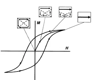
1.3.2 Hysteresis
Figure 1-3: Hysteresis circle of a multi-domain magnetic particles and domain wall displacement in such a material. 12
When a magnetic field is applied to single crystal particles with multiple domains, they initially exhibit domain displacement as shown in Figure 1-3, where H is the magnetic field strength and M is intensity of magnetization. This corresponds to the arrow starting from origin in Figure 1-3.
After magnetic saturation of the particles, particles will still exhibit some magnetization even if the magnetic field is reduced to back to zero. This offset amount is called the retentivity or remanence. This behavior, ferromagnetism, is an example of hysteresis and can be observed in particles with multiple domains. The existence of hysteresis is not preferred for applications requiring precise control of magnetic particles. Single domain magnetic particles, termed
superparamagnetic materials, do not exhibit hysteresis, making them advantageous for such applications.
1.3.3 Stability requirements
Magnetic fluids are colloidal single phase dispersions that respond rapidly to external forces due to their short time and length scales for equilibration. For colloidal magnetic fluids, colloid stability should be considered carefully depending on the application. Magnetic particles having long chain molecules on their surface are more stable than those without such stabilizers. They prevent van der Waals attraction via steric repulsion. The stabilizers are usually chosen to have similar properties to the surrounding fluid. The stability of the colloidal particle suspension is affected by various energies, including thermal, magnetic, gravitational, dipole-dipole contact and dipole fluctuation energies. The expressions for these energies are the following, where k is Boltzmann's constant, L is the elevation in the gravitational field, A is the Hamaker constant, 1 is surface-to-surface separation distance between particles over radius of particles.
Thermal energy = kT
Magnetic energy = pOMHV
Gravitational energy = ApVgL
Dipole - dipole contact energy =-poM 2V 12
A 2 2 12 +41
Dipole fluctuation energy = - 6 l241
r
++4n-
(1+22
(1+2)2Considering the stability against settling of particles, particles will prefer to be separated, rather than aggregated, in field-free space when:
thermal energy _ kT magnetic energy poMHV
The above equation is equivalent to following criterion:
d (6kT /,cpOMH)"3 (1-2)
At room temperature, Fe304 is known to be stable when d
<
8.1 nm according to the equationabove. The relative stability of magnetic fluids against other forces can be calculated similarly using the previous equation with the energy expressions given. Also, the dipole fluctuation
energy equation indicates that prevention of contact is important. Steric hindrance of stabilizers can block the particle contact.
1.3.4 Magnetization
In the absence of a magnetic field, the magnetic moment of each particle is oriented randomly. Thus, the average magnetization is zero. However, magnetic moments start aligning with as a magnetic field is and thermal energy is overcome. The torque density acting on magnetic moments in a magnetic field can be expressed as
r = mH sin 0 (1-3)
where m is the magnetic dipole moment and 0 is the angle between the applied magnetic field and magnetic moment. The expended energy to rotate particles from an initial angle to 0 requires integration from 0 to 0,
0
W =JMOd=mH (I- Cos 0) (1-4)
The Boltzmann distribution assumes that the probability of a given state is proportional to e-WAT
when the associated energy of that state is W. Therefore, average magnetization is,
() mcosexp(mH cos / kT)sin d6
Sfexp(mH cos0 / kT) sin d(
After this integration, the resulting relationship is
M 1
$Md
a
where
#
is the volume fraction of magnetic solids in the fluid, Md is the saturation magnetization of the bulk material, a = ntoMHd3/6kT and L(a) is denoted as the Langevin function. Thisrelationship describes the magnetization of non-interacting superparamagnetic particles, displaying saturated curves at high field strengths and a linear region in low fields.12
1.3.5 Relaxation
Since magnetic nanoparticles are used for many applications, it is important to understand the properties of relaxation. There are two magnetization relaxation mechanisms acting on colloidal ferrofluids in the presence of a change in applied field. They are Brownian relaxation and Neel relaxation. The rotation of particles in the fluid produces Brownian relaxation, which has a characteristic rotational diffusion time, TB, of,
rB = 3Vrj
I kT
(1-7)where r/o is the viscosity of the carrier fluid. Neel relaxation is the rotation of the magnetic moment vector within the particle, independent of any particle movement. The Neel relaxation characteristic time, rN, iS
1
(KfV~
TN = -exp (1-8)
f
kT)where fo is a frequency, approximately 109 Hz. When KeffV << kT, the energy barrier for moment rotation is much smaller than the thermal energy, and thus the moment can be flipped easily by thermal energy.
In the case where rN << rB, relaxation is governed by Neel relaxation process and the material is considered to exhibit intrinsic superparamagnetism. For the opposite case, the relaxation is dominated by the Brownian mechanism and the material is said to possess extrinsic
superparamagnetism.12,14
1.4 Importance of large magnetic units with superparamagnetism
As we discussed above, superparamagnetism is advantageous over ferromagnetism because it enables us to control and recover magnetic nanoparticles during and after chemical processing. Superparamagnetic particles have an oriented magnetic moment under a magnetic field but lose this behavior in the absence of a field. Ferromagnetic materials can be superparamagnetic when they have single size domain, namely, small particle size (-20 nm).12 However, since the
magnetic force is proportional to the volume of the particle, one needs to apply higher gradient of magnetic field to recover smaller particles. Therefore, large particles are more easily manipulated by external forces than are small particles. In this situation, synthesis of large, superparamagnetic particles is very important and is desirable for future applications. Therefore,
ability to create large magnetic units would provide large improvements in the performance over the previously mentioned materials.2
1.5 Current methods to create bigger magnetic units
Large paramagnetic particles can be made by assembling superparamagnetic nanoparticles, or by dispersing such magnetic nanoparticles throughout a unit's matrix. The first approach utilizes the clustering of nanoparticles, which can be achieved via self assembly of nanoparticles 15-17 or by using emulsions as templates.18-19 Depending on the application, further coating or functionalization can be achieved. Clusters can be cores or shells. 20- The second approach relies
on the incorporation of nanoparticles within porous structures. Magnetic nanoparticles can be
22-24 25-27
grown or entrapped in polymer matrices. While magnetic nanoparticle clusters tend to exhibit higher saturation magnetization than polymer-based paramagnetic particles due to higher magnetic material density, polymer substrates provide great flexibility in terms of chemical functionality and mechanical properties.
1.5.1 Assemblies of magnetic nanoparticles
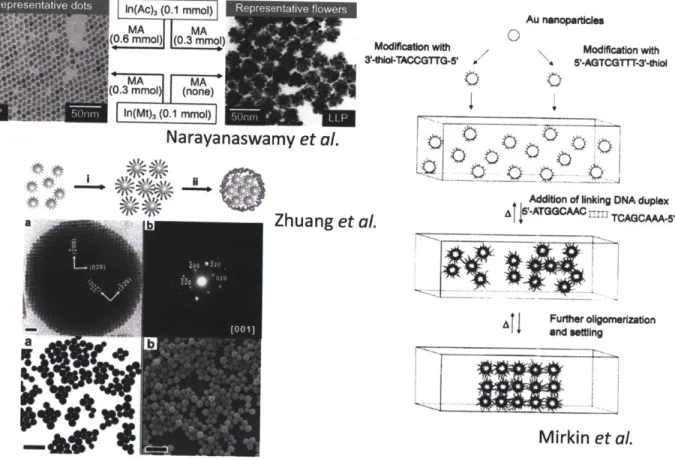
Initially, assemblies of metallic nanoparticles were investigated when developing methods to stabilize nanoparticles in solutions in order to prevent aggregation. In the absence of ligands, nanoparticles tend to form clusters spontaneously, which is energetically favorable. With sufficient amounts of ligand, nanoparticles tend to stay as discrete particles, while those with less ligand aggregate to form clusters.15,28-30 Furthermore, many research groups have used chemical or physical forces between ligands such as hydrogen bonding3 1, dipole interaction
32, or electrostatic forces3 3
in order to build interesting structures. For example, gold nanoparticles coated with single stranded DNA can be built to structures via interaction with complementary DNA as shown in Figure 1-4.34
Another method for assembly involves the use of templates. Emulsions are one example. When emulsions contain magnetic nanoparticles, they separate nanoparticles from the continuous phase. 16,18-19,35 The discontinuous phase, containing the nanoparticles, can be concentrated to
form nanoparticle clusters. This method can be applied to various metallic and non-metallic nanoparticles. The main advantage is that emulsion based self-assembly can be applied to a broad range of particles, with no chemistry dependence so long as the particles can be contained within emulsions. Using solid-in-oil-in water emulsions as a colloidal template, one can precisely control the clusters as shown in Figure 1-4.
Au nwnopaes
In(Ac)a (0,1nmol) Re presntatwve flower,
=MA MA (0.6 mmol) (0.3 mmol) -MA MA (0.3 mmol) (none)
In(Mt)
(0.1 mmow
a
Narayanaswamy et al. 1Zhuang et
Modification with Modification with
3-thiol-TACCGTrG-5 '-AGTCGTTT-thioI
Addition of linking DNA duplex
5
I&-ATGGCAAC1 TCAGCAAA-5
al.j
41
and settlingFurther olgomerizationMirkin et al.
Figure 1-4: Examples of nanoparticle assemblies. Controlling amount of ligands 28, interaction of ligands 34 or using emulsions 19, nanoparticles can be assembled to bigger units.
1.5.2 Polymer templated magnetic particles
When using the bottom-up methods for cluster formation described in the previous section, it is difficult to create micron-scale clusters with well-controlled structure. For this reason, various techniques to include nanoparticles in bigger polymer particles have been explored. Preformed magnetic nanoparticles can be embedded in polymer particles to create structural hierarchy. In one example, magnetic nanoparticles were mixed into monomer solutions, such that during polymer particle formation via polymerization, the nanoparticles were entrapped.24-2 5,2 7,3 6
37-38
Another approach is to absorb nanoparticles into swollen polymeric matrices. Typically, polymers attract nanoparticles via electrostatic interactions. However, these techniques that
aO 0
utilize preformed nanoparticles are not readily compatible with high nanoparticle loadings, often resulting in nanoparticle aggregation.39
4e
- m
Menager et
a/.
Impregnation
Ferri Oleate Fe3O4 Nanoparticles
Thermolysis
Deswelling
Yang et al.
Zhang et al.
OH-
Mev+
Figure 1-5: Magnetic particles generated with polymer templates. Menager
et al. performed emulsion polymerizations in the presence of magnetic
nanoparticles 2. Yang et al. 26 and Zhang et al. 23 reported in-situ synthesis
of magnetite in polymeric particles.
One of the approaches to overcome the challenge of high nanoparticle loading is to use in-situ magnetic nanoparticle synthesis within polymer matrices. Ugelstad et al. have reported magnetic nanoparticle precipitation in the pores of swollen polystyrene microspheres.22 For hydrophilic
magnetic particles, cationic polymers were utilized as templates to attract ferrous or ferric ions in the particles.23 4 0 Using these templates, the precipitation of magnetic nanoparticles in polymer
were performed using external stimuli, temperature and pH. Many of these methods are used to create commercially-available beads used in biomedical applications.
1.6 Research overview
The purpose of this work is to examine the three synthesis methods of superparamagnetic units, to understand the behavior of particles created using these methods as well as the synthesis mechanisms, and to investigate the potential applications of these particles. The organization of this work is following:
Chapter 2 describes clustering superparamagnetic nanoparticles into controlled structures. Chapter 3 explains in-situ precipitation of magnetic nanoparticles in polymeric microparticles.
Chapter 4 describes the polymerization of hydrogel particles in the presence of magnetic beads and the development of a mathematicl model of the process.
Chapter 5 discusses potential application of the magnetic particles created using these methods for biomolecule detection and building secondary structures.
1.7 Reference
(1) Miltenyi, S.; MUller, W.; Weichel, W.; Radbruch, A. Cytometry 1990, 11, 231. (2) Bucak, S.; Jones, D. A.; Laibinis, P. E.; Hatton, T. A. Biotechnol Progr 2003, 19, 477.
(3) Ditsch, A.; Lindenmann, S.; Laibinis, P. E.; Wang, D. I. C.; Hatton, T. A. Ind Eng
Chem Res 2005, 44, 6824.
(4) Stevens, P. D.; Fan, J.; Gardimalla, H. M. R.; Yen, M.; Gao, Y. Organic Letters 2005, 7, 2085. (5) (6) (7) (8) R198. (9) 36, R167. (10) (11) (12) 1997. (13) (14) (15) (16) (17) (18) Peng, Q.; Li, (19) 14166. 2516. 4194.
Gupta, A. K.; Gupta, M. Biomaterials 2005, 26, 3995.
Miltenyi, S.; Muller, W.; Weichel, W.; Radbruch, A. Cytometry 1990, 11, 231. Mornet, S.; Vasseur, S.; Grasset, F.; Duguet, E. J Mater Chem 2004, 14, 2161. Berry, C. C.; Curtis, A. S. G. Journal of Physics D: Applied Physics 2003, 36, Pankhurst,
Q.
A.; Connolly, J.; Jones, S. K.; Dobson, J. J Phys D Appl Phys 2003, Ross, C. Annual Review of Materials Research 2001, 31, 203.Zhou, H.; Narayan, J. J Nanopart Res 2006, 8, 595.
Rosensweig, R. E. Ferrohydrodynamics; Dover Publications: Mineola, N.Y., Lu, A. H.; Salabas, E. L.; Schuth, F. Angew Chem Int Edit 2007, 46, 1222.
Frenkel, J. The kinetic theory of liquids; Dover: New York, 1955.
Ditsch, A.; Laibinis, P. E.; Wang, D. I. C.; Hatton, T. A. Langmuir 2005, 21, 6006. Ge, J.; Hu, Y.; Yin, Y. Angewandte Chemie 2007, 119, 7572.
Lattuada, M.; Hatton, T. A. JAm Chem Soc 2007, 129, 12878.
Bai, F.; Wang, D.; Huo, Z.; Chen, W.; Liu, L.; Liang, X.; Chen, C.; Wang, X.;
Y. Angewandte Chemie International Edition 2007, 46, 6650.
Zhuang, J.
Q.;
Wu, H. M.; Yang, Y. A.; Cao, Y. C. J Am Chem Soc 2007, 129, (20) Shang, H.; Chang, W. S.; Kan, S.; Majetich, S. A.; Lee, G. U. Langmuir 2006, 22, (21) Lambert, E. M.; Viravaidya, C.; Li, M.; Mann, S. Angewandte Chemie 2010, 122, (22) Stenstad, P.; (23) (24) (25) (26)Ugelstad, J.; Berge, A.; Ellingsen, T.; Schmid, R.; Nilsen, T. N.; Mork, P. C.; Homes, E.; Olsvik, 0. Prog Polym Sci 1992, 17, 87.
Zhang, J. G.; Xu, S. Q.; Kumacheva, E. JAm Chem Soc 2004, 126, 7908. Kroll, E.; Winnik, F. M.; Ziolo, R. F. Chemistry of materials 1996, 8, 1594. Hwang, D. K.; Dendukuri, D.; Doyle, P. S. Lab Chip 2008, 8, 1640.
(27) Menager, C.; Sandre, 0.; Mangili, J.; Cabuil, V. Polymer 2004, 45, 2475.
(28) Naravanaswamy, A.; Xu, H. F.; Pradhan, N.; Peng,. X. G. Angew Chem Int Edit 2006, 45, 5361.
(29) Shen, L.; Laibinis, P. E.; Hatton, T. A. Langmuir 1999, 15, 447. (30) Liu, B.; Zeng, H. C. JAm Chem Soc 2004, 126, 8124.
(31) Boal, A. K.; Ilhan, F.; DeRouchey, J. E.; Thurn-Albrecht, T.; Russell, T. P.; Rotello, V. M. Nature 2000, 404, 746.
(32) Klajn, R.; Bishop, K. J. M.; Fialkowski, M.; Paszewski, M.; Campbell, C. J.; Gray, T. P.; Grzybowski, B. A. Science 2007,316, 261.
(33) Kalsin, A. M.; Fialkowski, M.; Paszewski, M.; Smoukov, S. K.; Bishop, K. J. M.; Grzybowski, B. A. Science 2006, 312, 420.
(34) Mirkin, C. A.; Letsinger, R. L.; Mucic, R. C.; Storhoff, J. J. Nature 1996, 382, 607.
(35) Iskandar, F.; Gradon, L.; Okuyama, K. Journal of colloid and interface science 2003, 265, 296.
(36) Xulu, P. M.; Filipcsei, G.; Zrinyi, M. Macromolecules 2000, 33, 1716.
(37) Chung, T. H.; Pan, H. C.; Lee, W. C. Journal of Magnetism and Magnetic
Materials 2007, 311, 36.
(38) Sauzedde, F.; Elaissari, A.; Pichot, C. Colloid & Polymer Science 1999, 277, 846. (39) Xu, X.; Majetich, S. A.; Asher, S. A. JAm Chem Soc 2002, 124, 13864.
Chapter 2
Controlled synthesis of magnetic nanoparticles
clusters
2.1 Introduction
As methods to synthesize monodisperse nanoparticles bearing ligands have been successfully developed, self-assemblies of nanoparticles became a tool to create new materials with well-ordered structures.! Monodisperse magnetic nanoparticles can be generated through thermal decomposition of organometallic compounds in high boiling-point organic solvents containing stabilizing surfactants.2 This approach is known to provide tight control over size and shape.
Methods using metal acetylacetonates, metal cupferronates, or carbonyl as metal precursors have been reported3-5 using fatty acid, oleic acid or hexadecylamine as stabilizers to disperse particles
in non-polar solvents. Furthermore, it is possible to obtain a range of nanocrystal size and shape by using precursors of the correct reactivity and concentration.6
When magnetic nanoparticles are stabilized with hydrophobic ligands, a solid in oil in water
(S/O/W) type emulsions can be used to contain nanoparticles and the desired polymers.7-8 Solvent evaporation of the S/O/W emulsions results in nanoparticle/polymer clusters with controlled morphologies.9-10 Recently, the synthesis of micro-sized colloidal crystal spheres made using latex beads was reported.1 2
This chapter presents a solvent evaporation method to produce monomdisperse, spherical magnetic nanoparticle clusters with controlled packing patterns such as crystalline or amorphous
superlattices, and doughnut-shaped structures. Using this method, we produce monolayer and multilayer-coated polymer beads as well as Janus nanoparticles. These clusters, which are 100s of nanometers in dimension, respond to applied magnetic fields, forming chain structures as predicted with theory. Here, we describe our approaches used to form these structures and control their morphologies and demonstrate a more rapid processes utilizing pervaporation. The material in this chapter was reproduced from Isojima, Suh, vander Sande and Hatton, Langmuir, 2009.1'
2.2
Experimental setup
2.2.1 MaterialsIron tri(acetylacetonate) (Fe(acac)3) (97%), 1,2-tetradecanediol (90%), oleic acid (OA) (90%), oleyl amine (OAm) (70%), benzyl ether (99%), sodium dodecyl sulfate (SDS) (99%), hexane (99%), and polyethylene (PE) (Mw: 35000) were purchased from Sigma Aldrich. Methanol (99.8%) and chloroform (100%) were purchased from Mallinkrodt. Polystyrene (PS) (M,: 125000 - 250000) was purchased from Alfa Aesar. All water utilized in the experiments was Milli-Q (Millipore) deionized water.
2.2.2 Synthesis of magnetic nanoparticles
Magnetic Fe304 nanoparticles were prepared by using Sun's method2 with minor modifications.
Before thermal decomposition, iron tri(acetylacetonate) (2 mmol), 1,2-tetradecanediol (10 mmol), oleic acid (6 mmol), oleylamine (6 mmol), and benzyl ether (20 ml) was mixed under constant flow of nitrogen for 30 min to prevent oxidization. The temperature of the solution was gradually increased to 100 *C and maintained for 30 min. The solution was then heated to 200 *C and kept there for 40. Finally, the mixture was refluxed (-290 *C) for 1 hr and then cooled to room temperature. Figure 2-1 shows the temperature setpoint over time. All heating processes were performed under nitrogen blanket. After heating and subsequent cooling, 40 ml of methanol was added; the solution was centrifuged and aspirated to remove benzyl ether and un-reacted ligands. The precipitate was dispersed in 20 ml hexane and centrifuged again to remove any un-dispersed residue. The magnetic nanoparticles were precipitated with excess methanol and separated using an electromagnet. The ethanol and hexane were removed by drying the solution at 80 *C. The dried nanoparticles were dispersed in hexane as concentration of 3 wt% and sonicated for 3 mins.
350 300 250 200 150 100 50 0 0 50 100 150 200 250 Time (min) Figure 2-1: nanoparticles
Temperature control to create monodisperse
Emulsificat on
K/9~
? nr FoUU Nanoparticice Solvent Evaporation M oaSDSe i.3:arMonolayer With no -polymer-1 ner Nanopa- c e &j nn
C.,ustenr- coatedI P-Water Phase Solvent Phase S'O/W Emulsion Nanoparticle Clusters
Figure 2-2: Schematic of the synthesis procedure for the preparation of magnetic nanoparticle clusters.
magnetic I 2~ * 'a
7
SDS With polymer olymrB andG2.2.3 Clustering of magnetic nanoparticles
A 0.3 ml dispersion of magnetic nanoparticles in hexane was mixed with 10 ml of 1 wt% SDS to create S/O/W emulsions. This mixture was then homogenized for 30s using an ultrasonic homogenizer. Finally hexane was evaporated under mechanical stirring using specific temperatures and durations to achieve the desired result.
2.2.4 Magnetic nanoparticle coated polystyrene beads
For mono- and multi-layer coated polystyrene (PS) beads, we added 0.3 ml of a mixture containing PS (3.0 wt % for a mono-layer or 0.7 wt % for multi-layer) and magnetic nanoparticles (3.0 wt %) in chloroform into 10 ml of 1 wt% SDS aqueous solution. To make Janus spheres, we added 0.3 ml of a mixture containing magnetic nanoparticles (either 1.0 or 1.5 wt %) and 3.0 wt % PS in chloroform into 0.3 ml of hexane. After mixing, the solutions were kept in homogenizer for 30s. Chloroform and hexane were evaporated under mechanical stirring at 40 *C for 12 hr.
2.2.5 Characterizations
Transmission and Scanning Electron Microscopy (TEM and SEM). TEM and SEMwere
performed using JEOL 200CX or JEOL 6320FV with accelerating voltages of 200 kV and 5kV, respectively. Samples were prepared by dropping an aqueous solution containing nanoparticle clusters on carbon-coated and lacey carbon-coated, 200-mesh copper grids (Electron Microscopy
Sciences).
Fourier Transform Infrared Spectroscopy (FTIR.) FTIR was performed using the NEXUS 870
FTIR Spectrometer (Thermo Nicolet Inc.). Spectra were observed in the wave number range between 4000 and 400 cm~1 at a resolution of 2 cm~1 and recorded as the averages of 64 spectral scans. Samples were dried overnight at 80 'C in a vacuum oven and then ground and mixed with KBr to form the pellets.
Thermogravimetric Analysis (TGA). TGA was performed using a Q50 (TA Instruments) under a
constant flow of mixture gas of nitrogen (90ml/min) and helium (10ml/min). The samples were heated at a rate of 15 *C /min. The temperature range for the measurements was between 30 *C and 600 *C. Samples were prepared by drying in a vacuum oven overnight at 80 *C prior to analysis.
Dynamic Light Scattering (DLS). DLS was performed using a Brookhaven BI-200SM
(Brookhaven Instruments Corporation) with the measurement angle set at 900. The Contin program was chosen from the DLS correlation functions to determine hydrodynamic diameter.
Zeta Potential Measurements. All zeta potential measurements were performed using a zeta
potential analyzer (Brookhaven ZetaPALS, Brookhaven Instruments Corporation). We used the Smoluchowski equation to calculate the zeta potential from the electrophoretic mobility.
Gaussmeter. A carbon-coated TEM grid was placed in the center of the parallel two permanent
magnets in order to assemble magnetic nanoparticle clusters under a uniform external magnetic field. A gaussmeter (Bell-5180, Sypris Solutions, Inc.) was used to measure the magnetic field, which had a magnitude of 160 mT.
2.2.6 Pervaporation
S/0/W emulsions
Vacuum
membrane
Figure 2-3: Pervaporation unit. At diameter of 300 tm.
Membranes
the center, the unit has 120 fibers with a
Pervaporation units were purchased from AMT Inc (MPV-XX-01). This mini module contains 120 polysiloxane membrane fibers each with a diameter of 300 [m in order to allow the rapid
Connection to vacuum
Inlet for Emulsions
Outlet for Emulsions
permeation and evaporation of hexane under vacuum. The white center part of the apparatus in Figure 2-3 is the bundle of membrane fibers. The transparent sleeve around the bundle is a chamber that controls evaporation by the application of a vacuum or other gases for selective evaporation. With volumetric flow rate of 0.1 ml/min, S/O/W emulsions were injected in to the pervaporation unit under vacuum. For a longer residence time, the process was repeated, with complete evaporation of the oil phase typically after 60 min.
2.3 Result and discussions
2.3.1 Magnetic nanoparticles
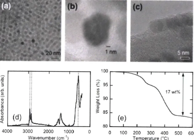
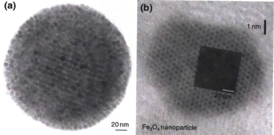
4000 3000 2000 1000 Wavenumber (cm ) 100 J 801 1 1 0 0 100 200 300 400 Temperature ("C)Figure 2-4: TEM images of magnetic nanoparticles and their characterization. (a) TEM images of magnetic nanoparticles (b) HR-TEM showing atomic planes of nanoparticles (c) HR-TEM showing stabilizers OA/OAm (d) FTIR measurement (e) TGA measurement.
Monodisperse 7 nm magnetic nanoparticles, stabilized in a non-polar organic solvent with a mixture of oleic acid and oleyl amine (OA/OAm) surface monolayer, were synthesized using the
2
method provided by Sun et al. The synthesis of monodisperse, single crystal structures is important as these structures act as the building block for nanoparticles. As shown in Figure 2-4 (a), the nanoparticles have narrow size distribution with a diameter of 7 nm. To increase the contrast between nanoparticles and stabilizer, we used lacey carbon grids or thin perforated carbon films instead of carbon film TEM grids. The resulting TEM images are shown in Figure 2-4 (c). Individual nanoparticles are in the form of hexagons with an OA/OAm shell of -0.5nm. According to the FTIR spectrum of the OA/OAm magnetic nanoparticles in Figure 2-4 (d), the magnetite (Fe304) has adsorption band at 586 cm-1 and OA/OAm has the bands at 2852 and 2927 cm-1. The OA/OAm bands originate from methylene groups present. TGA measurements indicate that the OA/OAm account for 17 wt% of the total nanoparticle mass.
2.3.2 Clusters of magnetic nanoparticles
Self-assembled structures of clusters made using 7 nm magnetic nanoparticles were controlling by adjusting the solvent evaporation temperature of hexane in the S/O/W emulsion shown in Figure 2-2. Depending on the evaporation temperature, the resulting secondary particles could be categorized as Nanoparticles Crystal (NPC), Nanoparticles Amorphous (NPA) and Nanoparticles Doughnut (NPD). NPC was prepared by removing hexane at room temperature for 3 days, while NPA and NPD are created at 60 "C for 12 hours and 80 *C for 8 hours, respectively. With slow evaporation of hexane from the S/0/W emulsion, we obtained a crystal like structure. The slow evaporation allowed nanoparticles to move to a close packed structure with a low energy configuration. At 40 *C, we observed a polycrystal structure as shown in Figure 2-5 (c). Interestingly, this configuration appears both for clusters and single magnetite particles. The superimposed figure at the top of the single magnetite image in Figure 2-6 (b) was obtained from Figure 2-6 (a). Additionally, the black small circles in Figure 2-6 (b) are a group of atomic plane, while Figure 2-6 (a) includes magnetic nanoparticles.
When the oil phase solvent was removed more rapidly at 60 *C, the particles could not organize in a well order structure, resulting in an amorphous structure. At 80 *C, which is higher than the boiling point of hexane, the magnetic nanoparticles immediately form clusters that encapsulate a hexane liquid core. Vaporized hexane escapes from the core to outside of the S/O/W emulsion, which results in the formation of doughnut-like structures. The sizes of the emulsion are about 1 jim and secondary particles formed after evaporation are stabilized by the negative charge (-60 to -90 mV) of the surfactant, SDS. The zeta potentials of each cluster type are listed in Table 2-1. Alkyl chains on the surface of magnetic nanoparticles participate in both nanoparticle-nanoparticle and nanoparticle-nanoparticle-surfactant interactions, which stabilize the self-assembled clusters.
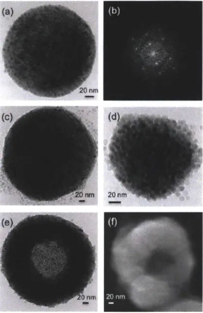
Figure 2-5: Magnetic nanoparticle clusters: (a) TEM image of a single-domain crystalline superlattice formed at low temperature (25 *C), (b) fast Fourier transform diffraction pattern for particles in (a) showing BCC (110) structure, (c) TEM image of a multidomain crystalline superlattice formed at intermediate temperatures (50 *C), (d) TEM image of amorphous cluster formed at higher temperatures (60 *C), and (e) TEM image and (f) SEM image of toroidal structures formed at 80 *C, above the solvent boiling point. The TEM image in (e) was paired with an image of the same cluster tilted at an angle of 300 for stereoscopic visualization to show that the toroidal aggregates have a true doughnut-like structure.
When the evaporation process is performed at room temperature for 3 days, the nanoparticles are arrayed with well-ordered structures resulting in NPC formation. We confirmed the structure of NPC using TEM as shown in Figure 2-5(a). We also confirmed the super lattice structure of the magnetic nanoparticles. The FFT (Fast Fourier Transform) image of the inside of the NPC is shown in Figure 2-5(b). The single crystal spot indicates (110) of the BCC (Body Centered Cubic). If the evaporation is performed at 60 *C for 8 hrs, magnetic nanoparticles in the emulsion can not be arrayed with a well-order structure, resulting in particles with an amorphous structure. The structure of NPA is confirmed in Figure 2-5(c). The FFT image in Figure 2-5(d), indicates a homogenous (disordered) structure of NPA. With a rapid hexane evaporation at 80 *C for 8hr, a doughnut like structure was observed. Considering that the boiling point of hexane is 69 *C, the rapid evaporation condition can be defined as when this. We hypothesize that doughnut structures are formed through a transitional structure with hollow cores surrounded by shells of nanoparticles that are ruptured when trapped hexane is released from the emulsion core. The NPD structure is confirmed in Figure 2-5(e) and (f). Figure 2-5(f) was taken by tilting the particle in Figure 2-5(e) at an angle of 300. We confirmed the doughnut structures of Figure
2-5(e) and (f) by Stereoscope (Type F-71, Forestry Suppliers Inc.).
(a)
20 nm
Figure 2-6: Nanoparticle lattice mirrors molecular ordering. (a) TEM image of nanoparticle clusters (b) HR-TEM image of magnetic nanoparticles. Inset image is from (a)