Publisher’s version / Version de l'éditeur:
Vous avez des questions? Nous pouvons vous aider. Pour communiquer directement avec un auteur, consultez la
première page de la revue dans laquelle son article a été publié afin de trouver ses coordonnées. Si vous n’arrivez pas à les repérer, communiquez avec nous à [email protected].
Questions? Contact the NRC Publications Archive team at
[email protected]. If you wish to email the authors directly, please see the first page of the publication for their contact information.
https://publications-cnrc.canada.ca/fra/droits
L’accès à ce site Web et l’utilisation de son contenu sont assujettis aux conditions présentées dans le site LISEZ CES CONDITIONS ATTENTIVEMENT AVANT D’UTILISER CE SITE WEB.
Internal Report (National Research Council of Canada. Division of Building Research), 1957-06-01
READ THESE TERMS AND CONDITIONS CAREFULLY BEFORE USING THIS WEBSITE.
https://nrc-publications.canada.ca/eng/copyright
NRC Publications Archive Record / Notice des Archives des publications du CNRC :
https://nrc-publications.canada.ca/eng/view/object/?id=766f2517-bf08-43c2-8913-673d2a19f75e https://publications-cnrc.canada.ca/fra/voir/objet/?id=766f2517-bf08-43c2-8913-673d2a19f75e
NRC Publications Archive
Archives des publications du CNRC
For the publisher’s version, please access the DOI link below./ Pour consulter la version de l’éditeur, utilisez le lien DOI ci-dessous.
https://doi.org/10.4224/20338230
Access and use of this website and the material on it are subject to the Terms and Conditions set forth at
Thermal radiation and its effect on the heating and cooling of buildings Stephenson, D. G.
NATIONAL RESEARCH COUNCIL OF CANADA DIVISION OF BUILDING RESEARCH
THERMAL RADIATION AND ITS EFFECT ON
THE HEATING AND COOLING OF
BUILDINGS
by
D.G.Stephenson
Report Noo 121
of the Division of Building Research
OTTAWA
PREFACE
The prediction of the energy exchange
「・エキセ・ョ the exterior surfaces of a bUilding or other
construction and the outdoor environment cannot readily be reduced to a simple basis. The dominant weather elements which affect this energy exchange are sunshine, air temperature and wind. In addition, the
shape and orientation of the building and its relationship to the ground and surrounding objects, as well as the
absorptivity and emissivity characteristics of the surfaces involved enter into the problem. Additional complication is provided by the effects of rain, 」ッョセ
densation and evaporation. Fortunately these latter effects are not always involved and so, as is done in this report, they are usually disregarded. Even
without them the problem is difficult enough.
The normal meteorological readings which are taken do not adequately describe the weather for purposes of calculating its effect upon the surface energy exohange, partiCUlarly when sunshine is involved. Even if all the individual factors are measured there remains the problem of recombining these multiple streams of variables in the calculation. There is, fortunately, a way of achieving some simplification; a combined
factor called sol-air temperature can be used so that it becomes necessary only to deal with a single stream of data.
This report discusses the sol-air tempera-ture concept and the ways in which values of sol-air temperature oan be obtained. A series of special measurements are proposed, and the instruments re-quired to make them are considered. Accurate records of sol-air temperature would be of great assistance in the calculation of the heat gains of buildings in
Bummer.
ottawa
ABSTRACT
The sol-air temperature concept is very useful when calculating the heat exchange at the outside surfaces of bUildings. To be accurate the sol-air temperature must take account of the exchange of long wave-length thermal radiation as well as the solar radiation. It must not be based on a surface heat transfer coefficient which assumes that convective and radiative heat transfer are always in the same direction and in the same proportions. The
expression for the sol-air temperature given by Parmelee and Aubele appears to be the most satisfactory:
t'sa
=
t a+ - - - =
セiウ - E • b. IL hc + hr where and LlIL=
'V Ta4(0.45 -PNSSセI
h r=
E •
VeTs4 - Ta4)/(Ts - Ta )The sol-air temperature defined in this way can be used to oalculate the heat exchange at the surface of a building by
q
=
(hc + hr)(t'sa - t s)The sol-air thermometer in the form described by Mackey and Wright will not, in general, indicate the correct sol-air temperature for a wall of different size even though the material and exposure are the same. Thus it is recom-mended that sol-air temperature should be calculated from data on the incident thermal radiation, the emissivity and absorptivity of the wall surface and the convection heat transfer coefficient at the surface. The apparatuses for measuring these data are discussed.
THERMAL RADIATION AND ITS EFFECT ON THE HEATING AND COOLING OF BUILDINGS
by
D. G. Stephenson
To estimate accurately the maximum heating and cooling load for any bUilding whose walls and roof have an appreciable heat storage capacity, it is necessary to account for the damping (and phase lag) in the daily fluc-tuations in heat flow caused by this capacity. At the outside surfaces of a building there is heat transfer by oonvection, the absorption of incident radiation of all wave-lengths, and the emission of long wave-length
radiation. For non-steady-state heat flow determinations it is a great simplification if all these heat transfer processes can be replaced by one equivalent process. This is equally true whether the determination is being done mathematically or by an analogue. The advantage of using a fictitious temperature and surface coefficient to replace the parallel convection and radiation processes has been recognized for many years. More than one method of deter-mining the fictitious temperature and thermal resistance of the surface film has been suggested. The following discussion examines these methods in relation to the
phenomena involved, as a basis for decisions as to the most acceptable way of describing the thermal influence of
weather upon bUildings. Nomenclature
A and B
E
h
constants defined by equation 22
e.m.f. developed by thermopile
combined convection and radiation surface co-efficient = h + h
c r
surface coefficient of heat transfer by oonvection radiation coefficient of heat transfer
=
E •
sr::
(Ts + Ta)(Ts2 + Ta2)angles of incidence of direct solar radiation on vertical and horizontal surfaces respectively
intensity of short wave radiation, direot and diffuse combined
k t **k q T r T
,t
a a taa t l aav
I € " I f セ) E
thermal conductance of heat meter thermal conductivity of air
characteristic length; over-all length of a surface in the direction of the air flow past the surface
partial pressure of water vapour in the
atmosphere at ground level. in. mercury heat flux into the surface
temperature of the ambient air film temperature
=
(T + T )/2a a
radiometer temperature surface temperature
sol-air temperature as defined by Mackey and Wright (equation 7)
sol-air temperature defined by Parmelee and Aubele (equation 12)
air velocity parallel to surface outside the boundary layer
emissivities of surface for short and long wave radiation respectively
emissivities of radiometer surfaces for short and long wave radiation respectively emissivities of surface of earth for short and
long wave radiation respectively Steffan's constant
density of air viscosity of air
*
T indicates absolute temperature and t temperature of.3
-Sol-Air Temperature
The idea of using a fictitious temperature which would combine the effects of heat transfer by radiation and convection was first proposed by Mackey and Wright (I). In their first paper it was called equivalent outdoor air
temperature (in subsequent papers - sol-air temperature) and was defined as: II - - - the temperature of the outdoor
air which, in contact with a shaded wall, would give the same rate of heat transfer and the same temperature distribution through the wall as .exist with the actual outdoor air tem-perature and incident solar radiation."
hC(ts-t
A )-.I..._...L...._ _MMMlN⦅セ⦅MMMMlNMMMMBGMMMMBM
t
s
The heat balance at the surface gives
q
=
h (t - t ) + '\. I + r: (I L - r"7"" T 4) I c a s セ s c v S ••••••••• butセis
+ E (I L - VTs 4 )=
Net Exchange •••••••••••• 2 By the definition of sol-air temperatureq = h(tsa - t s ) ••••••••••••••••••••••••••••••••• 3 where h is the combined convection and radiation coefficient for a shaded wall. If it is assumed that I L
=
セt。T
i.e., that the surroundings radiate as a black body at air temperature.
sr: (T 4 - T 4) = h (t - t
s ) ..•••••••••••.• 4
a s r a
where hr -- E. yr(Ta4 - Ts ) (Ta - Ts) •••••••••••••••4 /
5
•
セ 4 E V T
f 3 •••••••••••••••••••••••••••••• 5a
Then q
=
(he + hr) (t4
-If h
=
hc + hr equations 3 and 6 can be combinedto give
セiウ
t sa
=
ta + h ••••••••••••••••••••••••••••••••7
Equation 7 is the equation for sol-air temperature
given by Maokey and Wright. They pointed out (2) that
equation 3 indicates that t s will equal t sa if q
=
0, i.e. aperfeotly insulated surfaoe will be in thermal equilibrium with its surroundings when it is at the sol-air
tempera-ture. They use this observation as the basis for suggesting
that sol-air temperatures can be obtained direotly by measuring the temperature of thin slices of bUilding materials,
supported by materials of very low thermal conduotivity and
exposed to ambient wind and radiation oonditions. The sol-air
temperature obtained in this way will not give the correot value of q if used in equation 3 unless the value of h for the surfaoe in question is the same as that whioh existed
at the surface of the sol-air thermometer. This equality of
h is very unlikely since hc is dependent on the size of
the surfaoe; being higher for small surfaces.
In all the foregoing discussion it has been
assumed that I = VT 4. Parmelee and Aubele (3) oompared
L a
the data on I L whioh they obtained, with previous work
by セョ・ウ and Dines, and showed that the inoident long wave
radiation from a cloudless sky is related to dry bulb temperature and the partial pressure of water vapour by
IL
=
vrTa4(0.55 + 0.33セI
••••••••••••••••••• 8where P is partial pressure of water vapour at ground level
w
in inohes of meroury.
Parmelee and Aubele use equation 8 to derive an expression for sol-air temperature.
4
They let I L
=
V Ta -o:
I L ••••••••••••••••••••••••••••••• 9where
6
IL=
'V"Ta4(0.45 - 0.33JP;)
10If this expression for I L is substituted into equation 1 it gives
5
-Then equations 3 and 11 give
• • • • • • • • • • • • • • • • •It 12
t'sa = ta +
The difference between
7
isd..-Is - E • .6. 11
h
t'sa and t sa as given by equation
t'sa
=
tsa - . . . . • . . . . • • . . . • . . . • • .• 13This indicates that the error in sol-air temperature, which is caused by the assumption that the surroundings radiate as a black body at air temperature, isE • セ 1
1
/h .
Fora surface seeing only a clear sky, セiQ has the value indicated by equation 10, while for a completely overcast sky, セ 11 iszero.
If sol-air temperature is calculated from equation 12 it is practically independent of surface temperature.
hc and hr are each dependent on the film temperature but
have temperature derivatives of opposite sign (Appendix 1). The importance of f! I was shown by Parmelee and Aubele by the following example:1
of sol-air atmosphere
when
The 1951 ASHVE Guide gives as the temperature for a horizontal roof
t sa
=
109.loF.¥h
=
0.25. 24-hour average seeing a clear This assumed f! 1 1 = 0, but A 11=
V" Ta4(0.45 - 0.33 Jpw) 10 Taking Ta=
5400Ras a 24-hour average and P
w
=
0.50 in. mercury (Dew Point = 59°F.)6 11
=
147 x 0.22=
32 Btu/hr. ft2 if f=
0.90 and h=
4.0t' - t __ 0.90 x 32 = -7.2 OF.
sa sa 4.0
For an indoor air temperature maintained at 7SoF throughout the period, the heat gain using the value of t'sa will be
6
-Thus the sol-air temperature should be calculated by equation 12 rather than by equation 78 All the data needed for this calculation arc not known accurately, so in a later section apparatuses are described which could obtain these needed data. However, until more experimental data are available the following values should be used:
(1) Surface coefficient h
The ASHAE Guide (1956) recommends for design calculations h
=
6"0. This is based on test data obtained from 1 ft. square samples at a mean エ・ュー・イ。エセイ・ of 20oF8 with a wind velocity of 15 m.p.h.(2) Ll I
L
This quantity should be calculated by equation
10 tah.'i.ng account of outside tanperature and humidity.
(3) Is
The values of Is for use in equation 12 should be the sum of the direct and the diffuse solar radiation which falls on the surface. Data on
Is for a horizontal surface are available for most first class weather stations. Few data
exist for Is incident on a vertical surfaoe, but an estimate can be made on the basis of the horizontal surface data. The relative inten-sities of the direct and diffuse radiation on a horizorrtal surface have been measured by Patterson
(4)
at Toronto. He found that 12 per cent of I (horizontal) is due to diffuse radiation from s a clear sky; and for very hazy conditions it could be as much as 30 per cent.Thus for olear conditions, Direct Solar
=
0.88 Is (horizontal). If ih is the angle of incidence of the direct beam on the horizontal surface and i v the angle of incidenoe on a vertical surface, the direct solar on the vertical sur-faoe isDirect Solar (vertical)
=
Direct Solar (horizontal) (cos iV ) •• 14 (oos ih)It is sometimes assumed that the diffuse sky radiation oomes Uniformly from all parts of the sky so that any verti-cal surface will receive half as much as a horizontal surface. This is convenient for present purposes but for highest
acouracy the data in the 1952 Guide P. 267 should be used. Then, neglecting reflection from the ground, the short wave
7
-radiation on a vertical surface is 0.88 cos i
Is (vertical) = ( v + 0.06) Is (horizontal) ••••• 15
cos i h
This factor must be increased to allow for the radiation reflected from the ground surface in front of the vertical wall. This reflected radiation is (1 - セGI Is (horizontal) where セB is the absorptivity of the ground surface. The
ground reflected radiation is uniformly distributed to the upper hemisphere.
Therefore,
Is (vertical) =(0.88 cos iy + 0.06 + 1
MRセGI
Is (horizontal) •• 16 cos i hcos iv and cos i h are conveniently tabulated in the 1952 ASHVE Guide on pages 269 and 270.
(4) セ and 6
The reflecting powers for the surfaces of many bUilding materials have been measured by Beckett
(5) • The absorptivity セ is equal to one minus the reflecting power of the surface. In the absence of any other data it is suggested that Beckett's values for surfaces which are similar to those in question should be used.
The value of IE for most commonly used materials is listed in McAdams
(6)
and can be used with confidence.Radiation Measuring Instruments
The thermal radiation which falls on the surface of a bUilding can be divided into セOッ classes:
(1) Solar radiation with wave-length less than
Rセ microns.
(2 ) Long wave-length radiation with wave-length greater than Rセ microns.
The solar radiation has its maximum intensity at a wave-length of セ micron while the black body radiation from terrestial sources has its maximum at wave-lengths around 10 microns.
8
-Since many surfaces have quite different absorptivities for long and short wave-length radiation it is necessary to measure the intensities of the radiation in each class separately.
Pyrheliometers
The U.S. Weather Bureau measures solar radiation at many locations in the United States and after testing all the available instruments they have accepted the Eppley
thermoelectric pyrheliometer as the most suitable for their needs (7). The construction details and characteristics of this type of pyrheliometer are described in a paper by T.H. MacDonald (8) and are only briefly summarized here.
The receiving surfaces of the Eppley pyrheliometer are concentric flat metal rings exposed in a common plane. One ring is coated vdth magnesium oxide and the other with lamp black. Because of the difference in absorptivity of these coatings the rings attain different equilibrium tem-peratures when exposed to sunlight. The output of the instrument is the e.m.f. of a platinum-rhodium (90-10) and gold-palladium (60-40) thermopile with junctions on the two rings. The receiving surfaces are protected by a glass bulb. The glass used for this bulb has an almost constant transmission factor for solar radiation.
One peculiarity of the instrument is that the
e.m.f. per unit of radiation flux decreases as the temperature increases so that a calibration is necessary at several
temperatures in the range usually encountered. The Weather Bureau tests also indicated that the calibration depends on the angle which the receiving surfaces make with the hori-zontal.
When radiation has an angle of incidence at the
イ・」・Qセョァ surfaces of less than 60°, the instrument output is proportional to the normal intensity times the cosine of the angle of incidence. For incidence angles greater than
60° the output becomes less than the cosine response (at 80° the response is down to 80 per cent of cosine response).
Hand (7) gives useful advice on the proper care of the instruments and the Weather Bureau method of
stan-dardiZing their instruments against a Smithsonian pyrheliometer. Actinometer
When Eppley pyrheliometers are used to measure solar radiation continuously it is necessary to have a
standard available against which the Eppleys may be checked. The U.S. Weather Bureau uses a Smithsonion pyrheliometer as its standard. The Meteorological Branch of the Department
9
-of Transport has found that a good thermopile radiometer is a more convenient working standard and has sufficient sta-bility to require comparison with a primary standard only once a year. The Kipp company of Delft, Holland makes a radiometer which is suitable for use as a working standard. Net Exchange Radiometer
The heat meter type of radiometer developed by Gier and Dunkle (9) can be used to measure the net exchange of energy at a surface. The heat meter element is placed parallel to the surface so that one side of the heat meter is exposed to the same incident radiation as the surface while the other side is exposed to the radiation reflected by the surface and the radiation emitted by the surface.
Thus the difference in the radiant energy incident on the two sides of the heat meter is the amount of thermal energy
exchanged between the surface and its surroundings.
In the following sections the relationship is derived between this net exchange and the e.m.f. developed by the heat meter thermopile.
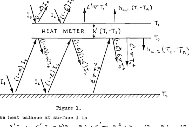
Figure 1 shows schematically the heat exchange at each surface of the heat meter.
T'l (T,-TA ) セ •
t
he,1
HEAT METER|
セ
セ-z:
\ ?---セ yt '" セ(J'I""
セ
V
&
r
s\(;
i」|セ
'0
-77777777777777777777777777777777777777777
T
s Figure 1. The heat balance at surface 1 isv'
Is + " T 4 )e-, €. IL = k (Tl - T
10
-and at surface 2
, , , 4 4 ,
c\...: HャMセiウ K・HャMセIilK・NvGBサゥZZNtウ -T
2 ) +k(TI- T2) =ho,2(T2- Ta) ••• 18
If these are subtracted it gives
セNセNiウKᄋeGHilMカtウTI]RォセtiMtRIKセiNvサtQT⦅tRTIKィ」LQHtiMt。I
If
tb'
= E ' t .e. both surfaces of the heat meter are assumed to be grey; and hc,1 = h 2 = h this simplifies to0, 0 + 4 •sr: T3 } •••••••••••• 21
セ
• (Net Exchange)=
(Tl - T2) { 2k + hc + 4 • E' • V- T3 } I { 2k + h or Net ..Exchange=
(T l - T )2 セi cwhere T is the average of T
l and T2•
The e.m.f. developed by the thermopile 1s
••• 20 E
=
(T1 - T2) (A + BT) ••••••••••••••••••••••••••• 22 ThereforeセRォG
+ hc + 4v:T3 } E セG Net Exchange = ••••••••••••••••••••23
A + BTThe quantity in braokets is the calibration constant which obviously depends on ォセ セL hc and T and is only valid when E' = セGL (i.e. when the surfaces of the heat meter are 'grey')
and when hc,l = hc,2.
If the surfaces are not grey the calibration
constant will depend on the relative intensities of the long and short wave-length radiation which is incident on the
meter. Similarly if hc,l does not equal hc,2 the oalibration oonstant will depend on Tl - T
a and T2 - Ta•
A radiometer of the Gier and Dunkle type is manu-faotured commercially by the Beclanan and \Vhitley Co. The heat meter surfaces are painted with Fullers Flat Black Decoret paint. This has セ = 0.94 approx, and E I = 0.86, so that the calibration of this instrument with sunlight will be somewhat in error for the combined long and short wave
provision 1s made to check the equality ofh 1
c,
and h 2 and to adjust the air streams to make c,
them equal if they are found to be different.
data. which wall.
11
-radiation which falls on the surface of the earth. Secondly, this instrument employs a small fan to circulate air over both surfaces of the heat meter element but there is nQ way to check easily that hc,l is equal to hc,2 nor to adjust the air flow to make the film coefficients equal if they are found to be different. It is important that the air velocity over the heat meter be high enough so that wind conditions will not change he appreciably. The Beckman and Vlhitley radiometer 1s influenced by winds at an angle to the direction of the air movement caused by the fan.
An 1mproyed radiometer of this same type has been described by Suomi, Franssila and Islitzer (10) which differs from the Beckman and Whitley apparatus in two important ways. These are:
(1)
(2) the absorptivity of the surface for long and short wave lengths is made more nearly constant than a surface covered by Fullers Flat Black Decoret, by covering parts of it with a lead-carbonate paint. This absorbs only 6 per cent of solar energy but has a high absorptivity in the infra-red.
This instrument has been proved capable of measuring the net radiation to within an accuracy of 2 per cent, except, for very small values of net radiation.
A net exchange radiometer can be used to measure total hemispherical radiation by simply placing it so that one side sees a surface of known temperature and emissivity.
Then the total hemispherical radiation is the sum of the net exchange and the radiation emitted and reflected by the
surface. This last quantity is easily calculated when the temperature and emissivity of the surface are known.
A Method of Measuring ィjLセil and Is
When calculating sol-air temperature by equation 12 it is necessary to know hc' AIL and Is along with other The apparatus outlined here would provide data from these three quantities could be determined for a test
l
An experimental determination of hc appears desir-able because of its importance when calculating sol-air
12
-determined from measurements made on actual walls. Additional experimental data for セil and Is applicable to vertical
surfaces are also needed since most previous work has been restricted to horizontal surfaces.
Figure 2 shows a laminated bakelite heat meter attached to the outside surface of a wall surrounded by a
large sheet of bakelite of the same thickness. The surface of the heat meter and its surround are painted the same colour so that the surface temperature will be uniform over the central portion. A net exchange radiometer measures the net radiant energy ・ク」ィセァ・、 at the surface.
If heat flow into wall is q
h
=
Net Exchange - q •• • ••••• ••••• •• • • • • • ••••• 24c t s - ta
The temperature at the middle of the heat meter is measured by a thermocouple. The surface temperature differs from this only by a small increment depending on q and the bakelite thermal conductivity so that an accurate surface temperature can be obtained.
These data will also give a value for the surface sol-air temperature
t'
=
t +q/h •••••••••••••••••••••••••••••••••••• 25
sa s
where h
=
h c + hrIf a pYrheliometer is mounted with its receiving surfaces parallel to the surface, the quantity セ IL can also be determined from its output and the other data.
Since
t t = t + Hセi 0\ - e:'C' • セI\. IL)I·UA... • • • • • • • • • • • • • • • • • 12
sa a s
then - t ) + d.:I - q ••••••••••••••••••• 26
s s
Thus with this apparatus it is possible to obtain hc' A IL and
I . Ifセ。ョ、・ are known for a wall surface it is then possible
tS calculate the sol-air temperature for the surface when
exposed to the same conditions as the test wall. This ability to obtain sol-air temperature for any wall from one set of measured data is an improvement on the sol-air thermometer which gives sol-air temperature for only one surface.
13
-py
RH E.L10ME..TE..f1BAKE-LITE.-5HE..E..T.
H E.AT ME.-T E..R
, 7777777777777777777V7777777777777777777777777777
't
NE.T eNセchangeLNLf
radiomeNteNNセァセadiation
hc(Ls-t,,)
Figure 2An Apparatus to Measure the Solar Absorptivity of a
Wall SUrface \VALL 5HAr:::'E,.... INSIDE..t blacセ \ \ \ \ \ \ \ \ \ \ \ 7 Figure 3
Two pyrheliometers mounted back-to-baok on a stand which can be rotated should be able to measure the
reflecti-vity of a surface for solar radiation. One pyrheliometer
measures the intensity of the radiation incident on the wall
while the other measures the refleoted solar radiation. The
ratio of the reflected to the inoident is the surface refleo-tivity, or one minus the absorptivity.
14
-By rotating the unit so that the pyrheliometers are interchanged, the unit will give a second value of
absorptivity. Tfle mean of these セヲャo values will be independent
of the pyrheliometer constants. The short shading tube defines the angle of view of the pyrheliometers. This is necessary since it is assumed that only reflected radiation is incident on one pyrheliometer, and without the shade it would see some sky as well as the wall.
L1Q..UID JACKE..T
INSULATION /
TH
E'RMO-COUpLE..
Ira jacketed thermopile
radiometer is placed against a wall surface and the
radiometer temperature is slowly raised from a value below the wall surface temperature to some value above it, the thermopile output vs. radiometer
temperature will be as shown in Fig.
5.
An Apnaratus to Measure the Low Temperature Emissivity of a Wall Surface Figure 4 セaoiome .Nteaセ TE..MP•
+
...
:J 0.. .... :J o u1 OI---::::IIot"'---.J CL o :ic:r
u1 :rr
Figure 5The temperature at which the output is zero is the wall surface temperature; and for radiometer temperatures other than the wall temperature, the output is
15
-4
4
Output = F (Tr) • セ • (Ts - Tr ) ••••••••••••••••••••• 27 thereroretilllTr (Output) ] T r=
T s=
peTs) x E •••••••••••• 28 Thus if the radiometer is sighted on a surfacewhere € is knovm (e.g. a black small angle cone € = 0.99)
one series of experiments will suffice to determine セHtウIN
Then, if the radiometer is sighted on a surface of unknown E,
€ can be found from equation 28 since both Ts and
are measurable.
This apparatus differs from the usual long wave-length emissivity apparatus in that it measures the surface temperature as well as the emissivity. Thus it can be used on walls without altering them in any way.
Conclusions
(1) The use of sol-air temperature is a very convenient way of accounting for heat exchange by radiation and con-vection when calculating the non-steady-state heat trans-fer to and through a building wall.
(2) A small sol-air thermometer will not indicate the correct sol-air temperature for a large wall even though they have the same surface and exposure.
(3) It is more practical to obtain the data needed to cal-culate air temperature than to try to measure sol-air temperature for many different wall surfaces. The data needed are: outside air temperature; the intensity of solar and long wave-length radiation incident on a surface of any orientation; the absorptivity of the
surface for solar and long wave-length radiation; and the convection heat transfer coefficient appropriate for the surface.
(4) A calculated sol-air temperature must take account of the long wave-length radiation which is exchanged at the
outside surface of a bUilding. This cannot be done by assuming that the surroundings radiate as a black body at outside air temperature.
(5)
All of the needed data are not now known with sufficient accuracy to permit the calculation of reliable sol-air temperatures.16
-(6) A continuous record of the sol-air temperature for the surface of the earth would be very useful. A degree-day correlation of frost penetration based on sol-air temperature degree-days should be more reliable than a
similar correlation based on outside air temperature alone. Similarily sol-air temperature data would be useful when studying permafrost regions and the effect of changing the surface emissivity.
General Remarks
Each surface of a bUilding has a different sol-air temperature vs. time relation; and since it is unlikely
that all surfaces will experience the seasonal extreme value during one 24-hour ー・イゥッセL one cannot say exactly, when the maximum heating or cooling load will occur. It is only by making a heating- or cooling-load calculation for a whole building, セ。ォゥョァ account of infiltration, solar gain through glass, and the latent cooling load if any, for each time when a maximum might occur, that the actual maximum for a season can be found.
If an outside air temperature is chosen, which is exceeded only
5
per cent of the time during the average cooling season and if complete data are available for every day onwhich this particular temperature is exceeded, a complete cooling-load calculation can be made for any building for each of these days. If a cooling load is chosen so that half the previously calculated loads are above it and half below, one can then say that this load will be exceeded only Rセ
per cent of the time during an average cooling season. The reliability of this approcah is improved as the number of calculations and cooling seasons is increased •.
This method of arriving at the heating or cooling load for a bUilding is only practical if the data are on punched cards so that the calculations can be made on a computing machine.
The data needed for the periods when maximum heating and cooling requirements can be expected are the hourly average values of: the sol-air temperature for each outside surface of a building, wind speed and direction, outside air tempera-ture, dew point temperatempera-ture, and solar radiation incident on the window surfaces.
Recommendations
1. It is suggested that the Division expand the program for meteorological observations to include the data necessary to
calculate h c' Is, and セil for the exterior surfaces of buildings. The objects of this study would be twofold:
17
-(a) To determine if all the needed data can be inferred with sufficient accuracy from the observations which are now being made by the Meteorological Branch. (b) If additional observations are found to be necessary
the DBR station could be the prototype for the new instrumentation which might be set up at some
meteorological stations.
2. In view of the large number of data which will be obtained from even one station and the amount of computation necessary to reduce these data to the required form, it is reoommended that methods of automatio data recording and processing be investigated.
Referenoes
(1) Maokey, C.O. and L.T. Wright Jr., Summer oomfort factors as influenced by the thermal properties of building-materials. セt。ョウN aセイャveL Vol. 49, 1943, p. 148. (2) Maokey, C.O. and L. T. Wright Jr., The sol-air
thermo-meter - a new instrument. Trans. ASHVE, Vol. 52, 1946, p. 271.
(3) Parmelee, G.V. and W. W. Aubele, of atmosphere and ground. 1952, p. 85.
Radiant energy emission Trans. ASHVE, Vol. 58,
o "
Patterson, J, Comparison of the Angstrom pyrheliometer and the Callendar sunshine recorder and the deter-mination of the proportion of heat received on a horizontal surface from the diffuse radiation from the sky to that received from the sun.
Meteorological Service of Canada, M.S. 50, 1912. Beokett, H.E., The reflecting powers of rough surfaces
at solar wave-lengths. Proc. Phys. Soc., Vol. 43, Part
3,
No. 238, liay 1931.McAdams,
W.H.,
Heat transmission. McGraw-Hill, 1954.(4)
(5)
(6)
(7) Hand, I.F.,
ments. Pyrheliometers and pyrheliometric measure-U.S. Dept. of Commerce, Weather Bureau, 1946.
(8)
(9)
(10)
MaoDonald, T.H., Some characteristics of the Eppley pyrheliometer. Monthly Weather Review, Vol. 79,
August 1951, p. 153.
Gier, J.T. and R. V. Dunkle, Total hemispherical radio-meters. A.I.E.E., Proceedings, Vol. 70, 1951, p.l. Suomi, V.E., Matti Franssila and Norman F. Islitzer,
An improved net-radiation instrument. Journal of Meteorology, Vol. 11, No.4, Aug. 1954, p. 276.
AEpendix I
Variation in Outside Surface Coefficient with Film Temperature The outside film coefficient h is given by
Therefore
For forced convection where the air flow over the surface is turbulent the convection coefficient h c is given by Thus hc •
.Q.
=
0.03 (v •I'
.
.1.)0.80 k /.A-d he + dJL _
d k = 0.80 {d V + dP
+ dL
-
セ
J
heL
k VI'
Q セ When Tf is the only variable and has a value of about 500
0R d k
=
d
kl?>Tf k k d,o-=
Ot{
C>Tf ,Pr>
セ]
d?/dTf
/"
.r:
• d Tf セ + 0.0018 d T f • d Tf= -
0.0020 d Tf • d Tf = + 0.0016 d T f Therefore、ィ」Oセtヲ
= 0.0018 + 0.8 (- 0.0020 - 0.0016) he = -hr =i: 4 • t •v.
Tf 3 sod
ィjセ
Tf:i:
+ 12 • €. • "T. Tf 2A - 2