Publisher’s version / Version de l'éditeur:
Vous avez des questions? Nous pouvons vous aider. Pour communiquer directement avec un auteur, consultez la première page de la revue dans laquelle son article a été publié afin de trouver ses coordonnées. Si vous n’arrivez pas à les repérer, communiquez avec nous à [email protected].
Questions? Contact the NRC Publications Archive team at
[email protected]. If you wish to email the authors directly, please see the first page of the publication for their contact information.
https://publications-cnrc.canada.ca/fra/droits
L’accès à ce site Web et l’utilisation de son contenu sont assujettis aux conditions présentées dans le site LISEZ CES CONDITIONS ATTENTIVEMENT AVANT D’UTILISER CE SITE WEB.
Research Paper (National Research Council of Canada. Division of Building
Research), 1957-10
READ THESE TERMS AND CONDITIONS CAREFULLY BEFORE USING THIS WEBSITE.
https://nrc-publications.canada.ca/eng/copyright
NRC Publications Archive Record / Notice des Archives des publications du CNRC :
https://nrc-publications.canada.ca/eng/view/object/?id=96cffcfc-66e1-4c70-819d-c82e2d694d3b
https://publications-cnrc.canada.ca/fra/voir/objet/?id=96cffcfc-66e1-4c70-819d-c82e2d694d3b
NRC Publications Archive
Archives des publications du CNRC
For the publisher’s version, please access the DOI link below./ Pour consulter la version de l’éditeur, utilisez le lien DOI ci-dessous.
https://doi.org/10.4224/20375152
Access and use of this website and the material on it are subject to the Terms and Conditions set forth at
Structural test of a house under simulated wind and snow loads
Authorized Reprint from the Copyrighted Symposium on Full-Scnle Tests on House Structures
Sgecial Teclmical Publicaliotr No. 210
Published by the
AKERIC,\N SOCIETY FOR TESTING M,\TERULS
STRUCTURAL TEST O F A HOUSE UNDER SIMULATED WIND AND SNOW LOADS
House structures, in contrast to in- dustrial buildings and other larger struc- tures, do not generally lend themselves to the normal methods of structural design. For this reason the design of wood frame houses in Canada, as well as in other countries with similar climatic condi- tions, has developed largely through experience or tradition.
I t is often thought that conventional house construction is overdesigned and that substantial economies could be achieved if a means could be found of evaluating the structural strength and rigidity of a completed house. This need ' for evaluating the structural sufficiency
of a house design has become more pro- nounced with the introduction of new materials and new methods of combining
Shortly after the formation of the Division of Building Research (DBR) of the National Research Council of Can- ada, in Ottawa in 1947, it was decided to begin a research project on structural testing of full-scale houses. This paper describes the first such test, conducted by the Division in the summer of 1954.
Work on this project was begun with a literature survey of pertinent work by other research organizations. It was found that work in this field had mainly been done in the United States by the Naval Civil Engineering Research and Evaluation Laboratory at Port Hue- neme, Calif.; in Great Britain by the British Building Research Station; and in South Africa by the National Building Research Institute.
both old and new materials in house
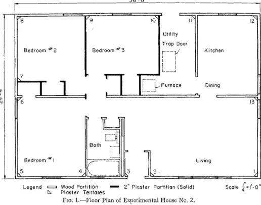
construction. I n some cases, a new con- D B R EXPERIMENTAL HOUSE struction can be compared structurally The the structuraI with conventional construction with test was one that had been built in 1948 some success, but in other cases there is for experimental Purposes but not par- no direct basis of comparison^ E~~~ when ticularly for a structural test. The floor
a comparison is possible, there remains plan and cross-section of this house are the question of overdesign as it is fie- shownin Figs. 1 and 2, respectively. The quently not known if conventional con- was a basementless, One-storY, struction is overdesigned. The structural 36 f t long assessment of house designs must, there- and 24 f t wide. It had three bedrooms, a
fore, be based in part upon information living room, a kitchen, a bathroom, and obtained from full-scale house tests in a
which simulated live loads are to The foundation walls mere of concrete a house. blocks and extended to a depth of 3 or 4 ft below grade to bedrock. Sill plates,
Building Design Section, National Research 2
by 6 in., were fastened to the top of the
Council of Canada, Division of Building Research.
Ottava, Ont. foundation wall with anchor bolts.
29
Legend: o Wood partition
-
2" Plaster Partition (Solid)h Plaster Telltales
FIG. 1.-Floor Plan of Experimental House No. 2.
S c a l e :
5.
I'-o"
V - Cr imp Aluminum Raafing
Insulation and
3in. Rock Wool ' 11'1111 1 2 b v 4
pope.
41;;;
1
L
In. Gypsum
) I 2 # S a t u r a l e d Felt
FIG. 3.-Typical Wall Section.
The floor consisted of cliagoilal sub- flooring,
+;
in. thick, covered generally by l~arclwoocl flooring2
in. thick.The exterior tvalls were collstructed of
2 by &in. wood stuclcling placecl on 16-in. centers, and bracecl by 1 by 4-in. cliagoilal members let into the stucls a t each corner of the house. Horizorltal 2 by 4-in. girths were placecl between the studs at the miclheight of the studs. T h e studdiilg was covered 011 the outside with 12-lb
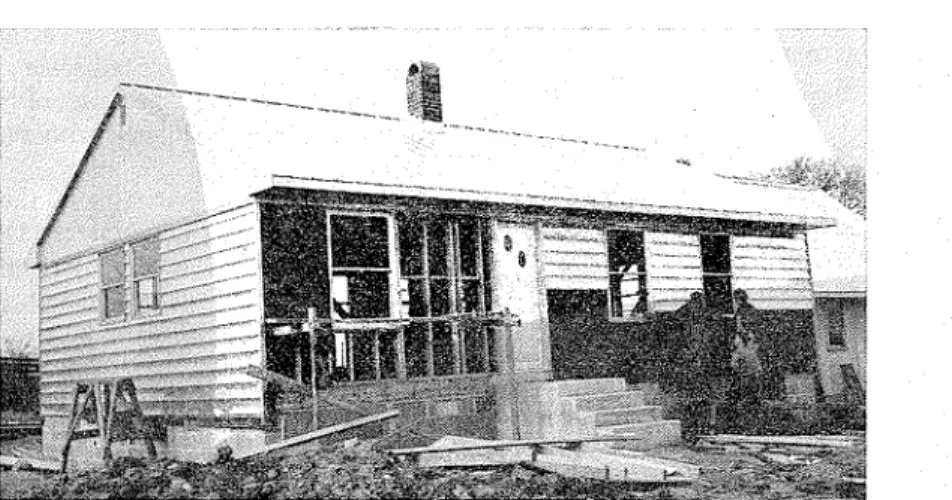
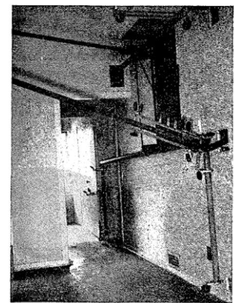
asphalt-satura ted felt paper, over which interlocking aluminum siding, 6; in. i11 width, was nailed to the studs (Fig. 3). Figure 4 shows part of the uilclad fram- ing and the alumirlum siding being applied to the wall studs over the satu- rited felt.
An important and unusual feature of
FIG. 4.-View of Exterior Wall during Construction Sho\ving Framing Details and Aluminum Siding bcing r\pplictl.
Floor joists, 2 by 8 in., 16 in. on centers, spanned each half width of the house and were supported a t the center of the house by a wooden beam made up of 2 by 10- in. planks, running lengthwise through the center of the house. This beam was supported in turn by the end walls of the concrete block fourldatiorl and by piers a t approximately the third points of its span.
the construction of the exterior walls was the oinission of exterior sheathing. Ex- terior sheathing normally contributes to the strength and stiffness of conveiltional exterior wall construction; it was not included in this structure so that a study could be made of the effect of such a n omission.
The roof framing consisted of 2 b y 4-in. rafters placed on 16-in. centers on
a 6 in 12 slope with 1 by 4-in. collar ties layers of gypsum plaster to give a better for each pair of rafters. The collar ties indication of harmful deformations a t the were fastened to each other a t midspan junction of the intersecting planes. by a 1 by 4 i n . longitudinal member
nailed to their underside. PURPOSE AND SCOPE OF
The aluminum roofing was supported STRUCTURAL TESTS
by 1 by 6-in. roofing boards which were nailed to the top of the rafters. These boards were spaced approximately 6 in. apart and were covered by 12-lb asphalt- saturated felt. V-crimp aluminum roof- ing, 30 in. wide, and running the full length of the rafters, was applied parallel to the rafters, over the asphalt-saturated felt. The aluminum sheets overlapped
7
in. along their sides and were double V-crimped a t the joints.
The ceiling construction consisted of 2 by 6-in. joists with a 12-ft span, sup- ported near the center of the house by a partition wall. The construction was done according to normal construction prac- tice and does not represent above aver- age workmanship. For example, the lower ends of the rafters were not all nailed directly to the joists at the wall plates, and thus, at some points, the ceiling joists were merely toe-nailed to the top wall plate. The interior finish of the ceiling was gypsum wallboard $-in. thick.
The central load-bearing partition and most of the other partitions were con- structed of 2 by 4-in. studs placed on 16-in. centers. Three partition walls and some closet walls (Fig. I), however, represented another experimental feature of the house consisting of 2-in. solid plaster walls. Figure 1 also shows the plaster telltales which were installed in a number of interior corners a t ceiling level to observe damage resulting from load- ing. The plaster telltales were made by removing the interior paint from the gypsum wallboard over an area of sev- eral square inches on each of the three intersecting planes in each corner and by replacing the paint with returned
Structural tests that may be conducted on the various elements, components (partial assemblies), and complete assem- blies of domestic dwellings are all inter- related. Structural tests on elements such as joists, rafters, studs, or on components such as floors, walls, or roofs, can reveal the strength and stiffness of the speci- mens but may not always give a proper indication of the strength and rigidity of the complete dwelling, assembled from these components or elements. Full-scale dwellings must be tested, therefore, if a useful attempt is to be made in correlat- ing the results of such investigations. The testing of reduced-scale models would be difficult because of various scale effects, particularly with regard to nailing.
The two main purposes of the struc- tural test on this house were (1) to ob- tain information on the strength and stiffness of a full-scale single-story house without exterior sheathing, and (2) to obtain experience in full-scale testing and in evaluating the strength of house frames.
A further reason for the test was the hope of obtaining information which would be useful in writing performance requirements for houses in Canada which could be used in connection with the acceptance of new types of construc- tion.
The performance was to be evaluated on the basis of deformation and strength. Deformations of the load-supporting members under design live load may, and often do, cause unsightly cracks in walls and ceilings. The possibility of such damage seemed particularly real in the house tested, as it had no exterior sheath-
ing. To check this it was decided to apply first the design loadings of the National Building Code of Canada (1953) for wind and snow and to observe deformations and possible damage under these loads. The strength of the house was to be tested by loading beyond the design live loads to the point of failure. Since, how- ever, it was not the intention to damage the test house beyond the state of pos- sible repair, it was decided to carry the
The second method makes use of a reac- tion framework over the test house, in- ward and outward thrusts being applied by double-acting hydraulic rams.
The first method has the advantage of simplicity of assembly but is not readily adaptable for applying outward thrusts to moderately sloping roof surfaces and has some other disadvantages.
The second method is more compli- cated to design and assemble but may be
Hydraulic Ram ond Tensior~ and Compression Strut
Hydroul~c Ram and Tension and Compression Strut Legend.
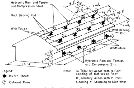
lnword Thrust Outward Thrust
Note: 16 Tributor Areos With 4 Point Looding a/ Rof ters on Roof 8 Tributary Areos With 2 Point Loading of Studding on Side Wotls FIG. 5.-Points of Loading.
loading only to a point of relatively minor damage.
Clzoice of a Loadilzg System:
One of the first problems in the plan- ning for this test was the selection of a loading method. A review of methods used by other research organizations re- vealed the two most promising methods. The first uses steel cables anchored to the ground at one end and directed over columns through a loading mechanism and a load-measuring device to load- distributing pads on the roof or side wall.
justified if the facilities are available. With a rigid reaction framework span- ning the test house, simultaneous in- ward or outward thrusts may be applied and controlled from a central position without altering the test house very much.
After careful consideration, and since the Division had an available stock of Bailey bridging components which could easily be adapted to use, it was decided that the reaction framework combined with hydraulic tension jacks to apply the loads should be used.
Another question that arose during the planning of this test was the choice of the
degree of load distribution to be achieved on the walls and roof. Maximum shears or bending moments could be duplicated in the members by concentrated loads, or a system of loading could be used that would approach uniform loading of the structure a s a whole and produce the over-all effect of the uniform loadings assumed in the design. The latter system
volved in providing a loading system: that could be used t o apply loads either vertically or a t right angles to the roof would have been considerable, it was de- cided t o provide a system that would apply loads a t right angles to the roof only and disregard the component of the snow loading parallel with the slope of the roof.
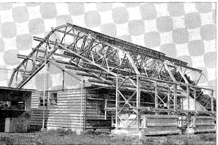
FIG. 6.-General View of T e s t Assembly. of loading was decided upon. The roof
and side wall loading distribution is shown in Fig. 5 .
Pigure 5 also shows that the loadiilg system was designed for the various loads to be applied a t right angles to the roof and side walls. This system represents the ilormal wind loading condition but does not represent the correct system for snow loading which should be vertical (loads in pounds per square foot of horizontally projected area). Since, how- ever, the test house did not have exterior sheathing to contribute strength against racking loads, it was originally thought that the wind loads would have the greatest influence on the interior finishes. As the additional work and expense in-
Reaction Framework afzd Loadi~zg M e w - bers:
T h e reaction framework spanning over the top of the test house was composed mainly of Bailey bridging, with addi- tional specially designed components. This framework was supported by specia, foundation pads and weighted down by large boses filled with crushed stone. T h e erection of the steel work was done by an outside firm wit11 the help of a mobile crane.
Each roof slope was divided into 16 equal tributary areas of loading and each side wall into 8 areas, a s indicated in Fig.
5. Hardwood loading pads were installed on the side walls and the roof and bolted to the 4-in. I-beams. Sponge rubber
DOREY AND SCHRIEVER ON SIMUL.~TED WIND .4ND SNOW LOADS 35
in. thick was used between the surface of the roof and the hardwood to provide a compressible medium between the two surfaces. On the roof the pads were bonded by glue to the aluminum sheet- ing so that both an upward and down- ward force might be applied. Later during the test a partial breakdown in the glue bond occurred, making it neces- sary to fasten the pads by wires to the
tension and compression struts. Figure G shows a general view of the test assembly.
Dejlection Measurilzg Apparatus:
A system of pulleys and wires was used inside the test house to measure the de- formations under load. This is a con- venient system to measure in a central location deformatioils a t widely sepa- rated points of a structure. I t can be
Front W = W i d t h o f House
m
u
Planes A 8 D Elevationg:
Plones B 8 C L e g e n d : C+ H o r i z o n t o l D e f l e c t i o n Wireg+
H o r i z o n t a l and V e r t i c a l D e f l e c t i o n W i r e N o t e :Arrows Point Away F r o m Reference Point i n Direction o f D e f l e c t i o n W i r e FIG. '/.-Planes of Deformation.
rafters through the roofing. The side wall loading pads were fastened to each stud with steel wire through the wall.
Pairs of loading pads were then con- nected a t their midpoint to a cross- whiffletree which in turn was connected by a pin joint a t its center point to a tension and compression strut. Each of the 24 tension and compression struts were restricted to unidirectional move- ment a t right angles to the plane being loaded. Hydraulic rams were later mounted between the channels of the
used when the deformations are espected to be large enough to be read without magnification.
Piano wire, 0.010 in. in diameter, running over a system of 2%-in. lo~v-fric- tion aircraft pulleys, was installed to register horizontal and vertical move- ments 011 four deformation planes, one
a t each of the third points in the interior and one a t each end wall on the exterior as show11 in Fig. 7. The pulleys, over which the ~vires are running, must not be affected by the movements of the house
during the test. I n this case the chimney, which is near the center of the house, was used to support the deflection ap- paratus inside the house and all connec- tions between the chimney and the house were removed.
Two additional wires were installed on one of the end-wall planes to indicate vertical and endwise movement a t the ridge-board level of the test house, and one wire to indicate whether the deflec-
FIG. 8.-Interior Deflection Apparatus.
tion apparatus had been disturbed. This made a total of 43 wires.
All the wires leading from the various points in the house were brought through one window opening in the end wall to a deflection board in the instrument hut. Figure 8 shows the deflection apparatus in the living room and hallway and the way in -which the system was at- tached to the chimney through the larger opening madein the partition wall. Fig- ure 9 shows the termination of the 43 wires on the deflection board, each wire being tensioned by a 1-lb weight, the lower edge of which was used in marking
successive deflection readings on the board. The instrument hut also housed the hydraulic console unit and the power supply transformers.
Loading Equipp~zetzt:
The hydraulic equipment for this test included 24 tension jacks, a n air accumu- lator, a console unit, and special lines and fittings.
All hydraulic rams were calibrated for hydraulic pressures ranging from 0 to
FIG. 9.-General View of Instrument House.
2000 psi before the test. The connections to the hydraulic rams on the struts and Bailey transoms were so designed that the direction of the force exerted by the hydraulic rams could be reversed, thus making it possible to apply either a push or a pull to the area of loading.
The rams were operated from the con- sole with four pressure channels, each of which could be operated at a different hydraulic pressure, one for each of the four surfaces of the test house. Four rams of equal thrust capacity were installed on each of the side walls, and eight of equal thrust capacity on each of
I Plane A - A I I Plane 6 - 0 I o.o& I I I I I J P l a n e C - C Plane D - D
(a) Wind Velocity 90 mph.
I I I P l a n e A - A I 0.0- 2 0 6 " Plane 6 - 0 (b) Wind Velocity 120 mph. Undistorted Frame --- Distorted Frame
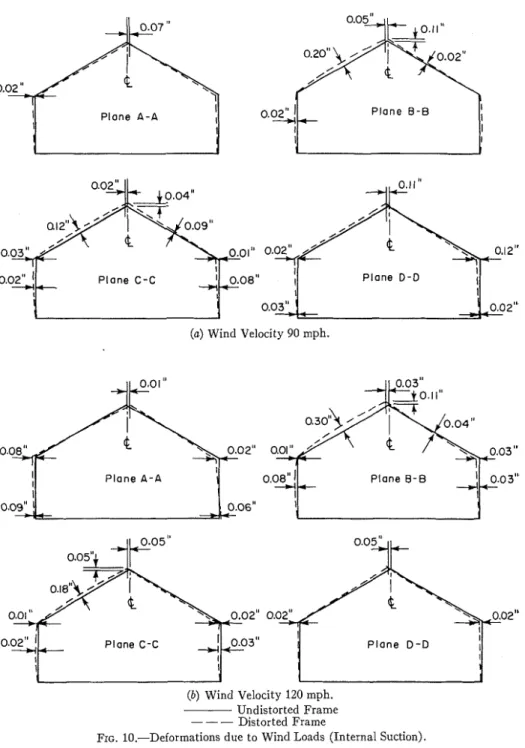
FIG. 10.-Deformations due to Wind Loads (Internal Suction).
NOTES.-Refer to Figs. 5 and 7 for loading and deflection points. Deformations are not drawn to scale.
the t ~ o roof slopes. Each of the four pressure channels had its own pressure gage and operating valves in the console. T o facilitate accurate loading an air accumulator, which could be charged with a booster pump to pressures in accord with the recluirements of the hy- draulic rams, was connected to the con- sole unit.
The sequence of loading phases for this test was from the least to the most severe conditions as follolvs:
(a) ii'ind loads: internal suction, (b) \\'incl loads: internal pressure, (c) One-half design snoiv load plus wind loads, and
(d) Snon7 loads.
According to the 1953 edition of the National Building Code of Canada, 90 mph is the design wind velocity for the Ottawa area and 120 mph is the highest mind velocity that might reasonably be expected in the populated areas of Canada. I t was decided, therefore, that the \vincl loads ~vould first be carried to the design velocity of 90 rnph and main- tained for 1 hr, then released and re- applied up to a velocity of 120 mph for both an internal suction and an internal pressure condition.
There was some doubt as to what per- centage of the design snow loading should be used for the combined loading condi- tion \vhich is not stipulated in the Na- tional Building Code. I t was decided that the maximum amount of silow which might be espected to remain on the roof under high wind velocities would be not more than
4
the design snow loading.T h e magnitude of the design snow loading was arrived a t by direct compu- tation from the information given in the National Building Code (1953). The silolv loads applied during the test were
the components of the vertical loads acting a t right angles t o the plane of the roof.
I;I/i?zd Loads-I~ttenzal Suction:
Internal suction (windows open on leeward side only) was the first wind loading condition applied. This condition is less severe than t h a t producing internal pressure, as it results in smaller loads except on the windward wall. The loads were applied in increments of pressure corresponding to increases in velocity of 10-mph, beginiling a t 70 mph and ending a t the design velocity of 90 mph. T h e loads were maintained for
4
hr, and the loads for a velocity of 90 mph were main- tair~ed for 1 hr. Deformations were re- corded on the deflection chart in the instrument hut before and after each increment of loading and after complete unloading. A visual inspection was made of each of the 13 plaster telltales before and after each loading incremei~t to see if any cracks had developed. KO craclrs appeared during this loading phase. De- formations resulting from the first phase of loading are shown in Fig. 10 (a).T h e next loading phase was a continua- tion of the loading scheclule given above up to loads corresponding to a wind velocity of 120 rnph. Each wind load was sustained for 1 hr after a 90-mph wind velocity loading was reached.
After reapplying pressures ecluivalent to a 90 rnph wind velocity a crack in tell- tale No. 5 was discovered, and toward the end of the l-hr period of sustained loading, a second craclr became visible in telltale No. 9. All loads were then in- creased to pressures corresponding to 100, 110, and finally 120 mph and main- tained for 1 hr in each case. During the 120-mph loading, cracks appeared in two inore telltales, Nos. 6 and 10. T h e deformations resulting from this phase of loading are sholvn in Fig. 10 (b).
DOREY AND SCIIRIEVER ON SINUL.~TED WIND AXD SXOW LO.-IDS 39
Plane D - D I
I I
.03" + 1 0.03"
-+I (a) Wind Velocity 90 mph.
(b) Wind Velocity 120 mph. Undistorted Frame --- Distortetl Frame
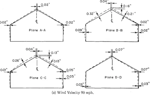
FIG. 11.-Deformations due to Wind Loads (Internal Pressure).
I\r'o~~s.-ltcfer to Figs. 5 and 7 for loading and dcflcction points. Deforlllations arc not drawr. to scale.
\irincl Dkcction: Fro111 the right.
I I I 0. 0 3 0.20" i P l a n e C - C 1 Plane D - D I I I 0.02" 1 1 0.01" P l a n e A - A 0.25 -+i &02"
&
I'-
Plane 0 - B 1 y- 0.01"0.0% I I P l a n e A - A 0.02" ---I* P l o n e B - B
-
ToI~~
I ~ 0 1 ' ' Plane C - C P l a n e 0 - D I*--
0.01 1. I I(a) Wind Velocity 90 mph.
0.04"
-7
I Plane A - A P l a n e B - B I I 0. o& 0.02" 0.0211, I I I P l a n e C - c-
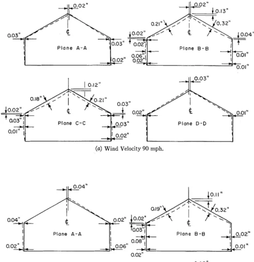
0.06" P l a n e 0 - 0 I I I I (b) Wind Velocity 120 mph. Undistorted Frame --- Distorted FrameFIG. 12.-Deformations due to
6
Design Snow Load plus Wind Loads.NOTES.-Refer to Figs. 5 and 7 for loading and deflection points Deformations are not drawn to scale.
At the end of 120 rnph sustained load- ing, all pressures on the console were re- leased in increments of one-third of the maximum pressures.
W i n d Loads-Internal Pressz~re:
The next wind loading condition ap- plied was that producing internal pres- sure (windows open on windward side only).
Loadings were again applied in incre- ments of pressure corresponding to in- creases in velocity of 10 rnph starting a t a velocity of 70 rnph and ending a t the design wind velocity of 90 mph. At loads corresponding to a velocity of 80 mph, a new crack became visible in telltale No. 6. The 90-mph load was maintained for 1 hr, but no further cracks appeared in the plaster telltales. Then pressures were re- leased in three steps to zero. The defor- mations resulting from this loading phase are shown in Fig. 11 ( a ) .
The next phase was a continuation of this loading up to a wind velocity of 120 mph.
During the process of increasing and maintaining loads to 90, 100, and 110 mph, no further cracks appeared, but during the 1-hr period of sustained load- ing for a wind velocity of 120 mph, a crack which appeared in telltale No. 5 earlier in the test extended noticeably. At the end of the loading period, all loads were released to zero. The deforma- tions resulting from this phase of loading are shown in Fig. 11 (b).
Up to this point in the test, the roof loads were in the form of an outward thrust at each of the loading points. Having completed the wind loading schedule, the next phase of loading in the direction of increasing severity of load- ing was that of a combination of wind and snow loading. Since the net result of such a combination of loading required a downward load on the roof, the 16
hydraulic rams acting on the roof sur- faces were reversed. During this inter- lude, the plaster telltales were rephoto- graphed to record the extent of cracking which had taken place under the applied wind loads.
One-half Design Snow Load plz~s W i n d Loads:
The combined loading of
+
design snow plus wind load was applied for wind velocities varying from 70 to 120 mph. At 70 rnph sustained loading, a small new crack appeared on the ceiling side of telltale No. 4. No further cracking took place in the plaster telltales as regular increases of 10-mph wind velocity were applied until an equivalent condition of a 110-mph wind velocity was reached, when a small new crack became visible in telltale No. 8. A final loading of+
design snow loading plus a wind veloc- ity of 120 mph was reached without any further appirent cracking in the tell- tales. After being maintained for a cer- tain period, all loads were reduced to zero in three stages as before. The defor--
mations resulting from this phase of loading for wind velocities of 90 and 120 rnph are shown in Figs. 12 ( a ) and (b).Snow Loads:
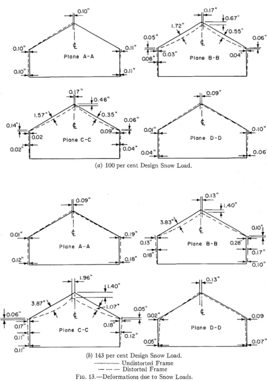
The next phase of loading consisted of the application of simulated snow loads which were applied in 25 per cent incre- ments of the design snow load of 50.8 lb per sq ft of horizontally projected area for the Ottawa area as determined from the 1953 edition of the National Building Code.
As a first increment, the console pres- sures were raised in the two pressure channels actuating the hydraulic rams on the roof to a load equivalent to a 50 per cent design snow load. After a period of sustained loading, the crack which had appeared in telltale No. 9 earlier in the
I Plane A - A I I 0.102 0.11" g . 1 0 " I Plane D - D I I I 0.04" 0 . 0 6 "
(a) 100 per cent Design Snow Load
0.01" -+I I P l a n e A - A Plane B - B 0.28"
r==f
I I --I-017" 0. 12: +%lo" Plane D - D I". . .
(b) 143 per cent Design Snow Load.
-- Ul~distortecl Frame
--- Distorted Frame
FIG. 13.-Deformations due to Snow Loads.
NOTES.-Refer to Figs. 5 and 7 for loading a ~ ~ d deflection points. Deformstio~ls are not clran,n to scale.
DOREY AND SCI-IRIEVER ON S I ~ T L A T E D WIKD AXD SXOW LOADS 43 test extended noticeably. The deforma-
tions were large in cornparisoll to those of previous loadings. As the loading was increased from 50 to 75 per cent of the design s~zo~v load many new cracks oc- curred in the telltales, and sounds of cracking could be heard in the house. At telltale No. 9, the exterior wall sepa- rated from the solid plaster partition to the extent of
+
in. near the ceiling. After hr of sustained loading, a further increase was made to 100 per cent de- sign snow load. This loading was sus- tained for approximately 1 hr withoutsuddenly, one a t the end of the house and one over the living: room and kitchen.
-
Asplice in the lollgitucliilal member at- tached to the underside of the collar ties had also given way. The break in the splice of the loilgitudiilal member and the buckling of the collar ties is shown in Fig. 14 and the failure of the two end collar ties in Fig. 15. An additional fail-
-
ure occurred in one of the rafters a t a knot. Except for a brief period of time during which failures were taking place in the roof assembly, it was possible to maintain stable console pressure forFIG. 14.-Failure in Splice of 1- by 4-in. T,ongitutlinal Member ant1 Buckling of Collar Ties in Attic under 143 per cent of Design Snow Load.
ally further serious damage. During the next increase from 100 to 125 per cent design ~ 1 1 0 1 ~ load, further sounds of dis-
tress were heard, and the increase in the deformations shown on the deflection chart indicated that a failure was im- minent. After
+
hr had elapsed, the snow loading was again increased, but before 150 per cent snow loading was reached the loading had to be stopped because of the large deflections occurring (Figs. 13 (a) and (b)).An inspection of the interior of the attic showed that all the collar ties were buckling horizontally to the extent of approximately 12 in. Under the maxi- mum load reached (143 per cent of the design snow load), two collar ties snapped
FIG. 15.-Failure of TJVO Collar Ties in the Attic a t one Entl of Test House under 143 pcr ccnt oi Design Snow Load.
approximately 1 hr at 143 per cent design snow loading. During this period of sustained loading, careful observations were made of the interior of the test house and photographs were taken of the damage to the interior fi~~ishes and to the roof members. When this illformation had been gathered, all loads were gradu- ally released and this phase of loading was completed.
No apparent damage resulted from wind loads (internal suction) equivalent to wind velocities up to 90 inph. The first crack in a telltale occurred when this loading to 90 mph was repeated. Further
cracks became visible when the loads were increased up to 120 mph. This cracking was more pronounced a t the junctions of the exterior wall and the solid plaster partitions than a t other par- titions.
The lateral movement under this wind loading was small (maximum 0.12 in.). The largest measured deflection in the rafters was 0.31 in. (outward at mid- span).
W i n d Loads-Internal Pressure:
During the application of the more severe conditions of wind loads with in- ternal pressure some of the existing cracks in the telltales were extended slightly.
The greatest deflection in the rafters for a wind velocity of 120 mph was 0.80 in. (outward a t the midspan). The great- est lateral movement in the exterior walls was 0.08 in.
One-half Design Snow Load plus W i n d Loads:
Under the combined loading of wind and snow there was no further signifi- cant damage caused to the test house. This condition of loading produced a reversal of the direction of loading on the roof because of the downward snow load- ing. As the wind loading was increased, the rafter deflections decreased because of the uplift of the wind on the roof. Consequently the largest deflections in the roof under the combined loading were inward and occurred at the lowest wind velocity simulated in the test.
Snow Loads:
As the snow loads were applied in the final phase of the loading test, the de- formations in the test house became more and more pronounced until failure began to occur in some parts of the roof a t 143 per cent of the design snow load of approximately 50 lb per sq ft so that
the load could not be increased any further.
At 100 per cent snow load the largest deflection in the rafters reached 1.72 in. on the front slope and 0.55 in. on the rear slope. The allowable deflection (NationalBuilding Code of Canada, 1953) for a rafter having a horizontally pro- jected span of 12 f t 2 in., is
&
of the horizontal projection of the rafter or 0.61 in., neglecting the support of- fered by the collar ties. Therefore, in the test, the allowable deflection was exceeded on the front slopes by 182 per cent a t design snow loading for this par- ticular roof slope. When failures occurred in the end collar ties and one rafter a t 143 per cent of the design snow load, the rafter deflections had reached values of 3.87 in. on the front slope and 1.07 in. on the rear slope in plane C-C and there was a total of 1.96 in. of displace- ment in the ridge board towards the front slope on this plane of deflections. The longitudinal 1 by P i n . member which was fastened to the underside of the collar ties was not attached to the gable ends nor, because of the central location of the chimney, was it con- tinuous over the full length of the house. Consequently as the snow load was in- creased, the collar ties were free to buckle in groups in each end of the house on opposite sides of the chimney, thus affording little support to the rafters after initial buckling had taken place. Figure 14 shows the failure of the splice in the longitudinal 1 by 4 i n . runner and the extent of lateral buckling.I n the interior of the house, damage became progressively larger as the snow load was increased, particularly at the intersection of interior partitions and exterior walls, where the exterior walls moved outward at eave level in most cases. This pattern of deformation was produced largely by the spreading effect of the deflecting rafters and by ineffec-
FIG. 16.-Plaster Telltale No. 4 After Completion of Test, Showing Extent of Cracking but no Signs of Separation Between Adjacent Walls.
tive resistance of the ceiling joist to this movement. Already a t 75 per cent of design snow loading the exterior wall and the solid plaster partition separated for a considerable distance from the ceil- ing down. Under further loading this separation grew larger. Although there was extensive cracking in the plaster telltales a t other points in the test house, there were no signs of apparent separa- tion a t the junctions of the conventional partition walls and exterior walls, as shown in Fig. 16. Further evidence of the spreading of the exterior walls is shown in Fig. 17 where the front wall moved outward between the conventional par- tition walls of the entrance and produced a fracture in the gypsum board ceiling.
Alterations to Roof to Increase Resistance to Stzow Loads:
As the relatively early failure of the FIG. 17.-Damage Caused to Ceiling Above
roof at 143 per cent of the design sllow Entrance by Spreading of Rafters Under Snow
load (or 72 lb per sq ft) seemed to be Load.
mainly the result of the compression in a simple manner the strength of the roof the collar ties, it was decided to alter could be improved. As a first possibility this part of the roof frame to find if in in preventing the buckling of the collar
ties the runner board of the collar ties was cross-braced in each half of the house on both sides of the chimney. The cross- bracing consisted of 1 by 6-in. members nailed to the underside of the collar ties. Then the simulated snow loading of the roof was repeated and a maximum load of 175 per cent of the design snow load was reached, an increase of 32 per cent. At this point, a failure occurred in two rafters and one collar tie, and the loads on the roof had to be released.
After reviewing the considerable gain in strength obtained from the bracing of the existing collar ties it was decided to go a step further and replace the rela- tively thin 1 by 4-in. collar ties by 2 by 4-in. members a t every second rafter, thus using no more lumber than before. These new collar struts were also cross- braced by a 1 by 4-in. runner and
1 by 6-in. cross-braces. The snow loading on the roof was then repeated again and a load of 206 per cent of the design snow load reached. At this point several rafters broke, two of which had been spliced after the earlier failure. Under this load, considerable further cracking in- side the house was observed and photo- graphs of all plaster telltales were taken. The vertical crack between the solid plaster partition and the outside wall was approximately
3
in. wide, indicating the outward movement of the walls under the thrust developed by the rafters.The results of the structural tests conducted by the Division of Building Research may be summarized as follows: Resista~zce to W i d Loads (Racking
Strengtl~):
The applicatioil of simulated wind loads (wind direction towards front of house only) corresponding to velocities up to 90 mph (design speed) and 120
rnph (approximately 80 per cent over- load) proved that the house was well capable of withstanding these loads.
The movements of the end walls (parallel to the wind) due to wind loads were small. This was shown both by the deflection measurements and by the fact that of the four plaster telltales in t h e corners of the house only one cracked (No. 5). I t was thus shown that the let-in
1 by 4-in. corner bracing, combined with the various finish materials, provided sufficient racking strength and that ex- terior wall sheathing was not required for additional racking resistance (if 1.8
times the design wind load is considered an acceptable test load).
Resistance to Snow Loads:
The application of simulated snow loads (symmetrical loading only, design load approximately 50 lb per sq ft) showed that the house in its original form could only carry 143 per cent of the design snow load and that, under 100 per cent design load, excessive deflections occurred in the roof structure. This indi- cated the following:
(1) Rafters.-The 2 by 4-in. rafters on 16-in. centers were structurally inade- quate. I t should be noted that these rafters do not meet the requirements of the National Building Code of Canada (1953) nor those of the present Building Standards of the Central Mortgage and Housing Corporatioil of Canada, al- though, for the latter, the 1 by 5-in. collar ties might be interpreted as inter- mediate supports and thus make the 2 by 4-in. rafters acceptable to those standards.
(2) Collar Ties.-The 1 by 5-in. collar ties were subjected to coinpressive loads (although their name implies a tension member). They were not able to resist these compressive loads effectively due to early buckling. T h e 1 by 4-in. longi-
tudinal runner attached to the under- Fztrbher Tests: side of the collar ties was of little value
in preventing them from buckling, be- The evaluation of the strength and cause it was not coiltinuous nor ade- rigidity of house structures is difficult quately braced against longitudinal because of their complexity of form, vari-
ations in materials, workmanship, movement.
After failure of the roof in its original method of construction, and many other form under 143 per cent of the design factors which make direct comparisons snow load the collar ties were altered to questionable. Before definite coilclusions make them "collar struts" without using can be reached, more information is more lumber by replacing the 1 by 5-in. needed and a number of structural tests members fastened to every rafter pair are necessary. The investigation carried by 2 by 4-in. members a t every second out on this experimental house has been rafter pair and cross-bracing. This in- the first step by the Division in obtaining creased the load-carrying capacity of the
roof by 63 per cent to 206 per cent of Future tests may be carried out in the
design snow load. I t appears that in this laboratory On full-scale test
form the collar struts can justifiably be houses rather than in the field, because of considered as intermediate supports for the amount of time and cost involved the rafters. in building up the test equipment around (3) Exterior Walls.-Under snow load- an existing house as was done in this ing separations began to occur a t the first test.
junction of the rear exterior wall and the
solid plaster partition walls under 75 per Ack~zowledgments: cent of design snow loading, indicating
that the thrust of the rafters tended to The authors wish to express their deflect the exterior side walls at thanks to all those whose time and effort the ceiling level at points where insuf- contributed to the successful completion ficient resistance was afforded by the of this project. To Mr. R. F. Legget, ceiling joists the interior cross parti- Director of the Division of Building tions. The connections between the rear Resarch, with whose approval this exterior wall and the interior solid plaster paper is published, acknowledgement is partitions were structurally inadequate gratefully made for his encouragement in preventing this separation. and assistance iu this project.
REFERENCES
(1) Central Mortgage and Housing Corpora- North Ryde, Sydney, N. S. W., No. l, tion, Bz~ilding Slandards (Excluding Apart- June 1946.
ment Buildings), Ottawa, Canada. Re- (4) J. A. P. Laurie and Charles A. Rigby,
printed April 1954. "Some further Investigations into the
(2) Housing and Home Finance Agency, Per- Structural Requirements of Single Storey
.forn~nltce Standards (Structural and Insula- Urban Bantu Houses," Brrllelin South tion Recluirements for Houses), Housing African Council for Scientific and Industrial and I-Ioinc Finance Agency Technical Research, Pretoria, South Africa, No. 12, Office, Washington 25, D. C. June 1947. June 1954.
(3) David J. Isaacs, "The Structural Suffi- (5) Ministry of Worlrs, "House Construction," ciency of Domestic Buildings," Birllelin Post-War Building Studies No. 1, His Departmeilt of Works and Housing, Com- Majesty's Stationery Office, London (1944). n~on~vealth Experimental Building Station, (6) Ministry of Worlts. "House Construction,"
Post-War Building Studies No. 23, His Majesty's Stationery Office, London (1946). (7) N. D. Nathan, "Structural Requirements of Single-Storey Native Houses," Btdleti7z South African Council for Scientific and In- dustrial Research, South Africa, No. 9, Dec. 1952.
(8) "National Building Code of Canada 1953," National Research Council, Canada, Ottawa (1953).
(9) A. Short and L. G. Simms, "Survey of Loading Tests on Some Post-War Proto- type Houses," The Strzrct~~ral Engineer,
Feb. 1949, pp. 67-98.
(10) F. G . Thomas, "Structural Engineering Research a t the Building Research Sta- tion," The Strzrctural Engineer, Vol. XXVI, No. 2 (1948).
(11) F. G. Thomas. "Structural Requirements for Houses," Special Report, No. 1 Depart- ment of Scientific and Industrial Research, National Building Studies (1948). (12) U. S. Naval Civil Engineering Research
and Evaluation Laboratory, "Evaluation of a 40-ft by 100-ft Arch Rib Prefabricated
Metal Utility Building," Final Tecl~rzical
iMentora7zdz~1>z M-039, Port Huenerne, Calif. May 1, 1952.
(13) U. S. Naval Civil Engineering Research and Evaluation Laboratory, 'LEvaluation of a 40-ft by 100-ft Frameless Straight Sided Prefabricated Metal Utility Build- ing," Final Tecl~tzical Menzorandt~vz M-050,
Port Hueneme, Calif., April 1, 1952.
(14) U. S. Naval Civil Engineering Research and Evaluation Laboratory, "Evaluation of a 20-ft by 48-ft Arch Rib Prefabricated Metal Barracks Building," Final Tech-
nical Menzorandz~nz M-055, Port Hueneme, Calif., April 1, 1952.
(15) H . L. Whittemore and Arnbrose H. Stang, "Methods of Determining the Structural Properties of Low Cost House Construc- tion,'' National Bureau of Standards, Building Materials and Structures, Report No. 2, Aug. 10, 1938.
(16) C. S. Yeates, "The Application of Testing Methods t o Modern Building Techniques,"
Engineering Inspection, Vol. 12, No. 4, pp. 4-25, (1948).
DISCUSSION MR. T. K. M~y.l-The framing mem-
bers, of course, are the principal concern. Would the authors describe the framing members as being of high-grade, average- grade, low-grade or mixed grades of lumber?
MR. W. R. SCIBIEVER (author).- They were of average grade.
As I mentioned in the beginning, no special attempt was made to differ in any way in this house from the ilormal construction methods used in our area.
CHAIRMAN ROBERT F. LEGGET."&~~Y
I ask what species?
MR. SCHRIEVER.-P~~~.
MR. R . F. BARTELMES.~-T~~ authors mentioned 120 mph resistance capability
1 Director of Technical Servicc, Wcst Coast
Lumbermen's hssn., Portland, Ore.
2 Director of Building Research, Natio~lal Research Cour~cil of Canada, Division of Builcl- ing Research, Ottawa, Ont., Canada.
3 Chief, Building Design Branch, Civil Engi- neering Dept., U. S. Corps of Engineers, Re- search and Develop~nent Lab., Fort Bclvoir. Va.
for the building, that is on the framing. What was the method of cleating the siding on to resist suction pulls?
W ~ R . SCHRIEVER.-W~ did not investi- gate the resistance of the cleating to that suction. Originally we were trying to include a study of this factor by attach- ing the roof bearing pads on the alumi- num by gluing. However, during the test we found that the glue which we had used was not able to resist the pull of the bear- ing pads and, to end our troubles of re- pairing the pads all the time, we finally drilled through the roof and used wire loops which went around the bearing pads and rafters.
MR. L. J. ~ ~ I A R K W A R D T . " - ~ ~ ~ S the effect studied on deformation of revers-
ing the stresses by changing thedirectioll of the loading?
MR. SCHRIEVER.-x~. We applied it
'
-4sst. Directo~. Forest Products Lab., Forest Service, U. S. Dept. of Agriculture, Madison, Wis.only from one direction. The only re- versal we did was from wind load to snow load.
MR. R. F. L u x ~ o R ~ . ~ - W a s the in- terior wall covering wet plaster construc- tion or was it dry wall construction?
MR. SCHRIEVER.-It was dry wall con- struction.
MR. LUXFORD.--Did YOU use tape
over the joints?
MR. SCHRIEVER.-Yes, I believe all joints were taped.
MR. IRA ASHFIELD.~-I~~ reply to Mr. Luxford's question, gypsum wall board with standard cement joints and paper tape was used with the one exception that there is the plaster partition.
IMR. LUXFORD.-I was speaking of ex- terior walls.
MR. A S H E I E L D . - T ~ ~ ~ were gypsum board on wood studs.
MR. JOHN F. LEWIS.~-I was con-
cerned with the roof bracing system shown in Figs. 2 and 14. The use of collar ties is not particularly conven- tional to Southern California or to build- ing codes and housing agencies in the
Head. Housing Section, Forest Products Lab.. Forest Service, U. S. Dept. of Agriculture, Madison, Wis.
Supervisor, Building Materials Dept., Cen- tral Mortgage and Housing Corp., Ottawa, Ont., Canada.
Structural ltesearch Engr., Dept. of County Engineer, Building and Safety Div., County of Los Angeles, Los Angeles, Calif.
States, and I wondered if that was a typical system used in Canada, or if it was tested in that way as an experimen- tal basis of determining whit might happen with just the collar ties. Conven- tional framing to me is made of struts and kickers and complicated bracing system that we see in most housing projects.
MR. ASHFIELD.-I do not accept the blame for the design, but I can report about it.
We selected this particular system because it was the lightest of three or four methods which were in reasonably common use, and we wanted to find out how it would perform. I think the au- thors have reported on that.
CHAIRMAN LEGGET.-AS a result of this work, the Division of Building Re- search has embarked on a very extensive program of study of standard Canadian roof frame designs for house structures, as one of the several by-products of this work.
MR. J. E. DYKINS?-I would like to ask Mr. Ashfield what nail spacing was used on the wallboard?
MR. AsHr1ELD.-We followed the manufacturers' directions, and I believe the nails were 6 to 9 in. apart.
8 Project Engineer, Environmental Division, U. S. Naval Research Establishment, Port Hueneme, Calif.