* /j i.N
A Constraint-Based System for the
Design and Evaluation of Precision Machine Tools
by
Bradley S. Homann
B.S. Aerospace Engineering (1994) Embry-Riddle Aeronautical University, Prescott
SUBMITTED TO THE DEPARTMENT OF MECHANICAL ENGINEERING IN PARTIAL FULFILLMENT OF THE REQUIREMENTS OF THE DEGREE OF
MASTER OF SCIENCE AT THE
MASSACHUSETTS INSTITUTE OF TECHNOLOGY JUNE 1997
© 1997 Massachusetts Institute of Technology All Rights Reserved
Signature of Author:_
,'
Department of Mechanical Engineering May 9, 1997
Certified by: --- ....
-s' oAnna Thornton
Assistant Professor of MeCbtlanical r•,n
-'.--Accepted by:
Ain A. Sonin Chairman, Department Committee on Graduate Students
A Constraint-Based System for the
Design and Evaluation of Precision Machine Tools
by
Bradley S. Homann
Submitted to the Department of Mechanical Engineering on May 9, 1997
in partial fulfillment of the
requirements for the Degree of Master of Science
ABSTRACT
Evaluation and optimization of precision machine tool concepts is a complex process. Most concepts are evaluated against existing machines and past design experiences, with little or no attention paid to formalized analysis methods. When formal methods are used, they are too time consuming to apply to more than one or two concepts. This results in an evaluation process where superior concepts are often overlooked or dismissed, resulting in inferior machine tool or costly modifications to a design late in the design cycle.
The lack of efficient formal methods has arisen from the belief that machine tool error motions are non-deterministic. While coupling does make prediction of error motions difficult, the majority of error motions resulting in tool-workpiece errors can be accounted for through the use of an error budget. This dissertation presents a computational tool for the rapid
evaluation and optimization of precision machine tools based on parametric modeling of a given concept. Components common to many machine tools are incorporated into standard libraries, and the error motions and common design constraints associated with these components are captured within the component description. A machine design concept is defined in terms of these standard components, with interactions between the various components accounted for by standard interfaces between compatible components. Total tool-workpiece interaction errors are determined through the use of an error budget based on the Homogeneous Transformation Matrices. Design constraints are set with respect to any variable in the system, and
optimization with respect to any subset of these constraints may be performed.
This results in an application that can be used to rapidly model, analyze, and optimize a series of precision machine tool concepts. Standard components may be incorporated into a variety of concepts, allowing rapid modeling of a given concept and avoiding the cost of completely respecifying the machine model every time the concept is altered. This increase in speed allows for an increased number of concepts to be evaluated, and the ability to optimize the conce ven set of design constraints ensures a higher quality concept. This results .in an in iegn solution space and reduces the chance that a superior concept will
ual design phase is ended.
Thesis Supervisor: Anna Thornton
Title: Assistant Professor of Mechanical Engineering
Abstract
Acknowledgments
My time at M.I.T. has been vaguely reminiscent of the 1997 Grand Prix of Monaco: lots of curves, no straitaways, plenty of rain, and an ending that seems a few laps premature. As in racing, individual success at M.I.T. requires the support of many people. Without their help and guidance, I would have never completed my work, or had the opportunity to thank them for their contributions to my education.
Many thanks to Leslie Regan for her constant support and concern. A brief visit to the graduate office always provided a bit of sanity and restored my motivation (in addition to keeping me out of trouble).
Thanks also to Dan Frey, for his willingness to stop whatever he was doing to help me solve my machine design problems. Dan's input cleared up more than a few problems, and provided valuable information that just doesn't seem to make it into papers or textbooks.
To all of my friends, thanks for all the good times, and the support through the bad. It's been a great two years.
Of course a big thanks to my advisor, Anna Thornton. Her input and guidance (and funding) got me started in this project and kept me pointed in the right direction. Most importantly, Anna never forgot than management is more than deadlines, schedules, and money, and for that I owe her big time.
Last, to mom and dad (who started this whole thing), thanks for many years of support, love, and understanding. You guys are the best.
Brad Homann M.I.T.
May, 1997
Table of Contents
Title Page ... ... 1 Abstract ... 2 Acknowledgments ... 3 List of Figures... ... 7 List of Tables ... 9 1.0 Introduction ... 10 1.1 Background ... 101.2 Overview of Precision Machine Tools ... 13
1.2.1 Accuracy, Resolution, and Repeatability ... 13
1.2.2. Error Budgets ... 15
1.2.3. Abbe Error... 16
1.2.4. Sensitive Directions... ... 16
1.3 Overview of Precision Machine Design ... ... 18
1.3.1 Development of New Machines ... ... 18
1.3.2 Modification of Existing Machines ... 21
1.4 Existing Software for Precision Machine Design ... 22
1.4.1. Specific Machine Tool Design Applications ... 23
1.4.2. Applications for the Simulation of Machine Tool Assemblies...24
1.5 Research Overview ... ... 24
2.0 Principles of Machine Tool Error Calculations... 28
2.1 Introduction... ... 28
2.2 Sources of M achine Tool Errors ... 28
2.2.1 Geometric Errors ... ... ... ... 28
2.2.2 Therm al Errors... ... 32
2.2.3 Loading Errors... ... 33
2.2.4 Dynamic Errors... ... 34
2.2.5 Summary of Error Motions... 35
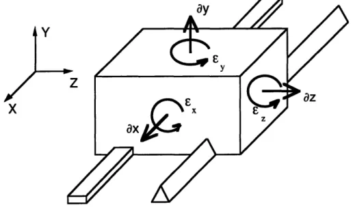
2.3 Error Motion Representation ... 36
2.3.1 Fixed Fram e... ... 36
2.3.2 Rotating Frame ... 37
2.3.3 Coordinate Frame Location... .... 37
2.4 Error Propagation and HTM Representation ... 38
2.4.1 The Homogeneous Transformation Matrix ... 38
2.4.2 The Kinematic Machine Model ... 40
2.5 Machine Modeling and the System Error Budget ... 43
2.6 Example of the Machine Tool Design Process...45
2.6.1 Specification of Machine Requirements...45
2.6.2 Conceptual Development ... 45
2.6.3 Conceptual Evaluation ... 46
2.6.4 Example Summary ... 48
2.7 Chapter Summary ... ... 51
3.0 Constraint-Based Design Methods ... 52
3.1 Introduction ... 52
3.2 Design Constraint Methodology...53
3.2.1 Equality Constraints ... 54 3.2.2 Inequality Constraints ... ... . ...55 3.2.3 Continuous Constraints ... 56 3.2.4 Discrete Constraints ... 57 3.2.5 Constraint Network ... 57 3.3 Sources of Constraints ... 58 3.3.1 Theoretical Relationships ... ... 59 3.3.2 Physical Characteristics ... 59 3.3.3 Empirical Information ... 60
3.3.4 Heuristics / Design Knowledge ... .. 61
3.4 Constraint Example ... ... 62
3.5 Chapter Summary ... 66
4.0 PMDA - Object Representations ... 67
4.1 Introduction ... 67
4.2 Requirements of PMDA Objects ... 68
4.2.1. Component-Specific Parameters ... ... 68
4.2.2 Component-Connectivity Information ... 74
4.3 Object Hierarchy and Representations ... .. ... ... ... 76
4.3.1 O verview ... 77 4.3.2 Support Objects ... 79 4.3.3 Component Objects...83 4.3.4 Interface Objects ... 88 4.4 Chapter Summary ... ... 90 5.0 PMDA - Functionality ... 91 5.1 Introduction ... 91 5.2 PMDA Overview ... 91
5.3 Kinematic Machine Modeling... ... 92
5.3.1 Creation of the Kinematic Model ... 93
5.3.2 HTM Calculation ... 93
5.4 Error Motion Modeling and Evaluation...94
5.4.1 Error Motion Representation ... 94
5.4.2 Determination of Total Tool-Workpiece Interaction Error ... 97
5.5 Constraint Evaluation ... 99
5.6 Concept Optimization ... ... 100
5.7 User Interface...100
5.8 Chapter Summary ... 101
6.0 PMDA - Example Cases ... ... 102
6.1 Introduction ... 102
6.2 The Rotary Bearing Object ... 102
6.2.1 The Rotational Motion Bearing ... 102
6.2.2 The Rotary Bearing Template Object ... 104
6.2.3 The NTN Rotary Bearing Object ... 110
6.2.4. Summary ... 112
6.3 Case Study -A Simple Machine Spindle ... 112
6.3.1 Component Selection...14
6.3.2 Spindle Modeling ... ... ... 117 I able of contents
6.3.3 Kinem atic M odeling ... 117
6.3.4 Error Motion Modeling ... .... 117
6.3.5 Constraint Evaluation ... 120
6.3.7 Conclusion ... 124
6.4 Chapter Sum m ary ... 124
7.0 Conclusions ... 127
7.1 Sum m ary of W ork ... 127
7.1.1 Kinematic Machine Modeling ... 127
7.1.2 Error Motion Modeling and Evaluation ... ... 128
7.1.3 Constraint Evaluation ... 128
7.2 Analysis of Approach...128
7.2.1 Advantages of the PMDA Approach ... 128
7.2.2 Disadvantages of the PMDA Approach ... 129
7.3 Future Research ... ... 129
7.3.1 Short Term Research ... 129
7.3.2 Long Term Research ... ... 130
7.4 Conclusion ... .... 131
Bibliography... 132
A. Sample Case... 134
A.1. Component and Interface Objects...134
A.2. Sample Case Second Run ... ... 134
A.3. Sample Case Output Files ... ... 134
B. Error Motion Modeling... 145
B.1 Error Motion Representations in PMDA ... 145
B.2 Inclusion of Error Motions in PMDA Objects...145
B.3 Calculation of Error Motions in PMDA Structural Loops ... 149
C. Kinematic Modeling ... 151
C.1 HTM Calculation ... 151
C.2 Structural Loops ... ... 151
D. Input and Output Files ... 155
D .1. Input Files ... ... 155
D.2. Output Files ... 156
D.3. Sample Input and Output Files ... 158
List of Figures
Figure 1.1: Example of Design Constraints ... 13
Figure 1.2: Accuracy, Repeatability, and Resolution... 14
Figure 1.3: A bbe Error ... 16
Figure 1.4: Comparison of Sensitive vs Non-Sensitive Directions... 17
Figure 1.5: General Product Design Cycle ... ... 1 9 Figure 1.6: Process for Modification of Existing Machine Tools ... 22
Figure 1.7: Overview of the Precision Machine Design Assistant... ... 25
Figure 1.8: PMDA in the Machine Tool Design Cycle ... ... 26
Figure 2.1: Examples of Common Geometric Errors ... ... 29
Figure 2.2: Surface Finish and Straightness Errors... ... 30
Figure 2.3: Parallelism and Perpindicularity Error... ... 31
Figure 2.4: Example of Uniform and Non-Uniform Thermal Errors ... 33
Figure 2.5: Fixed Reference Frame Representation...36
Figure 2.6: Rotating Reference Frame Representation ... .... 37
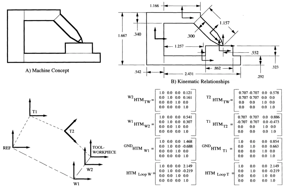
Figure 2.7: Example of HTM Modeling ... 42
Figure 2.8: Sample Machine Tool Proposal... ... 45
Figure 2.9: Sample Machine Tool Concepts ... ... 47
Figure 2.10: Concept with Specified Components... ... 48
Figure 2.11: Sample Toolpoint Error Motion ... ... 49
Figure 2.12: Example of Toolpoint Error Prediction ... ... 50
Figure 3.1: Examples of Exact and Inexact Constraints ... 55
Figure 3.2: Example Constraint Network... 58
Figure 3.3 Example of Empirical Information... ... 61
Figure 3.4: Constraint Example for a Thin-Walled Pressure Vessel ... 63
Figure 4.1: Linear Error Motion Representation Example... ... 73
Figure 4.2: Example of Shared Performance Information ... 76
Figure 4.3: Shaft Template and Catalog Objects ... ... 78
Figure 4.4: Equation Tree Representation ... ... 81
Figure 4.5: Standard Rotational Bearing ... ... 85
Figure 4.6: Standard Single-Diameter Circular Shaft... ... 86
Figure 4.7: General Rotary Motion Chuck ... 86
Figure 4.8: Simple Single-Point Cutting Tool ... ... 87
Figure 5.1: PMDA Modeling Process ...92
Figure 5.2: HTM Calculation Process... 95
Figure 5.3: Error Motions in PMDA ... 96
Figure 5.4: Inner Ring Radial Runout Modeling ... ... 96
Figure 5.5: PM DA User Interface... 00
Figure 6.1: Rotary Bearing Object Hierarchy ... 03
Figure 6.2: Required Rotational Motion Bearing Design Information ... 104
Figure 6.3: The Rotary Bearing Template Object... ... 105
Figure 6.4: Rotary Bearing Constraints ... 06
Figure 6.5: Rotary Bearing Error Motions ... 18
Figure 6.6: Rotary Bearing Error Motion Modeling ... 109
Figure 6.7: The NTN Rotary Bearing Object ... 111
Figure 6.8: A Simple Machine Tool Spindle ... 113
Figure 6.9: Common Machine Spindle Error Motions...13
Figure 6.10a: Simple Machine Spindle Model ... 115
Figure 6.10b: Structural Loops for the Simple Machine Spindle ... 16
Figure 6.11: HTMs for the Simple Machine Spindle ... 18 List of Figures
Figure 6.12a: Toolpoint Displacement Errors for the Simple Machine Spindle...1...21
Figure 6.12b: Axial Displacement Errors for the Simple Machine Spindle ... 1.... 22
Figure 6.12c: Radial Displacement Errors for the Simple Machine Spindle ... 123
Figure 6.13: Constraints for the Simple Machine Spindle... 25
Figure A.1: Sample Case Component Objects...35
Figure A.2: Sample Case Interface Objects ... 36
Figure B.1: Geometry of PMDA Error Motions ... 146
Figure B.2: PMDA Error Motion Equations ... 47
Figure B.3: Sample Error Motion Output ... 48
Figure B.4: Process for Calculating Error Motions in PMDA Objects... 149
Figure B.5: Error Calculation Procedure ... 50
Figure C.1: Procedure to Calculate HTMs between Arbitrary Systems ... 1...52
Figure C.2: Example of Structural Loops ... 53
Figure C.3: Structural Loop Representation in PMDA... 54
Figure D.1: Sample PMDA Catalog Record ... 156
Figure D.2: Sample PMDA Material Data File Record... 57
Figure D.3a: Toolpoint Displacement Errors for the Simple Machine Spindle... 171
Figure D.3b: Axial Displacement Errors for the Simple Machine Spindle... 72
Figure D.3c: Radial Displacement Errors for the Simple Machine Spindle ... 1...73
List of Tables
Table 3.1 a: Design Variables for Iteration 1 ... . ... 65
Table 3.1b: Constraint Evaluation for Iteration 1 ... 65
Table 3.2a: Design Variables for Iteration 2 ... 66
Table 3.2b: Constraint Evaluation for Iteration 2 ... 66
Table 4.1: Infix and Postfix Equation Representations... ... 81
Table 6.1: Error Motion Values for the Example Machine Spindle ... 120
Table A.1: Error Motion Values for the Sample Case -Run #2 ... 138
1.0 Introduction
1.1 Background
A machine tool is an integrated collection of mechanical components operating in a coordinated fashion in order to position a cutting tool with respect to a workpiece. Material is then removed from the workpiece until the desired part geometry is achieved. While the design and characterization of the individual components in a machine tool is a relatively mature field, the design, evaluation, and optimization of integrated machines is not. This is especially true at the conceptual level of design, where the majority of features, operational characteristics, and costs for a given machine are set. Berliner and Brimson [1991] state that up to 80% of the total
life-cycle cost of a product is set during the conceptual stage of design. The need for increased accuracy, repeatability, and resolution, as well as a desire to decrease design cycle time and increase efficiency of the overall design process, has led to a re-evaluation of the methods used in the conceptual design of machine tools.
Traditionally, the dominant factor in the success of a machine tool design was the skill and experience of the individual designer or design team [Slocum, 1992]. Engineers and skilled machinists would develop new machine concepts based on heuristics and past design experience. Concepts were then modified and evaluated until a single concept was selected by the team for further development. Throughout the evaluation phase, basic theory or
computational simulation are often ignored or used sparingly. The use of computational tools was limited to CAD drawings in the detailed stages of design, or simple calculations for individual component sizing or reaction force prediction. The use of more advanced
computational techniques is limited to the detail design phase, when the geometric topologies and major operating characteristics of the machine are set. While this approach was viable for the most preliminary stages of development, any problems not identified by the design team at
the conceptual level could result in a machine tool requiring expensive re-working, hand-fixturing, or modification.
The above inadequacies are a result of an incomplete exploration of the design space for the given machine tool design problem. Chan [1987] points out:
Due to the constraints on time and resources, as well as the limited expertise available in an organization, designers are used to considering only one or two alternative. This procedure always results in a situation where a superior concept appears in the subsequent stages, but it is too late or too costly to implement it.
The solution with respect to machine tool design is to provide designers with a comprehensive product for the rapid evaluation and optimization of design concepts. By increasing the
number of concepts evaluated, the solution space is expanded and the opportunity for selection of improved concepts is increased. Unfortunately, computational tools allowing for the rapid evaluation of machine tool concepts do not exist, and the lack of suitable algorithms has precluded the creation of tools useful at the conceptual level. For this reason, current design methods continue to rely on heuristics and the experience of the design team.
A relatively new trend related to machine tool design is the retrofitting of existing machines with new, more accurate components. This process allows existing hardware to be used in order to avoid the investment of a new machine. For example, the replacement of gear-driven actuators on an existing milling machine with linear motors can increase the accuracy of the machine while avoiding the cost of purchasing a new milling machine and reducing
maintenance costs. While the design and integration of these new components offers a much different challenge that the design of a completely new machine, the methods for evaluating these modifications is similar to the HTM approach described above. The influence of existing machine errors and operational conditions must be accurately accounted for, and the new components must be selected to ensure proper operation with existing components. As with constraint-based design (discussed above), formal tools and methods for the retrofitting of machine tools do not exist, and designers must still rely on experience and intuition for many retrofitting decisions.
The above approach for machine tool design arose from the belief that interactions between the components comprising a machine tool were not deterministic or predictable. However, while some aspects of machine tool behavior are not well understood, the majority of influences on overall machine errors are deterministic and can be predicted. Bryan [1984] states:
The basic idea is that machine tools obey cause and effect relationships that are within our ability to understand and control and that there is nothing random or probabilistic about their behavior. Everything happens for a reason and the list of reasons is small enough to manage.
Recent improvements in design methods propose basic machine error simulation and concept evaluation through the use of machine modeling via Homogeneous Transformation Matrices (HTM) on a component-by-component basis. By modeling each component as a rigid body, including the component errors in the local component coordinate frame, and then transforming these errors to a reference coordinate system, the total tool-workpiece interaction error for a given machine tool concept may be accurately predicted for a variety of operating conditions.
Errors that are easily accounted for, such as elastic beam-bending or thermal
deflections, are determined theoretically, while more difficult or esoteric errors, such as joint interactions or complex dynamic errors, may be predicted and included based on experience or empirical data. This allows designers to evaluate a concept against the total allowable errors (error budget) for the machine. By directly comparing the errors associated with each proposed concept versus the error budget, a designer may determine the performance of a particular concept or compare a series of concepts against each other. This allows the designer to expand the solution space and evaluate concepts based on sound engineering theory, and avoids the need for decision-making based purely on intuition or experience.
While the above method allows for reasonable predictions of machine tool errors, the process for developing an HTM model is a complex and time consuming process [Frey, 1997]. Spreadsheet programs or general mathematical software is used for almost all necessary
calculations and simulations; currently no commercially-available software packages allow for the explicit creation of HTM models. Any modification to the design concept requires
extensive modification to the HTM model, and evaluation of independent concepts requires independent models. Information on component error motions, accuracy, or expected
performance must be included manually, and comparison of individual components performing the same operation also require remodeling by the designer.
Another shortcoming of existing machine tool design methods is the lack of design optimization. To thoroughly evaluate several machine concepts, the effect of many factors, such as catalog-based parts, limitations on cost, or ease of manufacturability, must be included. These factor can be seen as a series of constraints on the design, and optimization subject to a complete set of constraints for a given concept yields the optimum design for that concept. While most traditional design methods are based on the definition and satisfaction of
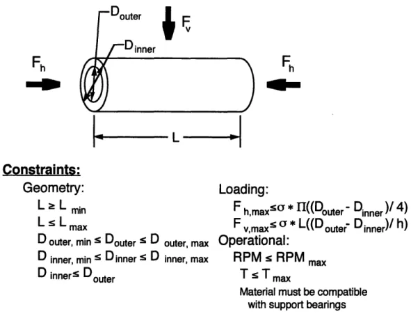
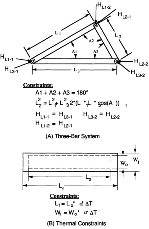
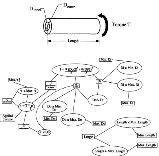
constraints, it is impossible to include all but the major constraints for a given machine concept without the assistance of computational methods. For example, the simplified connecting rod shown in Figure 1.1 requires 9 constraints to partially limit the design to a feasible design space. Increased complexity of the part, inclusion of other factors besides those listed, or a more complete limitation of the design space will result in a dramatic increase in the number of required constraints; as a result, non-computational methods become impractical or impossible. Unfortunately, few constraint-based design tools exist outside of the research environment, forcing the machine tool designer to invest the time necessary to develop an application in-house, or not leverage constraint-based methods.
Fh
LL
Constraints:
Geometry:
L L minL L
max
D outer, min r Douter r D outer, max D inner, min s Dinner s D inner, max
D inner< Doute r
~4]
ding:
h,maxSon * H((Douter - Dinner )/ 4)
v,maxs o * L((D outer Dinner)/ h)
rational:
PM < RPM max
TsT max
Material must be compatible with support bearings
Figure 1.1: Example of Design Constraints
Recent advances in object-oriented architecture provide an opportunity for the automation of the evaluation and optimization process for machine tool concepts. By encapsulating machine tool component information in computational objects, the majority of engineering information necessary for the development of computational methods for machine design may be stored and accessed as needed. The following sections provide a more detailed overview of the existing machine tool design and retrofitting process, and offer some insight into the challenges facing machine designers.
1.2
Overview of Precision Machine Tools
1.2.1 Accuracy, Resolution, and Repeatability
The performance of a given machine tool is often measured by three quantities:
accuracy, repeatability, and resolution. By classifying machines by these three quantities, the designer may directly compare the performance of a series of machines, or evaluate a specific Chapter 1: Introduction
concept against the required tolerances of the machined part. Figure 1.2 contains a graphical explanation of these three quantities.
Resoli
us of RMS Circle
Repeatability
MS Circle of sucessive fttempts to reach :eal point RMS Circle of sucessiveattempts to reach ideal point plus mimum step size
ideal position
Figure 1.2: Accuracy, Repeatability, and Resolution
Accuracy is defined as the maximum error between any two positions in the working volume of the machine. For example, the accuracy of a Coordinate Measuring Machine (CMM) may be determined by programming the probe to translate to a certain location. The difference between the programmed location of the probe (measured with respect to a base coordinate system) and the actual probe location is the accuracy of the machine. Accuracy may be defined in terms of translational or rotational error motions, and if often measured at various locations within the working volume of the machine to determine variations in accuracy with respect to location within the volume.
Repeatability is the error between successive attempts to position the tool at a given location in the working volume. The maximum deviation between any of a series of attempts is the total repeatability of the machine. Because of the nature of the measurement, repeatability is often referred to in terms of probability of tool placement within a certain limit of the ideal (desired) location. Repeatability may be classified in terms of uni-directional or bi-directional approaches, with the latter accounting for backlash, hysterisis, and other directional effects.
Resolution is a measure of how precisely the machine can be controlled. The largest of the smallest programmable step sizes is the resolution of the machine. Resolution may be
thought of as a measure of the ideal performance of the machine, since the machine cannot achieve a smaller step size without the influence of errors in the individual components of the machine.
A precision machine tool differs from a standard machine tool in the tolerances placed on the above quantities. While there is no defined point for transition between standard and precision machines, the use of "precision" implies the ability to achieve tighter tolerances and a desire for highly accurate final part geometries. A typical number used to define the precision necessary for classification as a precision machine tool is an accuracy of 5.0 Rm or greater
[Frey, 1997]. Any machine tool accurate to this general limit may be thought of as a precision machine tool.
1.2.2. Error Budgets
One method of defining and evaluating the performance of a machine tool concept is through the use of an error budget. An error budget allows the designer to assign values to the errors associated with each component and determine the overall effect of these component errors on the total error at the tool-workpiece interface point. This result is then compared to the desired performance of the machine, and modifications to the machine concept are made if the error are considered unacceptable. The components most heavily influencing the tool-workpiece error may also be determined through the error budgeting process, allowing for concentration on the "problem areas" of the machine. Limits on best and worst case machine performance may also be determined by varying the performance of the individual components in the machine.
The first step in creation of an error budget is to develop a mathematical model of the complete machine tool. Each component is modeled as a rigid body, with the geometric relationships between components described by Homogeneous Transformation Matrices
(HTM) . The details concerning HTM modeling are described in Section 2. Once the model is completed, errors associated with each component are included and the effect on the tool point location (with respect to the workpiece) is determined. Total machine performance is
determined by including all of the individual component errors at once, while the effects of each component can be determined by including the errors of each component individually. Upper and lower bounds on the error estimates for the machine may be determined by altering the individual component errors for best and worst case performance. Optimization of the
concept takes place through the iterative process of evaluating the machine model and modifying the errors of each component until the desired level of performance is achieved.
As stated above, the major drawback of an error budget is the effort and time required to construct the machine model. A typical HTM model for a precision machine tool can require up to one month to construct and test [Frey, 1997]. Any changes made to the concept must be reflected in the model, and even small changes in the concept could result in major
modifications requiring days to implement. Because of this, many designers avoid error budgets and rely on intuition and experience to evaluate concepts, or develop overly-simplistic error budgets of limited value. This practice often results in an inadequate investigation of a concept, and increases the chance that a problem in the design will not be corrected, or that a
superior concept will not be selected for further development.
1.2.3. Abbe Error
Abbe error is the amplification of an error by a lever arm [Slocum, 1992]. A graphical example of Abbe error (also referred to as parallax error) is shown in Figure 1.3. In this example, a relatively small deflection at the bearing results in a large deflection at the end of the shaft. For this reason, Abbe error effects must be considered in the evaluation of any machine tool concept, and efforts must be made to minimize the amplification of errors due to a lever
arm.
ideal error in
ifAUI
Abbe Error acap to
I
Figure 1.3: Abbe Error
An HTM-based error budget will account for Abbe error and allow the designer to determine which components are affected by or result in angular amplifications. For the conceptual design phase, however, a designer should attempt to develop concepts that are not sensitive to or dominated by Abbe effects.
1.2.4. Sensitive Directions
Tool-workpiece interaction errors are often described in terms of displacements and rotations in a coordinate frame attached to the tool. Figure 1.4 shows an example of these
Chapter 1: Introduction
Non- Sensitive Direction Direction
sensitive ideal
sensitive
For: A sensitive =
A
non-sensitiveA Dsensitive =8.4 *A Dnon-sensitive
Figure 1.4: Comparision of Sensitive vs Non-Sensitive Directions errors for a tool-workpiece interaction for a simple metal lathe. The effect of two of these errors on the part is also shown in the figure. While both errors are assumed to be of equal magnitude, the resulting workpiece errors are not. In this example, a displacement along the Z-axis of the cylinder of magnitude A results in a workpiece of diameter (Dideal - 2A). A
displacement along the Y-axis of A, however, results in a diameter of (Dideal + (0.24*A)). The error along the X-axis results in no diameter variation, and is also considered non-sensitive. This would not be the case, however, if the cutting tool was to remove material up to a specific
point on the workpiece.
The above example illustrates the concept of sensitive directions. A sensitive direction is one in which an error motion of the tool will result in a substantial workpiece error (in terms of the total workpiece error). Analysis of sensitive directions provides an indication of what errors a designer should concentrate on; reducing A in the above example would result in more accurate parts, while reducing B will have little effect on part accuracy (for the above example). For this reason, errors in non-sensitive directions may be neglected, and unnecessary
modifications may be avoided. In practice, all errors are included in the error budget and sensitive directions are accounted for after the total error is determined. For conceptual development a designer must be aware of the issues of sensitive directions and avoid any designs that would result in an increase in sensitive-direction errors.
1.3
Overview of Precision Machine Design
This section covers the existing methods for the development of precision machine tools. Topics include the process for design of new machines, the process for remanufacture and retrofit of existing machines, and the software tools currently available for use in precision machine design. An example of the complete machine tool design process, as well as the development and evaluation of an error budget, is presented in Chapter 2.
1.3.1 Development of New Machines
The design cycle for a new machine begins with the establishment of s set of operations or functions the machine will be required to complete. Once the required functions are
identified and refined, and a target market is set, the design team develops a series of concepts capable of meeting the requirements. After successive iterations and evaluations of the
concepts, the team selects one design for detail development and production. Prototyping and production phases follow. The design cycle is considered complete when the production run of the machine is concluded or no further modification to the machine is allowed. The individual phases of the design cycle are shown graphically in Figure 1.5.
Concept Development
The starting point for a machine design is the conceptual design phase. During this phase, the design team attempts to coalesce current technology into a machine that will satisfy all of the prescribed functional requirements. Ulrich and Eppinger [1995] describe a concept as
Determine
Customer
Needs
Concept Development
Develop Specificaitons Develop Concepts to
for New Product meet Specifications
Concept 1 Concept 2. .. Concept N
Detail Design
Develop concept inFinal Product
:ept
Evaluation
.lect Concept for Detail Design
Figure 1.5: General Product Design Cycle
"a description of the form, function, and features of a product [p 16]". It is during this phase that the majority of major design decisions concerning the overall shape, function,
performance, and cost of the machine will be made.
Concept development includes the determination of the overall size and layout, required degrees of freedom, and number and basic type of bearings, actuators, and drive components. Other factors, such as part fixturing, lubrication concerns, structural materials, and operator access are also considered. Concepts are generally developed as a series of sketches or models describing how the final integrated machine tool will operate. The analysis performed at this stage of development is limited to rough calculations for force and load estimates, preliminary component sizing, and rough structural geometry.
During this phase of design, the design team must rely on experience and engineering skill to devise concepts that will be able to perform the required tasks. While the analytical relationships necessary for concept evaluation exist, there are currently no analytical methods for concept generation. Often, new machine concepts are a combination of existing technology
proven in previous application and new technology developed since the last generation of machines. The lack of formal methods for the concept generation phase is offset by the
relatively low cost of generating concepts; this generally results in a large number of potential concepts from which a candidate for the detail design phase will be selected.
Concept Evaluation
Concept evaluation is the process of determining the feasibility and expected
performance of the concepts developed in the earlier phases of design. Estimates on machine accuracy, repeatability, resolution, cost, and other factors will be made for each concept. During this time, the initial assumptions made concerning component parts, materials, manufacturing, and operation are analyzed further to try and determine the problems or shortcomings of a given concept. A preliminary error budget (described above and illustrated in Section 2.5) is developed to assist in the evaluation of the error motions of each concept. Machine proportions are refined to more closely match the desired final geometry of the machine. Tests concerning the feasibility of unverified processes or components are
conducted, and any analysis of existing machines is performed. Sensors and control systems are also selected during this stage, although these selections are only a rough indication of the types of systems to be used. This phase of design is completed when a final concept is selected for the detail design phase.
It is at this stage of development that traditional methods are least robust. Often, the conceptual evaluation process is dependent on the experience and intuition of the design team and not on formal analysis methods. The volume of information necessary to properly evaluate a concept often results in only a small number of the original concepts being analyzed in an in-depth fashion. The time for development of a machine error budget is also a limiting factor, and each machine concept requires an almost completely new budget in order to accurately determine the expected machine performance. Manual development of an error budget also does not allow for substitution of various standard components in the model, since each
component must be modeled as a rigid body and any changes are reflected throughout the entire model. For this reason, error budget are rarely developed for more than one or two of the most promising concepts.
It is also during this phase of design that constraint-based evaluation methods are most useful. In contrast to general constraint-based design, constraint-based evaluation methods rely only on mathematical constraints. For example, the statement if a shaft exist, then it must be supported is a production rule constraint [Thornton, 1993]. A mathematical constraint is a statement involving design parameters generally expressed in terms of a mathematical equation. For example, the length of a shaft must be equal to or larger than the distance between the supporting bearings, Lshaft ? D(bl -b2). By setting a series of mathematical constraints on the design parameters of a given concept, the solution space for the concept is more clearly defined. As each constraint is added, the size of the solution space is decreased, until all design parameters are interconnected in a network of constraints resulting in a well-defined
solution space. The concept may then be optimized using standard or custom component libraries to provide the optimal configuration for the given constraint network. A more complete overview of constraint-based methods is offered in Chapter 3.
Because of the complexity of the above methods, conceptual evaluation is often based on the skill of the design team, and formal determination of machine performance through the
use of error budgets, constraint-based evaluation, or similar methods is limited to only the concepts that appear to be the most promising. It is this lack of exploration of the design space for a given machine that often leads to selection of an inferior concept. For this reason, a formalization of the above design methods would yield an improvement in the conceptual
evaluation process and an increase in the probability of selecting the most capable of a series of concepts.
Detail Design
Detail design consists of the final selection of the actual components, materials, and processes that will comprise the new machine. The geometry is fixed and final drawings for the manufacture of each custom component are prepared. All support equipment is specified, and any remaining design work is completed. At this stage in development, a solid model of the final concept is often developed to evaluate operational clearances and other geometric concerns. Computational simulations, including dynamic modeling and finite-element analysis, are also conducted at this time to ensure the machine will perform as required. Any conflicts are resolved before prototyping begins. The prototype machine is then built and tested, and any required changes or modifications are made before production begins. In
special cases in which a custom machine is produced or production volume is low, the prototyping phase may be eliminated completely and the first machine produced is considered part of the production run. It is also standard procedure for a prototype machine to be
delivered to a customer if the prototype performs to the required level of accuracy.
1.3.2 Modification of Existing Machines
A relatively new problem in the field of precision machine design in the modification of existing machines for the purpose of increasing machine performance and lifetime. Generally, drive and/or bearing systems are replaced to increase the accuracy and resolution of the
machine tool, or to increase the operational speed of the machine axes. This allows for increased performance of the machining process related to the machine without the expense of purchasing a new machine tool.
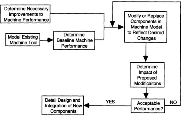
The process for modifying an existing machine is shown in Figure 1.6. First, a kinematic model of the existing machine tool is constructed. Evaluation of this model provides an indication of the current performance of the machine tool, and allows for
Figure 1.6: Process for Modification of Existing Machine Tools
the determination of a "baseline" of the performance of the machine tool. This model is then modified to reflect the changes resulting from the replacement or addition of new components. The new model is evaluated to determine the performance of the modified machine, as well as
the feasibility of including the selected components. If the performance increase is acceptable, the proposed changes proceed to the detailed design phase (which is similar to the detail design phase described above). Unacceptable performance indicates that the selected components will not perform to the required level of performance, or that the integration of these components into the complete machine tool is not correct. By following the above process, the designer can quickly and confidently determine the modifications necessary to gain the desired increase in machine tool performance.
1.4 Existing Software for Precision Machine Design
This section presents an overview of the existing software available for design and analysis of precision machine tools. Three major types of software currently exist: specific Chapter 1: Introduction
applications for the design of machine tools, packages for the simulation of machine tool assemblies and sub-assemblies, and general software developed for non-machine tool specific applications.
1.4.1. Specific Machine Tool Design Applications
Of the existing packages developed specifically for the design of machine tools, all are non-commercial applications developed for research purposes. This section presents an overview of several of these packages:
* Chakrabarti et al. [1992] developed a system for the generation of machine tool concepts through the combination and adaptation of existing elements. The system captures the functionality of existing mechanisms and sub-assemblies and generates new concepts based on combinations and adaptations of these elements. Evaluation of these concepts is the responsibility of the designer.
* Gorti and Sriram [1995] developed a system for the geometric design of a part based on function-symbol and symbol-form mapping. Constraints, standard components, and design process knowledge are combined with geometric primitives to define the shape of the desired part.
* Li et al. [1996] presented a system for the kinematic design of mechanisms based on heuristic and qualitative representations. Devices are represented within the system and selected based on evaluation of the user-input requirements with the functional
descriptions contained within the program.
* Colton and Dascanio [1991] develop the Intelligent Design System (IDS) for the geometric design of parts. The system allows the designer to specify geometry and function based on a library of features. These features contain geometric as well as functional data. Material type, manufacturing process, and other information may also be included in the part representation. Evaluation and verification of the design takes place in separate applications.
* Kannapan and Marshek [1990] propose a system for the modeling machine elements based on first order predicate and algebraic logic. These models are collected into libraries for use in the conceptual stages of design. Libraries may be used by designers Chapter 1: Introduction
or to provide information for design verification, selection, and synthesis systems based on computational routines.
1.4.2. Applications for the Simulation of Machine Tool Assemblies
The simulation of a complete machine or machine sub-assembly requires detailed knowledge of the system in question, and if often reserved for the detailed stage of design. These packages may, however, be used for conceptual evaluation if enough detail is present in the concept description. Simulation may also be used to determine the feasibility of a
sub-assembly or component for use in a complete machine.
* Spur et al. [1990] developed a system for the evaluation of machine tool designs based on a library of machine sub-assemblies and workpieces. The designer begins by
selecting a desired workpiece profile, defining various parameters of the workpiece, and selecting the desired process. A three-dimensional geometric model is then constructed of the machine based on a standard component library, and simulation of the machining process provides details on the operation of the tool. Results are limited to kinematic descriptions of the machining process.
* Mahajerin [1988] presents an application for the simulation of spindle growth due to temperature effects. The spindle is modeled as a solid shaft with two bearings at a given location. The simulation provides information on the expected deflection of the spindle due to temperature rise in the bearings.
* The Machine Tool -Agile Manufacturing Research Institute is in the process of developing the Virtual Machine Tool. This application simulates and evaluates a range of processes executed on alternative topological machine configurations. Error
compensation and vibrations suppression methods are also explored to improve
performance of existing machine tools. The machine to be simulated must be described both kinematically and dynamically.
While the above packages provide a detailed investigation of machine tools or sub-assemblies, these simulations required detailed knowledge of the machine construction and layout. Much of this information is not specified in the conceptual phases of design; as a result, the above simulation packages are generally not practical for conceptual evaluation.
1.5 Research Overview
The purpose of this research is to identify the inadequacies of existing methods for the conceptual design and evaluation of precision machine tools and to develop a set of
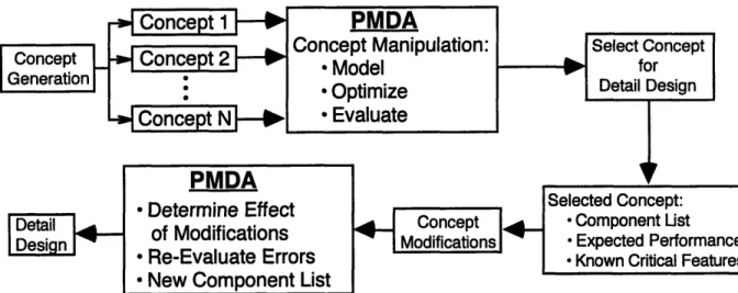
computational tools to address these inadequacies. To address the above needs, the Precision Machine Design Assistant (PMDA) is developed as an integrated software tool for the rapid evaluation of machine tool concepts. Figure 1.7 provides an overview of the goals and
functionality of PMDA, while Figure 1.8 shows how PMDA can be integrated into the machine tool design cycle.
Figure 1.7: Overview of the Precision Machine Design Assistant
Chapter 1: IntroductionThe Precision Machine Design Assistant
Problem:
Tradtional methods for preliminary design of precision machine tools results in: * incomplete and informal evaluation of machine tool concepts
* a lack of understanding of the influences of each component on total tool-workpiece interaction error
* machine tool concepts that are incomplete, inefficient, or impractical Solution:
Develop a computational tool for the rapid evaluation and optimization of precision machine tool concepts
Objectives:
To provide for:
* the rapid evaluation of tool-workpiece interaction errors in precision machine tool concepts
* the determination of the influence of each component on the total machine performance
* the optimization of precision machine tool concepts based on design constraints and standard catalog components
Methods:
* represent precision machine tools as a set of components connected as rigid bodies
* model machine components through standard representations * evaluate machine error through the use of Homogeneous
Transformation Matrices (HTM)
* evaluate other machine performance issues through the use of design constraints
* include both comercially available and custom machine components
The functionality of PMDA is divided into four key areas: kinematic modeling, error evaluation, and constraint specification and evaluation, and concept optimization. A model of the proposed machine concept is created through the use of the error budget methods described above, and is based on a series of catalogs containing representative component parts.
Constraints are set automatically according to the interactions specified between the selected components, or by the designer as necessary. Once the collection of constraints describing the entire machine is developed, the constraints may be evaluated on an individual basis, or the entire constraint "network" may be optimized.
Figure 1.8: PMDA in the Machine Tool Design Cycle
This dissertation is presented in the following manner:
* Chapter 2 presents the principles of machine tool error calculations. Type of error motions and their sources are presented, as are the combinatorial rules employed in error budget formulations. A sample error budget for a simple mechanism is also presented as an example.
* Chapter 3 is an overview of constraint-based design. Mathematical constraints are defined for a variety of relationships, and the sources of constraints are reviewed. The section concludes with an overview of current constraint satisfaction algorithms, and an example constraint network for a simple mechanical assembly.
* Chapter 4 is a description of the component representations used in PMDA. An overview of standard mechanical components used in machine tools is offered, and the data contained in typical component catalogs is presented. The organization and hierarchy of PMDA objects is
presented, as are the different levels and types of computational objects.
* Chapter 5 presents an overview of the functionality of PMDA. The methods for kinematic modeling, error motion modeling and evaluation, and constraint evaluation in PMDA are presented.
* Chapter 6 contains two examples related to the form and functionality of PMDA. The first example provides an overview of the information contained within the rotary bearing objects, and the methods for incorporating variations in components into the object hierarchy. The
second example presents the determination of the total tool-workpiece interaction error for a simple machine spindle, and the evaluation of the constraint network associated with this spindle.
* Chapter 7 covers conclusions and recommendations for future work.
2.0 Principles of Machine Tool Error Calculations
2.1 Introduction
The basic principles governing the use and development of an error budget for machine tool conceptual evaluation was presented in Chapter 1. This chapter presents a more detailed analysis of the construction and use of error budgets. The primary sources of common
machine tool error motions are described, as is a generic method for representing these motions with respect to a machine component. Rules for combining these errors into a comprehensive prediction of tool-workpiece interaction errors is also included. In addition, an example if provided to illustrate the above principles.
2.2 Sources of Machine Tool Errors
Machine tool errors are classified into four major types: geometric, thermal, load-induced, and dynamic. A detailed understanding of these errors, their relative magnitudes, and their sources is critical to the formulation of any machine tool error budget. Failure to correctly account for and estimate any of these errors will result in an inaccurate error budget and a biased evaluation of the machine tool in question. The sources of machine tool errors discussed in this section are:
*
Geometric -due to the deviation of form of the component*
Thermal Errors -deformations due to temperature gradients*
Loading Errors -deformations due to external or internal loads*
Dynamic Errors -due to friction and vibrationThis section presents an overview of the sources of the errors listed above, as well as a summary of the effects of these errors on precision machine tools. Examples of these errors for typical commercially-available components are also provided.
2.2.1 Geometric Errors
Geometric errors are errors associated with the form of a particular component. These include errors due to straightness of linear surfaces, surface finish effects, twist, bow, and
other errors due to imperfections in the manufacture of the component. In the scope of this
dissertation, geometric errors also include some forms of kinematic1 or assembly errors, such as a failure to achieve parallelism and perpindicularity. Other kinematic errors, such as
workpiece mounting or fixturing concerns, are treated as loading errors and are discussed in a later section.
Straightness error is defined as the deviation of a linear feature of a part from an ideal straight line. In a similar fashion, surface finish error is the deviation of the surface profile from an ideal planar profile. The difference in the above definitions is one of scale:
straightness is often identified with macroscopic features, while surface finish is defined in terms of microscopic imperfections. Figure 2.1 illustrates the difference between straightness and surface finish. Straightness will affect the ability of an axis to position a carriage in a consistent manner, resulting in deviations along the bearing surface. Only linear motion
Straightness Error f(x)
Figure 2.1: Surface Finish and Straightness Errors
components will have straightness-induced error motions, since rotary systems are not measured with respect to a straight line reference. Surface finish errors, however, affect all components involving mechanical contact, including rotary and linear bearings, since the mechanical contact between two imperfect surfaces will result in an imperfect motion.
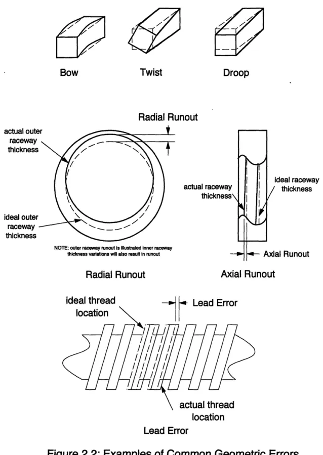
Other geometric errors include "bow", twist, and droop in shafts and beams; radial and axial runout in rotary bearings; and lead errors, bow, and windup in leadscrews. Figure 2.2 provides graphical examples of some of these errors. All of these errors deal with
manufacturing inaccuracies and can be accounted for through a variety of statistical or empirical methods discussed below. Care must be taken not to classify errors caused by loading as geometric errors; loading a leadscrew will result in twist along the longitudinal axis, which will be superimposed on the existing twist resulting from manufacturing inaccuracies. While
1 "kinematic" refers to the mountings and connections of components Chanter 2: Princinles of Machine Tool Error Calculations
Bow
Twist
Radial Runout
actua
NOTE: outer raceway runout is Illustrated inner raceway thickness variations will also result in runout
Radial Runout
ideal raceway thickness
al Runout
Axial Runout
ideal thread
-- ý [• Lead Errorlocation
Lead Error
Figure 2.2: Examples of Common Geometric Errors
Chapter 2: Principles of Machine Tool Error Calculations
actual outE raceway thickness ideal outer raceway thickness
Droop
loading errors will alter the geometry of the part in a similar fashion to manufacturing errors, the root cause of the errors are fundamentally different and must be considered as such.
Geometric errors related to kinematics, also referred to as assembly errors, are errors due to the inaccuracies in the assembly of the machine tool. Unlike other geometric errors, which represent the effect of an individual component on the system, assembly errors represent the errors associated with the joining of multiple components. The major assembly errors dealt with in conceptual evaluation are parallelism and perpindicularity. Parallelism and
perpindicularity errors result in Abbe effects for both linear and rotary motion parts.
Parallelism, as shown in Figure 2.3, is the angular error between two ideally parallel surfaces or lines and the actual surfaces or linear features. Perpindicularity is defined in a similar fashion but deals with perpendicular features. In both cases, the error is defined with respect to a datum surface; this datum surface must be at a known location to other datum surfaces of the machine tool, and the datum should not be altered once set.
actu
Figure 2.3: Parallelism and Perpindicularity Error
Geometric errors may be predicted and accounted for by empirical, statistical or heuristic methods. For custom parts that are familiar to the designer, existing machine tool parts representative of components of a given concept may be accurately measured (by CMM or other method), and the results used to predict average values for the geometric errors. For commercially-available components, tolerance information and the experience of applications engineers may be used to estimate best case, average, and worst case performance of a given component. Statistical methods may also be used to predict the average, best-case, and worst-case for a given type of component. Estimates may also be based on past experience and the Chapter 2: Principles of Machine Tool Error Calculationsperformance of existing machine tools, or on the intuition of the designer. In all cases, the manufacturing errors must be estimated or predicted and included, since no theoretical relationships currently exist for the determination of manufacturing errors.
2.2.2 Thermal Errors
Thermal errors, also classified as thermally-induced geometric errors, are errors in geometry associated with variations in ambient temperature or temperature gradients in, on, or around the machine tool. While the variation in temperature results in changes in component geometry, thermal errors are considered separate from the previously described geometric errors since thermal errors result from variations in environment and not variations in manufacture. Because of this dependency, thermal errors will vary with respect to machine operating condition while geometric errors will remain essentially constant throughout the lifetime of the machine.
All thermal errors are a consequence of the relationship:
AL = a AT Lo
where a is the coefficient of thermal expansion of the material, and AT is the deviation of temperature from the undeflected shape. Several different modes of this equation common to machine tools are shown in Figure 2.4. For a constant AT caused by a change in equilibrium temperature, the result is an increase in the overall size of the part dimensions. Variable values of AT throughout a given component result in a temperature gradient and more complex
behaviors, including bending and location-dependent variations in component size. Thermal gradients are often present in machine tools, resulting in a non-uniform expansion in the components and the machine tool structure itself. Sources of thermal
gradients include heat generated by friction in individual components, variations in ambient temperature, coolant streams, motors, heat generated by cutting processes, and the body heat
of the machine operator. Any time every component of the machine in not in thermal
equilibrium, gradients will be preset, and the effects must be accounted for to accurately predict the performance of the machine tool in question. For the purpose of error budget calculations,
most ambient conditions (including the effects of ventilation systems, lights, the operator, and other "shop floor" factors) can be assumed constant, and only the gradients resulting from the operation of machine components included in the system error budget.
original @T
O final @T,Uniform (positive)
AT
i ksmrl h li;rc IOULI 101 1 11 III I x T = f(x, I I maxNon-Uniform (positive)
AT
Figure 2.4: Example of Uniform and Non-Uniform
Thermal Errors
Inclusion of thermal errors in the machine tool error budget is a complex process. In the conceptual evaluation phase, most thermal errors may be estimated based on experience and existing designs. Simple calculations based on preliminary assumptions (for example, constant AT for a given part or low thermal conductivity between components) may be used, or more detailed analysis may be made through the use of computational methods. Representative rates of heat generation and temperature rise are also generally provided for commercially-available components. If large thermal gradient are expected, or the design is expected to be sensitive to thermal errors, the errors budget should be modified to account for each of these conditions.
2.2.3 Loading Errors
Loading errors include the deflections of each component of the machine (including machine structure) due to gravitational forces, mounting of individual components or the entire machine tool, and cutting forces. In many cases, these deformations are substantial and can be the most significant errors affecting the given machine tool.
Loading errors due to gravity are the result of the static weight of each component (including structural members) deflecting the machine tool structure itself. While the weight of these components (expect the workpiece) are assumed to be constant during conceptual
evaluation, the location of these components will change during the operation of the machine. This will result in different deflections based on different machine "poses" or operating conditions. For this reason, an error budget must be constructed to allow evaluation of machine performance for a variety of operating conditions.
The errors due to the machining process are less straightforward than gravitationally-induced errors. For some machine tools, such as photolithography machines
("wafer-steppers") and waterjet cutters, the forces generated by the machining process (exerted on the cutting tool and supporting structure) are negligible, while the cutting forces generated by metal lathes and machining centers can be substantial. In machine tools where machining forces are expected to be significant, care must be taken to both correctly estimate the magnitude of these forces and determine the distribution of these forces and associated deflections between the structure supporting the tool and the structure supporting the workpiece. Inclusion of these effects in the system error budget may be accomplished by estimates based on past experience, measurements of existing machine tools, simulation of cutting processes, and/or calculations and modeling of the stiffnesses of the structures affected by these forces.
Errors caused by internal forces, such as assembly errors and bearing preload, are often the most neglected type of errors in precision machine tool design. Assembly (or mounting) errors are the result of forces generated by mounting of components to the machine or the machine to the floor. The most common mounting error is forced geometric congruence, where two parts of slightly different geometry are forced into alignment. This forced alignment generates internal stresses in the mated parts, resulting in the distortion of the parts from their ideal shape. For example, a linear bearing rail bolted to a curved base will deform to the shape of the base, and the resulting deflection will lead to errors in the rail, bearing, and attached components. These errors must almost always be estimated based on previous experience or measurement of existing designs. Bearing preload is another source of internal-force induced errors. In this case, a load is applied to a bearing to increase stiffness and fatigue life. This preload also leads to an increase in internal stresses and deflections of the bearing and
surrounding structure. In the case of preload, however, the force applied to the bearing is known, and the resulting deflections may be incorporated into the system error budget.
2.2.4 Dynamic Errors
Dynamic errors refers to any error influencing or resulting from the movement of the machine. These errors are caused primarily by friction in the bearing systems and vibrations in the surrounding structure. In the case of bearing friction, the machine axis in question is unable to servo to the desired position due to high levels of static friction between the bearing Chapter 2: Principles of Machine Tool Error Calculations