HAL Id: tel-02917681
https://tel.archives-ouvertes.fr/tel-02917681
Submitted on 19 Aug 2020HAL is a multi-disciplinary open access archive for the deposit and dissemination of sci-entific research documents, whether they are pub-lished or not. The documents may come from teaching and research institutions in France or abroad, or from public or private research centers.
L’archive ouverte pluridisciplinaire HAL, est destinée au dépôt et à la diffusion de documents scientifiques de niveau recherche, publiés ou non, émanant des établissements d’enseignement et de recherche français ou étrangers, des laboratoires publics ou privés.
mini-invasive, la biopsie et les procédures d’ablation
Chinmay Samant
To cite this version:
Chinmay Samant. Echographie laparoscopique pour la chirurgie mini-invasive, la biopsie et les procé-dures d’ablation. Chirurgie. Université de Strasbourg, 2019. Français. �NNT : 2019STRAD054�. �tel-02917681�
MSII GRADUATESCHOOL: "MATHÉMATIQUES, SCIENCES DE L’INFORMATION ET DE L’INGÉNIEUR"
THESIS
PRESENTED BY CHINMAYSAMANTONDECEMBER16th, 2019
submitted in fulfillment of the requirements for the degree of Doctor of
Philosophy of the University of Strasbourg
Area/Speciality: SIAR-Image & Vision (Robotics)
Ultrasound Laparoscopic Guidance for
Minimally Invasive Surgery, Biopsy, and
Ablation Procedures
THESIS supervised by:Adlane HABED, Assistant Professor MichelDE MATHELIN, Professor
EXTERNAL REPORTERS: David FOFI, Professor Pascal VASSEUR, Professor OTHER MEMBERS OF THE JURY: John KLEPPER, PhD
Acknowledgements
I thank Siemens Healthcare, France for funding this research (under CIFRE ANRT convention with the ICube - University of Strasbourg, CNRS - Laboratory and IHU, Strasbourg) through ARES project. I thank Mr. John Klepper (Research Scientist, Siemens Healthcare) for realising this project and Mr. Ankur Kapoor (Research Engi-neer, Siemens Healthcare Princeton) for his contribution in the development of hard-ware used in this project. I thank Mr. Laurent Goffin for his contributions in devel-oping the software for experimentation. I thank the staff of IHU Strasbourg, in their assistance for using the medical instruments.
I give my sincere thanks to my thesis supervisor, teacher and mentor Mr. Adlane Habed. You showed me how to walk in the world of academics. You supported me in my failures guiding me patiently toward my success. Your passion for achieving ex-cellence in the work is an invaluable treasure for Science and I am fortunate to receive a part of it. Your big heart shielded me in the turbulent times and held me high in the best ones.
I thank my thesis director, Mr. Michel de Mathelin for bringing me in this project. Your decisive and practical advises helped me realise my thesis. With your generous support and encouragement, I could gather the confidence of demonstrating my re-search to the international platforms. Your leadership and professional efficiency will always be an inspiration for me and ICUBE.
I would like to extend my thanks at my colleagues and members ICUBE laboratory. This endeavour was not possible without your support and encouragement. With the dedication for your work, you keep ICUBE on the forefront of technology and I am fortunate to be a part of it.
I made lifelong friends during my PhD. Each and every moment with you will always bring a smile to my face. Thanks for your help at every step; Lijia, Danda-Pani, Sebastian, Imane, Ana, Maximillian, Arda, Devesh, Jérémy and others.
I thank my parents, Aai and Baba. I thank my second parents, uncle Dadakaka and Smita Kaki. Your support and blessings are the eternal source my success. Ana, I can’t thank you enough for everything you did for me. When I was falling apart, your love held me together. And thank you Mamãe and Papai for believing in me all the time.
Contents
Acknowledgements iii
Introduction Générale 1
1 Introduction 7
1.1 Context of the thesis . . . 7
1.2 Scope of the thesis . . . 9
1.3 Contribution of the thesis . . . 10
1.4 Organization of the thesis . . . 11
2 Instrument Registration In Laparoscopic Surgery 13 2.1 History of Laparoscopic Surgery . . . 13
2.2 A Standard Laparoscopic Procedure . . . 16
2.2.1 Advantages and Limitations . . . 18
2.3 Image-guided surgery . . . 19
2.3.1 Imaging . . . 19
2.3.2 Segmentation . . . 20
2.3.3 Tracking . . . 20
2.3.4 Registration . . . 21
2.3.5 Visualization and Interaction . . . 22
2.4 Laparoscope Tracking . . . 24
2.4.1 Optical Tracking System . . . 24
2.4.2 Electromagnetic Tracking . . . 28
2.4.3 Mechanical Tracking . . . 32
2.4.4 Hybrid Tracking . . . 33
2.4.5 Ultrasound Laparoscope Tracking . . . 33
2.5 Summary and discussion. . . 37
3 Laparoscope positioning based on IMU and PSD Camera 39 3.1 Overview of the Ultrasound Laparoscope . . . 39
3.2 Hardware Setup . . . 40
3.2.1 Inertial Measurement Units . . . 41
3.2.2 Position Sensitive Detectors . . . 43
3.2.3 Triangulation using PSDs . . . 45
3.3 New Laparoscope Design . . . 45
3.3.2 Ultrasound Image to Laparoscope Tip Calibration . . . 51
3.4 Sensor Noise Reduction . . . 53
3.5 Summary . . . 54
4 Rotation Averaging and Hand-Eye Calibration 55 4.1 Rotation Averaging . . . 55
4.1.1 Distance Metrics . . . 57
4.1.2 Global Closed-Form Solution for Single Rotation Averaging . . . 58
4.2 Hand Eye Calibration. . . 60
4.2.1 Introduction to Hand-Eye Calibration . . . 61
4.2.2 State-of-the-Art of Hand-Eye Calibration . . . 63
4.2.3 State-of-Art of Robot-World Calibration . . . 69
4.3 Summary . . . 69
5 Robust Hand-Eye Calibration Method 71 5.1 Background and Notations . . . 73
5.1.1 Semi-Definite Programming. . . 73
5.1.2 Rank-Constrained LMI Feasibility Problem . . . 74
5.1.3 Convex-Hull of Rotations . . . 74
5.2 Deterministic Robust Hand-Eye Calibration . . . 75
5.2.1 Semi-Definite Problem Formulation . . . 75
5.2.2 Robust Hand-Eye Calibration . . . 77
5.3 Experiments and results . . . 78
5.3.1 Synthetic Data Experiments . . . 79
5.3.2 Real Data Experiments with Robot-Camera Setup . . . 84
5.3.3 Real Data Experiments with EM-Camera Setup . . . 86
5.3.4 Additional Experiments with RANSAC . . . 88
5.4 Summary . . . 92
6 Conclusion 93
List of Figures
2.1 Bozzini’s Lichtleiter. (Image from www.facs.org) . . . 14
2.2 Left: Internal schematic of endoscope of Antonin Jean Desormeaux by
Pierre Lackerbauer showing the mirror system to reflect light. Right: The usage of the endoscope. . . 15
2.3 Nitze’s Telescopic Laparoscope instruments. (Images from Nitze-Leiter
Museum of Endoscopy) . . . 15
2.4 Left: A Panelectroscope from 1907. Right: Patient undergoing a
gas-troscopy. (Images from Nitze-Leiter Museum of Endoscopy) . . . 16
2.5 Left: Overview of a laparoscopic surgery scene (Image from www.columbiasurgery.org).
Right: Inside the patient’s body during a laparoscopic surgery. (Image from www.longislandsurgery.org) . . . 17
2.6 Left: C-arm imaging machine (Image from www.kiranxray.com). Right:
C-arm machine during a surgery (Image from www.siemens-healthineers.com) 18
2.7 Left: A view of the surgical room from technicians area. Right:
Sur-geon’s communication with the technician. . . 22
2.8 A: Possible path of needle insertion. Part of the pre-planning. B: The
path chosen before the needle insertion. C and D: Real-time progress of needle insertion.(Images from [Tyn+15]) . . . 23
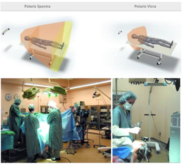
2.9 Top: Polaris products with the schematic of functioning area. Bottom:
Placement of Polaris camera in a surgical room (Images from www.ndigital.com) 26
2.10 Mounting of LED markers on a needle tool (Images from www.vanderbilt.edu) 27
2.11 Optotrack 1D tracking system. Markers for the system shown in top
right. (Images from publish.illinois.edu and www.ndigital.com) . . . 28
2.12 Schematic of electromagnetic tracking system. (Image from www.ndigital.com) 29
2.13 Left: Sensors from Northern Digital. Right: Sensors from Ascension Technology (Image from [Rei13]) . . . 30
2.14 Active electromagnetic field of an electromagnetic transmitter in which
the sensor can be detected. (Image from www.ndigital.com) . . . 30
2.15 Different shapes of the EM transmitters. Table top transmitter lies on the surgical table while the box transmitter is usually mounted alongside the surgical table (Image from www.ndigital.com) . . . 31
2.16 Left: Ferromagnetic material disturbance to the EM tracking field. Right: Eddy current induction effect in the metallic object in the EM field (Im-age from www.ndigital.com) . . . 32
2.17 Overview of the endoscope image based optical tracking system (Image
from [Ogu+14]) . . . 34
2.18 Ultrasound image overlay on the endoscope optical image (Image from [Ogu+14]) . . . 35
2.19 Electromagnetic sensors and camera based hybrid tracking system for US laparoscopes (Image from [Feu+07]) . . . 36
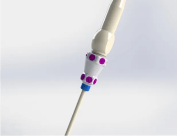
3.1 A standard design of an ultrasound laparoscope without any sensors mounted . . . 39
3.2 Schematic of the US laparoscope tracking setup. . . 41
3.3 Outputs of an IMU sensor system. . . 42
3.4 Design of PSD using a PIN diode. (Image from Georg Wiora). . . 43
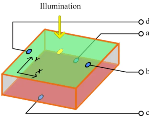
3.5 Position response of a 2D PSD sensor. (Image from [CS10]) . . . 44
3.6 PSD camera pointing at the LED ring mounted on a US probe handle. (Image from Siemens Healthcare) . . . 46
3.7 Ideal position for mounting the PSD camera rig . . . 46
3.8 Design of the LED ring assembly mounted on the laparoscope handle . 47 3.9 Schematic of the laparoscope handle and the PSD camera . . . 47
3.10 Schematic of the laparoscope . . . 49
3.11 Schematic of the laparoscope tip . . . 50
3.12 Schematic of modified wire phantom for ultrasound probe calibration. The IR-LED Grid is detected by the PSD sensors to provide the trans-formation of the wire phantom . . . 51
3.13 Schematic of the wire phantom for ultrasound probe calibration . . . 52
4.1 Hand-Eye calibration setup with a robot hand manipulator and a camera. 61 5.1 Traditional Hand-Eye setup in robotics with a camera mounted on a robot gripper attached to the robot base. Transformations are obtained via the kinematic link and camera pose estimation.. . . 72
5.2 Gaussian noise on hand and camera motions. RMS of quaternion rota-tion errors (left), RMS of relative translarota-tion vector errors (right). . . 80
5.3 Uniform noise on hand and camera motions. RMS of quaternion rota-tion errors (left), RMS of relative translarota-tion vector errors (right). . . 80
5.4 Outliers replacing increasing percentage of motions. RMS of quaternion rotation errors (left), RMS of relative translation vector errors (right). . . 81
5.5 Increasing number of motions. RMS of quaternion rotation norm (left), RMS of relative translation vector norm (right). . . 82
5.6 Outliers replacing increasing percentage of motions. RMS of quaternion rotation norm (left), RMS of relative translation vector norm (right). . . . 83
5.7 Average time performance of each iteration. Left Y-axis: Average time taken by each iteration in 50 trials. Right Y-axis: Total number of itera-tions. . . 83
5.8 Average time performance while changing the regularization parame-ter. Left Y-axis: Average time taken by each iteration in 50 trials. Right Y-axis: Total number of iterations.. . . 84
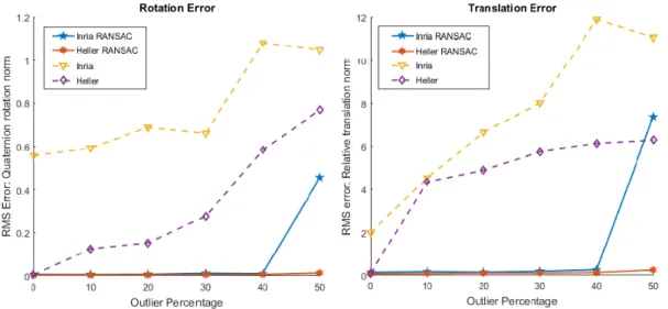
5.9 Real data from robot hand. Comparison against ransac method [Fur+18]
using 30 pre-selected motions.. . . 85
5.10 Real data from robot hand. A certain percentage of time-shifted outliers are added to replace good motions from the 30 pre-filtered motions.. . . 86
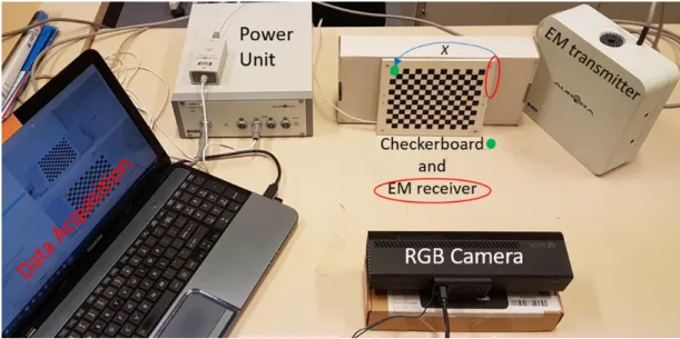
5.11 Our camera-EM data acquisition setup. The camera and EM transmitter remain fixed. With each motion, the checkerboard pattern moves in front of camera along with the attached EM receiver.. . . 87
5.12 Schematic of EM sensor - camera setup to demonstrate Hand-Eye cali-bration. Contrary to the original Hand-Eye calibration setup, the cam-era is fixed and the calibration pattern moves: the chain of transforma-tion remains equivalent. . . 87
5.13 Dataset from EM-sensor setup. The graphs show the distribution of the pixel errors. In the box plot, the red central line indicates the median pixel error. The top and bottom blue lines of the box indicate 75th and 25th percentile respectively. The whiskers extend to the most extreme data points. . . 89
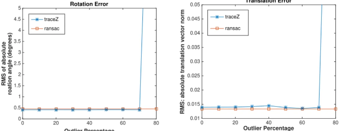
5.14 On the Y-axis, an increasing percentage of outliers is replacing the mo-tions. Left: RMS of quaternion rotation errors. Right: RMS of relative translation vector errors. . . 91
Introduction Générale
Contexte de la thèse
Ce projet est réalisé sous la convention CIFRE-ANRT. Il est financé par Siemens Health-care (France) en collaboration avec ICube (CNRS), l’IHU et l’Université de Strasbourg à travers le projet ARES. L’objectif de ce projet collaboratif est de développer des tech-nologies liées à la chirurgie mini-invasive et ses instruments.
De nos jours, la chirurgie laparoscopique minimalement invasive guidée par l’ima-ge est de plus en plus pratiquée pour le diagnostic et l’intervention. Par rapport à la chirurgie ouverte, une telle procédure ne nécessite que de petites incisions corporelles et conduit à une récupération plus rapide du patient ainsi qu’à un traumatisme post-chirurgical réduit. Dans ce type de chirurgie, le chirurgien s’appuie sur un flux vidéo plutôt que sur un accès visuel direct aux organes. Ceci, combiné avec les progrès tech-nologiques dans les instruments laparoscopiques chirurgicaux et l’imagerie médicale, a conduit les chirurgiens à effectuer la chirurgie de nouvelles façons qui sont uniques à la chirurgie laparoscopique, entraînant, dans certains cas, des procédures plus rapi-des que celles effectuées dans une chirurgie ouverte et un impact réduit sur l’état de santé du patient.
Bien que la chirurgie laparoscopique devient de plus en plus pratiquée en rai-son de ses avantages pour les patients, en général, les chirurgiens ont tendance à avoir plus confiance en la chirurgie ouverte. Cela est dû en partie au champ de vi-sion limité, à l’espace confiné dans lequel ils doivent opérer, à la difficile coordina-tion œil-main et au niveau élevé de dextérité manuelle requis en chirurgie laparo-scopique. Les chirurgiens peuvent choisir le type de procédure en fonction de leur évaluation des risques. Par exemple, en chirurgie de re-sectionnement du foie, hipa-tectomie, le chirurgien doit choisir entre une intervention chirurgicale laparoscopique ou une chirurgie ouverte en fonction de la complexité de l’opération. Si les scans pré-chirurgicaux montrent que la propagation de la maladie dans le foie est isolée, la procédure chirurgicale est plus simple et le chirurgien pourrait tout aussi bien utiliser la laparoscopie. Si la maladie est répandue, le chirurgien préférerait une chirurgie ouverte car elle permet de vérifier soigneusement toute la zone et d’éliminer com-plètement la maladie. La préférence pour la chirurgie ouverte, dans un tel cas, est due au manque de confiance du chirurgien dans les instruments laparoscopiques et l’imagerie.
l’anatomie du patient affichée sur un écran. En raison du manque de rétroaction hap-tique, qui est disponible pour le chirurgien dans une chirurgie ouverte, les chirurgiens s’appuient sur des modalités d’imagerie, telles que les images échographiques (US), en plus de la vue 2D traditionnelle de la caméra du laparoscope sur l’écran. À l’aide de la TDM / IRM préopératoire, des images produites par des appareils de radiologie à arceau et des images laparoscopiques échographiques, les chirurgiens peuvent voir au-delà de la surface des organes avant de les sectionner. Par exemple, dans l’exemple de l’hipatectomie discuté ci-dessus, les chirurgiens s’appuient sur les images médi-cales pour planifier le chemin de l’incision. Les images préopératoires ainsi que les images peropératoires en direct fournissent des informations visuelles sur l’anatomie du foie, afin que les chirurgiens puissent éviter les vaisseaux majeurs lors de l’ablation de la maladie du foie. Au fur et à mesure que les techniques chirurgicales s’améliorent, la fiabilité et la confiance dans les techniques d’imagerie augmentent. De nombreuses nouvelles techniques de fusion d’images multimodales et de suivi d’instruments la-paroscopiques ont été développées pour aider le chirurgien. En conséquence, une vue meilleure, plus complète et plus immersive de la scène chirurgicale augmente la confiance du chirurgien dans les instruments laparoscopiques.
La chirurgie guidée par l’image moderne vise à fournir une vue complète de l’o-pération au chirurgien. Cette vue peut utiliser différentes modalités d’image fusion-nées pour présenter des informations supplémentaires superposées sur la vidéo de la caméra du laparoscope. Par exemple, des images de tomodensitométrie pré-acquises peuvent être superposées sur l’image de la caméra. Les tranches du volume d’image CT-scan sont sélectionnées en temps réel, correspondant aux images de caméra corre-spondantes du laparoscope. Les étapes de cette technique sont les suivantes:
• Imagerie: les images sont acquises à partir de différents instruments d’imagerie tels que la tomodensitométrie, l’IRM, l’échographie ainsi que la caméra en temps réel avant et pendant la chirurgie.
• Segmentation: la zone de l’opération, telle que la forme de l’organe, doit être séparée du fond des images. Ce processus est appelé segmentation.
• Tracking: il s’agit d’acquérir la pose des instruments laparoscopiques en temps réel par rapport aux objets segmentés de la scène. La pose est acquise à l’aide de capteurs montés sur les instruments.
• Enregistrement: dans cette étape, différentes modalités d’image sont mises en correspondance en identifiant et en faisant correspondre des repères communs. Ce processus peut être très gourmand en ressources CPU dans les applications en temps réel.
• Visualisation et interaction: souvent une partie négligée de l’ensemble du pro-cessus, la visualisation des images à l’écran ainsi que l’interaction des chirurgiens avec les instruments et les commandes du système informatique définissent l’u-tilisabilité, par les chirurgiens, de la technique de guidage.
La machine Siemens S3000, une prouesse technologique pour l’imagerie ultra-sonore, intègre la plupart des étapes ci-dessus. Sa technologie logicielle eSieFusion peut effectuer le suivi des sondes à ultrasons pour l’enregistrement des images écho-graphiques en temps réel avec les images de volume de scan CT / IRM préopératoire. La sonde à ultrasons externe est suivie à l’aide de systèmes de capteurs électromag-nétiques (EM) tels que NDI Aurora et les informations de pose de ce système sont utilisées pour le récalage. Étant donné que le capteur EM est monté sur la sonde à ultrasons externe, le capteur reste à proximité de l’émetteur EM qui est requis pour le suivi EM. Cependant, dans le cas d’un laparoscope à ultrasons, qui a un réseau d’échographes similaire monté sur sa pointe, le suivi EM traditionnel échoue car la pointe du laparoscope qui doit être suivie pénètre profondément dans le corps. Si le capteur EM est monté sur la pointe, il est soumis à du bruit: des distances plus longues de l’émetteur EM entraînent des erreurs de suivi plus importantes. Dans cette thèse, nous travaillons dans le cadre du suivi des laparoscopes à ultrasons avec le système Siemens eSieFusion. L’objectif est de surmonter les inconvénients du système de suivi EM pour permettre le suivi de la pointe du laparoscope à ultrasons fonctionnant pro-fondément dans le corps du patient.
Portée de la thèse
Dans cette thèse, nous visons à proposer des solutions pour améliorer l’usabilité d’un laparoscope à ultrasons en trouvant sa pose (position et orientation) en temps réel. Cette amélioration serait utilisée pour fournir au chirurgien une information visuelle complète sur l’emplacement de la pointe du laparoscope autour des organes.
Le suivi du laparoscope fait partie d’un pipeline de réalité augmentée dans lequel le chirurgien peut avoir une vue 3D de la procédure chirurgicale sur l’écran. L’objectif est de montrer à l’équipe chirurgicale une image en temps réel du mouvement du laparoscope autour de l’image 3D de l’anatomie du patient. Parmi les nombreuses étapes impliquées dans ce processus, le suivi peut être une limitation pour l’ensemble de la procédure en raison de sa dépendance à l’égard des systèmes de capteurs pour fournir une pose détaillée de l’outil. En suivi, plusieurs capteurs (EM, optiques) sont attachés au laparoscope. En utilisant les informations de ces capteurs, le laparoscope est suivi par rapport à un système de coordonnées de référence. Étant donné que les capteurs sont constamment affectés par l’environnement externe tout en fournissant des données en temps réel, il est difficile d’obtenir une pose en temps réel.
Dans cette thèse, nous abordons les défis du suivi des outils en améliorant le pro-cessus d’étalonnage des outils fixes et en proposant un nouveau système de suivi des laparoscopes basé sur des capteurs. Bien que notre objectif soit de suivre la pose d’un laparoscope à ultrasons, la technologie peut être utilisée pour différents instruments laparoscopiques. Par conséquent, nous présentons un aperçu du suivi laparoscopique dans le contexte de la chirurgie guidée par l’image. Tout en présentant les solutions
existantes pour le suivi laparoscopique, nous analysons leurs inconvénients et y remé-dions en proposant notre système de capteurs pour le suivi laparoscopique. Dans le système de suivi proposé, nous avons trouvé deux parties principales du flux de tra-vail essentielles à l’estimation de la pose: le moyennage des données des capteurs et l’étalonnage du corps fixe. Le moyennage des données des capteurs est essentiel pour combiner les données de rotation produisant une valeur unifiée de la composante ro-tationnelle de la transformation de pose finale. Dans cette thèse, nous présentons différentes méthodes pour résoudre le problème. En outre, l’étalonnage du corps fixe, également connu comme Hand-Eye calibration, fournit une transformation fixe entre deux capteurs de pose connectés rigidement à un corps immobile. Notez que, dans toutes les solutions de suivi des laparoscopes à ultrasons existantes, les capteurs de pose sont fixés de manière rigide au corps des instruments laparoscopiques et, par conséquent, le problème de l’étalonnage œil-main se pose. Nous fournissons un his-torique détaillé de ce problème ainsi que des solutions de pointe. Nous présentons également une nouvelle méthode d’étalonnage main-œil qui est robuste au bruit et aux valeurs aberrantes. Nous testons cette méthode de manière exhaustive par rap-port aux méthodes existantes et présentons les résultats en utilisant différents types de données.
Contribution de la thèse
La première contribution de cette thèse est dans le processus d’étalonnage des out-ils. Les systèmes de suivi optique et EM ont des limitations physiques qui réduisent leurs performances. Par exemple, les systèmes optiques doivent maintenir un champ de vision dégagé et ne peuvent donc pas être utilisés pour suivre la pointe des outils laparoscopiques, car ceux-ci fonctionnent à l’intérieur du corps du patient où la ligne de visée entre le marqueur optique et la caméra ne peut pas être maintenue. Les cap-teurs de suivi EM sont flexibles et de très petite taille. En conséquence, ils peuvent être utilisés pour suivre la pointe du laparoscope mais peuvent être constamment affectés par des perturbations électromagnétiques. Leurs performances se dégradent égale-ment rapideégale-ment à mesure que la distance entre l’émetteur EM et le capteur récepteur augmente. Pour compenser les inconvénients de ces deux systèmes, des technologies de capteurs hybrides ont été développées. Ces technologies utilisent conjointement le suivi optique et EM. Un bloc fondamental de ce système est l’étalonnage du système dans lequel un étalonnage fixe entre les capteurs montés sur le laparoscope est obtenu. En robotique, cet étalonnage fixe est appelé «étalonnage main-œil».
Dans cette thèse, nous proposons une nouvelle formulation du problème d’étalon-nage main-œil. Notre formulation repose sur la contrainte de la rotation recherchée pour appartenir à ce que l’on appelle l’enveloppe convexe des rotations. Sur la base de cette formulation, nous avons conçu un algorithme robuste déterministe pour ré-soudre le problème d’étalonnage main-œil. Notre algorithme est robuste aux valeurs
aberrantes ainsi qu’au bruit dans les données obtenues à partir des capteurs de pose. En particulier,
• nous proposons une relaxation du problème d’étalonnage main-œil qui peut être résolu en utilisant de la programmation semi-définie, pour laquelle une fonc-tion convexe des matrices de rotafonc-tion est requise. Nous utilisons le concept d’enveloppe convexe des matrices de rotation pour formuler notre problème sous sa forme convexe;
• afin d’assurer l’appartenance de la solution à l’ensemble des rotations, nous re-formulons le problème relaxé en un algorithme d’itération convexe de contrainte de rang. Bien que le problème ne soit pas convexe à ce stade, notre formula-tion permet d’utiliser un schéma d’optimisaformula-tion alterné pour converger systé-matiquement dans la pratique vers la solution recherchée;
• afin de filtrer le bruit élevé des capteurs et les valeurs aberrantes, nous pro-posons une approche de repondération itérative performante. Avec cet algo-rithme, nous résolvons systématiquement le problème d’étalonnage main-œil même en présence de niveaux élevés de bruit et de données aberrantes.
La méthode complète est publiée dans la conférence IROS 2019 [Sam+19] y étant ac-ceptée pour une présentation orale. De brefs résultats de cette méthode sont présentés dans CNIV 2019 [SHM19a].
Parallèlement à notre méthode robuste pour l’étalonnage main-œil, nous présen-tons également une approche conventionnelle utilisant RANSAC (Random Sample Con-sensus) pour filtrer les valeurs aberrantes. Nous présentons un cadre RANSAC basé sur un seuillage «géométrique» dans lequel tout algorithme d’étalonnage main-œil peut être utilisé. Nous avons présenté cet algorithme ainsi que les résultats expéri-mentaux dans l’édition 2019 de la conférence CRAS-SPIGC [SHM19b].
Une autre contribution de cette thèse est un nouveau système de suivi pour les laparoscopes à ultrasons. Un laparoscope à ultrasons se compose d’un ensemble d’émetteurs d’ultrasons à l’extrémité mobile du laparoscope. Cet équipement four-nit une image en temps réel au-delà de la surface des organes, aidant le chirurgien à planifier et à suivre la chirurgie avant de pratiquer une incision. En raison de la nature même de l’image échographique, l’estimation de la pose d’un laparoscope à ultrasons via cette image est un défi. Si la pointe du laparoscope est hors du champ de vision de l’endoscope vidéo qui l’accompagne, le chirurgien peut trouver les images échographiques désorientantes. La technologie de suivi EM peut aider cette situation si un capteur EM est attaché à la pointe du laparoscope, mais la précision du suivi EM est grandement affectée lorsque le laparoscope est à l’intérieur du corps du patient. Nous proposons une nouvelle solution à ce défi en utilisant des capteurs optiques et des centrales inertielles (IMU). Les IMU sont des capteurs électroniques autonomes qui peuvent fournir des informations de rotation fiables. Nous proposons d’utiliser une série d’IMU montés sur le corps et la pointe du laparoscope qui sont accom-pagnés d’un suivi optique. Le suivi optique fournit les informations de position et
d’orientation de la poignée du laparoscope. Combinés ensemble, les IMU et le suivi optique peuvent fournir une pose à 6 degrés de liberté (DOF). Les avantages de ce système de suivi sont qu’il n’est pas limité par la portée comme le système de suivi EM et n’est limité que par la contrainte de ligne de visée du système de suivi optique.
Organisation de la thèse
Le deuxième chapitre de la thèse présente une brève histoire de la chirurgie laparo-scopique et des outils. Il décrit également une procédure générale en chirurgie la-paroscopique pour fournir un contexte à l’application de la thèse. Il présente ensuite brièvement les étapes d’une chirurgie guidée par l’image. Ensuite, nous présentons un aperçu complet des technologies de suivi des laparoscopes ainsi qu’une description de deux technologies de suivi hybrides. Au final, nous présentons une construction générale des laparoscopes à ultrasons ainsi que notre proposition pour le suivi hybride optique-IMU.
Le troisième chapitre de cette thèse présente la conception proposée du système de suivi hybride basé sur un capteur optique-IMU pour le laparoscope à ultrasons. Tout d’abord, les composants de configuration matérielle du laparoscope sont expliqués en détail. Ensuite, nous présentons la chaîne cinématique et l’étalonnage du laparo-scope. Enfin, nous présentons les sources d’erreurs possibles et la solution à celles-ci en utilisant le moyennage des rotations.
Le quatrième chapitre de cette thèse présente l’état de l’art du moyennage des rota-tions et de l’étalonnage main-œil. Puisque nous utilisons plusieurs IMU sur le laparo-scope le long du même axe, ils fournissent les mêmes informations de rotation. Nous utilisons cette redondance pour améliorer l’estimation de la rotation en utilisant des algorithmes de moyennage des rotations. L’étalonnage main-œil est un sous-domaine du moyennage des rotations. L’état de l’art sur l’étalonnage main-œil dans ce chapitre sert de précurseur au chapitre suivant.
Le cinquième chapitre de cette thèse présente notre robuste méthode d’étalonnage main-œil. Dans ce chapitre, le problème d’étalonnage main-œil est réintroduit du point de vue de la robotique. Nous présentons également un bref historique de la programmation semi-définie, de la programmation semi-définie à contrainte de rang ainsi que de l’enveloppe convexe de rotations. Notre méthode est présentée avec l’algorithme proposé. Enfin, des essais sur des configurations synthétiques et dif-férentes configurations de données réelles sont présentés avec les résultats de tests approfondis de cette méthode sur plusieurs critères.
Le sixième et dernier chapitre conclut cette thèse. Il réitère également les apports de cette thèse et leur importance dans ce projet. Au final, nous présentons les travaux restants qui n’ont pas été réalisés pendant la durée du projet. Dernièrement, nous indiquons l’impact positif du laparoscope à ultrasons sur l’imagerie médicale et, en général, sur la chirurgie une fois les futurs travaux réalisés.
Chapter 1
Introduction
1.1
Context of the thesis
This project is realised under CIFRE-ANRT convention. It is funded by Siemens Health-care (France) in collaboration with ICube (CNRS), IHU and University of Strasbourg through ARES project. The goal of this collaborative project is to develop technologies related to minimally invasive surgery and its instruments.
Nowadays, minimally invasive image-guided laparoscopic surgery is increasingly performed for diagnosis and intervention. In comparison to open surgery, such proce-dure requires only small body incisions and leads to a faster recovery of the patient as well as a reduced post-surgical trauma. In this type of surgery, the surgeon relies on a video stream rather than a direct visual access to the organs. This, combined with the technological advances in the surgical laparoscopic instruments and medical imaging, has led the surgeons to perform surgery in new ways that are unique to laparoscopic surgery, resulting, in some instances, in faster procedures than those performed in an open surgery and a reduced impact on patient’s health.
Although laparoscopic surgery is gaining ground because of its benefits to the pa-tients, in general, surgeons tend to have more confidence in open surgery. This is partly due to the limited field of view, to the confined space they ought to operate in, to the difficult hand-eye coordination, and to the high level of manual dexterity re-quired in laparoscopic surgery. Surgeons may choose the type of procedure based on their risk assessment of its success. For example, in liver re-sectioning surgery, Hipa-tectomy, the surgeon has to choose between laparoscopic surgical procedure or open surgery depending upon the complexity of the operation. If the pre-surgical scans show that the spread of the disease in liver is isolated then the surgical re-sectioning is simpler and the surgeon might as well use laparoscopy. If the disease is wide-spread, then the surgeon would prefer open surgery as it allows one to thoroughly check the entire area and remove the disease completely. The preference to open surgery, in such a case, is due to the surgeon’s lack of confidence in the laparoscopic instruments and imaging.
In a typical laparoscopic surgery, the surgeon is limited to a 2D view of the patient’s anatomy displayed on a screen. Due to the lack of haptic feedback, which is available
to the surgeon in an open surgery, surgeons rely on imaging modalities, such as ul-trasound (US) images, in addition to the traditional 2D view from the laparoscope’s camera on the screen. With the help of pre-surgical CT/MRI scan, intra-operative C-arm images and ultrasound laparoscopic images, surgeons can see beyond the surface of the organs before intersecting them. For instance, in the Hipatectomy example dis-cussed above, the surgeons rely on the medical images to plan the path of incision. The pre-operative as well as live intra-operative images provide visual information of the anatomy of the liver, so the surgeons can avoid the important arteries during the removal of the disease from the liver. As minimally surgical techniques are improv-ing, the reliance and confidence on the imaging techniques is growing. Many new techniques of multimodality image fusion and laparoscopic instrument tracking have been developed to aid the surgeon. As a result, a better, more comprehensive and im-mersing view of the surgical scene increases the surgeon’s confidence in Laparoscopic instruments.
Modern image guided surgery aims to provide a comprehensive view of the oper-ation to the surgeon. This view may use different modalities fused together to present additional information overlayed on the video from the laparoscope’s camera. For example, images from pre-acquired CT-scans can be overlayed on the camera image. The slices of the CT-scan image volume are selected in real-time, matching the corre-sponding camera images from the laparoscope. The steps involved in this technique are as follows:
• Imaging: images are acquired from different imaging instruments such as CT-scan, MRI-CT-scan, ultrasound as well as camera in real-time during the surgery and also before the surgery.
• Segmentation: the area of the operation, such as the shape of organ, needs to be separated from the background of the images. This process is known as segmen-tation.
• Tracking: it involves acquiring the pose of the laparoscopic instruments in real-time with respect to the segmented objects in the scene. The pose is acquired using sensors that are mounted on the instruments.
• Registration: in this step, different image modalities are matched together by identifying and matching common landmarks in them. This process can be very CPU-resource intensive in real-time applications.
• Visualization and interaction: often an overlooked part of the entire process, the visualization of the images on the screen as well as surgeons interaction with the instruments and the controls of the computer system define the usability of the image guidance technique by the surgeons.
Siemens S3000 machine, a technological prowess for ultrasound imaging, incorpo-rates most of the steps above. Its eSieFusion software technology can perform track-ing of ultrasound probes for registration of real-time ultrasound images with the pre-operative CT/MRI scan volume images. The external ultrasound probe is tracked using electromagnetic (EM) sensor systems such as NDI Aurora and the pose infor-mation from this system is used for registration. Since the EM sensor is mounted on the external ultrasound probe, the sensor remains within the vicinity of the EM trans-mitter unit that is required for EM tracking. However, in the case of an ultrasound laparoscope, which has a similar ultrasound array mounted on its tip, the traditional EM tracking fails as the tip of the laparoscope that needs to be tracked goes deep inside the body. Should the EM sensor be mounted on the tip, it is subjected to noise: longer distances from the EM transmitter lead to larger tracking errors. In this thesis, we work in the context of ultrasound laparoscope tracking with the Siemens eSieFusion system. The goal is to overcome the drawbacks of the EM tracking system to allow the tracking of the US laparoscope tip functioning deep in the body of the patient.
1.2
Scope of the thesis
In this thesis, we aim to propose solutions for improving the usability of an ultrasound laparoscope by finding its pose (position and orientation) in real-time. This improve-ment would be used to provide a comprehensive visual information to the surgeon about the location of the laparoscope’s tip around the organs.
Laparoscope tracking is a part of an augmented-reality pipeline in which the sur-geon can see a 3D view of the surgical procedure on the screen. The goal is to show the surgical team a real-time picture of the movement of the laparoscope around the 3D image of the anatomy of the patient. Amongst the many steps involved in this process, tracking can be a bottleneck to the entire procedure due to its reliance on sen-sor systems to provide a detailed pose of the tool. In tracking, several sensen-sors (EM, optical) are attached to the laparoscope. By using the information from these sensors, the laparoscope is tracked with respect to some reference coordinate system. Since the sensors are affected by the external environment constantly while providing real-time data, there are many challenges in obtaining a real-time pose.
In this thesis, we address the challenges in tool tracking by improving the fixed tool calibration process as well as proposing a new sensor-based laparoscope tracking sys-tem. Though our aim is to track the pose of an ultrasound laparoscope, the technology can be used for different laparoscopic instruments. Hence, we present an overview of laparoscopic tracking in the context of image-guided surgery. While presenting the existing solutions for laparoscopic tracking, we analyse their drawbacks and address them by proposing our sensor system for laparoscopic tracking. In the proposed track-ing system, we found two main parts of the workflow critical to the pose estimation: sensor data averaging and fixed-body calibration. Sensor data averaging is essential to combine the rotation data to produce a unified value of the rotational component of
the final pose transformation. In this thesis, we overview different methods to solve the problem. Furthermore, fixed body calibration, also known as Hand-Eye calibra-tion, provides a fixed transformation between two pose sensors connected rigidly to a non-moving body. Note that, in all existing ultrasound laparoscope tracking solu-tions, the pose sensors are rigidly attached to the body of the laparoscopic instruments and hence the problem of Hand-Eye Calibration arises. We provide a detailed back-ground on this problem as well as the state-of-the-art solutions. We also present a novel Hand-Eye calibration method which is robust to noise and outliers. We test this method comprehensively against existing methods and present the results using different types of data.
1.3
Contribution of the thesis
The first contribution of this thesis is in the tool calibration process. Both optical and EM tracking systems have some physical limitations reducing their performance. For example, optical systems need to maintain a clear line of sight and hence cannot be used to track the tip of the laparoscopic tools since these operate inside the patient’s body where the line of sight between the optical marker and the camera cannot be maintained. EM tracking sensors are flexible and very small in size. As a result, they can be used to track the laparoscope tip but may constantly be affected by electromag-netic disturbances. Their performance also degrades rapidly as the distance between the EM transmitter and the receiver sensor increases. To compensate the drawbacks of these two systems, hybrid sensor technologies have been developed. These technolo-gies use optical and EM tracking together. A fundamental block in this system is the calibration of the system in which fixed calibration between the sensors mounted on the laparoscope is obtained. In robotics, this fixed calibration is known as ’Hand-Eye calibration’.
In this thesis, we propose a novel formulation of the Hand-Eye calibration prob-lem. Our formulation relies on constraining the sought rotation to belong to the so-called convex-hull of rotations. Based on this formulation, we devised a deterministic robust algorithm to solve the Hand-Eye calibration problem. Our algorithm is robust to outliers as well as to noise in the data obtained from the pose sensors. In particular, • we propose a relaxed version of the Hand-Eye calibration problem that can be solved using semi-definite programming, for which a convex function of rota-tion matrices is required. We use the concept of convex hull of rotarota-tion matrices to formulate our problem in its convex form;
• in order to ensure the solution’s membership to the set of rotations, we re-formulate the relaxed problem into a rank-constraint convex iteration algorithm. Although the problem is non-convex at this stage, our formulation allows to use an alter-nating optimization scheme to consistently converge in practice to the sought solution;
• in order to filter out high sensor noise and outliers, we propose an efficient it-erative re-weighting approach. With this algorithm, we consistently solve the Hand-Eye calibration problem even in the presence of high levels of noise and outlier data.
The full method is published in IROS 2019 conference [Sam+19] in which it has been accepted to oral presentation. Brief results of this method are presented in CNIV 2019 [SHM19a].
Alongside our robust method for Hand-Eye calibration, we also present a conven-tional approach using RANSAC (Random Sample Consensus) to filter out outliers. We present a RANSAC framework based on ’geometric’ thresholding in which any Hand-Eye calibration algorithm can be used. We presented this algorithm along with the experimental results in the 2019 edition of CRAS-SPIGC conference [SHM19b].
Another contribution of this thesis is a new tracking system for ultrasound laparo-scopes. An ultrasound laparoscope consists of an ultrasound array at the moving tip of the laparoscope. The ultrasound modality provides a real-time image beyond the surface of the organs helping the surgeon to plan and follow the surgery before mak-ing an incision. Due to the nature of ultrasound image itself, estimatmak-ing the pose of ultrasound laparoscope via this image is a challenge. If the laparoscope tip is out of the view of the accompanying video endoscope, the surgeon can find the ultrasound images disorienting. EM tracking technology can help this situation by attaching an EM sensor to the tip of the laparoscope but the accuracy of the EM tracking is greatly affected when the laparoscope is inside the patient’s body. We propose a new solution to this challenge by using optical and Inertial Measurement Unit (IMU) based sensors. IMUs are self-contained electronic sensors that can provide reliable rotation informa-tion. We propose to use a series of IMUs mounted on the body and the tip of the laparoscope that are accompanied by optical tracking. Optical tracking provides the position and orientation information of the laparoscope handle. Combined together, IMUs and optical tracking can provide pose in 6 degrees of freedom (dof). The advan-tages of this tracking system is that it is not limited by the range like the EM tracking system and is only limited by the line of sight constraint of the optical tracking system.
1.4
Organization of the thesis
The second chapter of the thesis presents a brief history of laparoscopic surgery and tools. It also describes a general procedure in laparoscopic surgery to provide a con-text to the application of the thesis. Then it shortly presents the steps involved in an image-guided surgery. Following this, we present an extensive overview of laparo-scope tracking technologies along with a description of two hybrid tracking technolo-gies. In the end, we present a general construction of ultrasound laparoscopes along with our proposal for the optical-IMU hybrid tracking.
The third chapter of this thesis presents the proposed design of the Optical-IMU sensor-based hybrid tracking system for the ultrasound laparoscope. First, the hard-ware setup components of the laparoscope are explained in detail. Then, we present the kinematic chain and calibration of the laparoscope. Finally, we present the sources of possible errors and the solution to those by using rotation averaging.
The fourth chapter of this thesis presents the state-of-the-art of Rotation Averag-ing and Hand-Eye calibration. Since we use multiple IMUs on the laparoscope along the same axis, they provide the same rotation information. We use this redundancy to improve the rotation estimation using rotation averaging algorithms. Hand-Eye calibration is a sub-field of rotation averaging. The state-of-the-art on Hand-Eye cali-bration in this chapter serves as a precursor to the next chapter.
The fifth chapter of this thesis presents our robust Hand-Eye calibration method. In this chapter, the Hand-Eye calibration problem is re-introduced from a robotics per-spective. We also present a brief background on Semi-Definite programming, Rank-Constrained Semi-Definite Programming as well as the Convex Hull of Rotations. Our method is presented along with the proposed algorithm. Finally, the experiments on synthetic and different real data setups are presented with results of extensive testing of this method on several criteria.
The sixth and final chapter concludes this thesis. It also re-iterates the contribu-tions of this thesis and their importance in this project. In the end, we present the remaining work that was not realised during the period of this project. Finally, we state the positive impact of the ultrasound laparoscope on medical imaging and, in general, on surgery once the future work comes to a realisation.
Chapter 2
Instrument Registration In
Laparoscopic Surgery
In this chapter, we present a brief history of the development of laparoscopes that covers the different ways of using laparoscopes throughout the 19th and 20th century. Current standard laparoscopic surgery, in which the a video is presented to the sur-geon on the screen, was developed in the late 20th century. This chapter concisely de-scribes laparoscopic surgery to provide a context in which the laparoscopes are used. The innovation in medical imaging along with the camera improvements has led the development of entirely new field in surgery known as image-guided surgery. The technology involved in this field allows the surgeons to access visual information from multiple modalities allowing them to plan and execute the surgeries efficiently with laparoscopic instruments. In this chapter, we describe the steps involved in image-guided surgery. We also focus on the laparoscopic instrument tracking technologies since the tracking is an essential part of image-guided surgery. After discussing differ-ent types of laparoscope tracking, we presdiffer-ent and discuss the state-of-the-art tracking solutions for ultrasound laparoscope tracking that are the focus of this thesis.
2.1
History of Laparoscopic Surgery
Modern medicine and its sub-branches allowed to greatly improve the quality and the length of life at the turn of 19th century. Along with the advances in medicine, the field of surgery also evolved thanks to the industrial precision tools as well as a greater understanding of human anatomy and chemical compositions. A surgery involved the following steps: identification of the problem (diagnosis), the actual surgical act, which included access to the problem inside human body as well as rectification of the problem, and in the end, post-surgical treatment of the patient. Despite their un-deniable advantages, the surgical procedures cause immense trauma to human body and mind. In particular, when the surgeon has to cut open the top layers of skin and muscles to get access to an internal organ, the wound caused by the surgery can be fatal in some cases. Sometimes the diagnosis of a health problem is not just possible by observing the patient from outside and the surgeon requires an internal view of the body. Before the invention of X-ray machines, the only option to the surgeon in
this case was to take an incision on the skin to take a peek inside. The invention of la-paroscopy lies in these surgical procedures when the surgeon desires to inflict the least damage to the patient’s body and perform the diagnosis as well as the surgery. Due to the industrial revolution in the 19th century, precise surgical instruments were avail-able in the form of laparoscopes. These instruments allowed the surgeons to access the insides of human body with minimal wounds on the skin and muscles, which allowed the surgeons a better diagnosis while improving the recovery time of the patients.
The first tools that allowed ancient surgeons to peek inside human orifices such as rectum, ear, nose, vagina etc. were developed over two millennia ago. Ancient Greeks, Romans, Egyptians, Indians used several instruments that provided the abil-ity to look inside the human body using the natural light. The first internally lit device used to inspect the interior of human body was constructed by Philipp Bozzini of Mainz, Germany in 1806. He called this device ’Lichtleiter’ or light conductor. It was constructed of a tube, with various attachments, to be inserted into the human body cavity (FIGURE:2.1).
FIGURE2.1: Bozzini’s Lichtleiter. (Image from www.facs.org)
In 1953, Antonin Jean Desormeaux, a French physician, invented a device with significant improvements to the early versions of laparoscopes and coined the term endoscope (FIGURE:2.2). His device is called a Cycstoscope today. He also used his device to operate living patients for the first time in history. His device contained an open tube system with mirrors and lenses to examine urinary tract and bladder. This endoscope was manufactured in large quantities proving the popularity of the design. It used a flammable mixture of turpentine and alcohol to produce light.
FIGURE2.2: Left: Internal schematic of endoscope of Antonin Jean Des-ormeaux by Pierre Lackerbauer showing the mirror system to reflect
light. Right: The usage of the endoscope.
In [Feu08], the author provides a short review on the history of the developement of the laparoscopes. The first laparoscope with electrical lighting was invented in 1877 by a German doctor, Maximilian Nitze. He published the designs of a Urethroscope and a Cystoscope to observe Urethra and Bladder respectively (FIGURE:2.3). In 1879, together with Josef Leiter, he presented an improved version of the cystoscope.
FIGURE2.3: Nitze’s Telescopic Laparoscope instruments. (Images from
In 1901, first diagnostic laparoscopic examination was performed by the German surgeon Georg Kelling on a dog using Nitze’s Cystoscope. The term ’Laparoscopy’ was coined by a Swedish surgeon Hans Christial Jacobaeus as ’Laparothorakoskopie’ for the examination of the human peritoneal, thoracic and pericardial cavities. The word comes from the Greek words ’Lapara’: the soft part of the body between the ribs, hips and loin i.e. abdomen, and ’Skopein’: to survey.
FIGURE2.4: Left: A Panelectroscope from 1907. Right: Patient
under-going a gastroscopy. (Images from Nitze-Leiter Museum of Endoscopy)
Endoscopy was used mainly for diagnosis until video-based systems were in-vented in 1980. This allowed the image to be shown on the display and all the mem-bers of the surgical team could observe the process. This access meant that new la-paroscopic surgical techniques could be developed involving modern practices such surgeons using the laparoscopic tools with their two hands and their assistants hold-ing the endoscopic camera. After a successful cholecystectomy, which involves re-moving the gallbladder, by O.D. Lukichev in 1983 the laparoscopic surgery started to evolve rapidly and video endoscopy was successfully introduced into other surgical disciplines. Comprehensive reviews on the history of endoscopy and laparopscopy can be found in [BF00], [LLL97] and [Lit99].
2.2
A Standard Laparoscopic Procedure
Laparoscopic surgery is generally performed for the partial re-sectioning of an organ with a disease. Trocars (hollow pipes serving as an access for the laparoscopes) are inserted using few small incisions on the abdomen. Usually two to four trocars of
diameter from 10 to 15mm are inserted under general anaesthesia. At least one of the trocar opening is reserved for the laparoscopic camera that allows an internal view of the organs and the instruments. Optimal selection of trocar placement is important for the ease of access during the entire procedure. Surgeon selects the trocar entries by palpation and marks the places with a surgical ink marker before insertion of the trocar. Planning of the instrument placement is crucial for a laparoscopic surgery.
Before inserting the instruments and the laparoscopic camera through trocars, car-bon dioxide is inserted in the the body through the trocar opening. This inflates the area of the surgery providing additional space for the surgeon to move the instru-ments. The laparoscopic camera also relies on this additional space to observe the organs. The laparoscopic camera has a wide angle lens to provide a wider perspective of the organs. It is also enabled with a lighting system. The source of the lighting sys-tem is usually situated outside of the patient’s body to avoid heat. The light is brought inside by using fibre optics. After the laparoscopic camera is inserted through trocar, the surgeon proceeds with inserting the laparoscopic instrument while observing the video on a screen. (FIGURE:2.5).
FIGURE 2.5: Left: Overview of a laparoscopic surgery scene (Image
from www.columbiasurgery.org). Right: Inside the patient’s body dur-ing a laparoscopic surgery. (Image from www.longislandsurgery.org)
In Laparoscopic Cholecystectomy, an entire Gallbladder is removed. Contrary to this, laparoscopic liver surgery removes only parts of a liver. Hence before sectioning a liver, the surgeon must have some knowledge about segments of the liver with dis-ease and then proceeds with the surgery. This is often achieved by pre-operative CT or MRI scans that can provide entire volume information of the liver. Based on this information, the surgeon can plan the surgery. Additional to the pre-operative infor-mation, surgeons also benefit from live tomographic information from C-Arm. It is a C-shaped X-ray device that can provide live images during the surgery (FIGURE:2.6).
FIGURE 2.6: Left: C-arm imaging machine (Image from www.kiranxray.com). Right: C-arm machine during a surgery
(Image from www.siemens-healthineers.com)
Although C-arm allows a higher resolution image, the X-rays are harmful to the patient as well as the surgical staff. Ultrasound laparoscopes, which contain an ul-trasound imaging array at the tip of the laparoscope, can safely provide cross section imaging of an organ such as liver. Using these techniques as well as pre-operative imaging, surgeons can plan the surgery efficiently.
Once surgeons decide how to access an organ, such as liver, they mark the area on the liver using electro-cauterization (burning the tissue with electricity). The same tool can be used for ceiling any open arteries and veins to stop bleeding. Apart from stan-dard tools such as scalpels and forceps, several advanced tools (ultrasound scalpels, ultrasound surgical aspirator, surgical plastic clips, etc.) are used during a surgery. The part with the disease, such as tumour, is retraced through one of the trocars.
2.2.1 Advantages and Limitations
If operated using minimally invasive surgery, the patient gets smaller scars, lesser pain and discomfort during the healing process as well as less physical and emotional trauma. It results into shorter hospital stays and faster healing. Some laparoscopic procedures are much faster compared to an open surgery for the same purpose.
Due to the cost of instruments and the required additional training of the surgi-cal staff, laparoscopic procedures can be very expensive. In the case of cancer re-lated operations, when the surgeon wants to remove as much the malignant parts of the organs as possible, the laparoscopy can restrict the view of the surgeon. Due to the restricted 2D view of the surgery, surgeons are limited with their senses through the laparoscopic instruments. Direct palpation of the organs, vessels and tumours is not available to the surgeon in a laparoscopic surgery. This lack of tactile feedback along with the the restricted 2D view and surgical space can result in longer surgery times and, in some unfortunate cases, post-surgery complications. To compensate these obvious drawbacks of laparoscopic surgery, the surgeons rely upon the their training, advanced imaging as well as proper planning. For example, improper tro-car placement relative to the patient’s anatomy can increase the surgery time and can
cause additional pain to the patient, extending the recovery time. Advanced imag-ing techniques can provide a hybrid 3D-like view to the surgeons in which they can fuse the pre-operative CT/MRI images with live ultrasound laparoscope or C-arm images. Therefore, the image guidance techniques are useful for the improvement of minimally laparoscopic surgery [Mår+05].
2.3
Image-guided surgery
Image-guided/assisted laparoscopic surgery involves the use of augmented-reality techniques to assist the surgeons during surgery. This type of visualisation provides an advanced view to the surgeons enabling them to plan and execute the surgical procedures more accurately and safely while being faster at the same time. Frequent use of augmented reality in laparoscopic surgery and, in general, in the medical field may result in new efficient techniques to treat the patients. In [Feu08], the author provides a detailed survey on augmented-reality in laparoscopic surgery illustrating all the steps involved in it.
In an open-surgery procedure, surgeons have a direct access to the patient’s or-gan giving them a direct visual-haptic feedback of the surgical situation. Since this feedback is not available in laparoscopic surgery, augmented-reality aims to replace it with visual signals on the display overlayed on the existing laparoscopic video. The video fusion can consist of many different image modalities. The images from these modalities may come from pre-operative images or in real-time. Such systems have been developed and are summarized in [YC06]. This survey focuses on the applica-tions where the tumour region is marked in pre-operative images and, based on its position, the trocar placement is planned. During surgery, the surgeon is assisted by a video in which the tool’s path is displayed with respect to the pre-planned path in real-time. This is achieved by registration, a process in which the coordinate system of the pre-operative medical images and the real-time video are matched. In this section, we present the technical and practical steps involved in an augmented-reality based laparoscopic surgery.
2.3.1 Imaging
In modern surgical practices, imaging is involved from the beginning to the end. It may help with the diagnosis of the disease. It may assist during the surgery and also it may show the assessment of the success in terms of recovery during the heal-ing of the patient. Several non-invasive surgical techniques that are used illustrate different anatomical aspects of the patient’s body. Each imaging modality presents a unique view of the anatomy of the patient that can add to the existing knowl-edge of the patient. The modalities used in modern surgery are X-ray, CT (computed tomography)-scan, MRI (magnetic resonance tomography)-scan, PET (positron emis-sion tomography) scan, SPECT(single photon emisemis-sion computed tomography)-scan,
photo-acoustic imaging and ultrasound-based imaging such as bi-planar, Doppler, Elastography, etc.
Along with non-invasive imaging, surgeons also use invasive techniques for di-agnosis using laparoscopy. The results of the imaging (pre and intra-operative) are combined together to form a complete picture required to plan and execute a surgery. The information coming from all these modalities can be in 2-D, 3-D or 4-D (3-D image with time) images. Certain imaging techniques such as Doppler ultrasound can also provide the direction of fluid flow through the vessels. All this information can be used in construction of the augmented reality scene for the surgical team. An exten-sive survey on the imaging techniques can be found in [HR03].
2.3.2 Segmentation
Once the image is analysed by the surgeons, they identify the problem in the organs and mark the boundaries of the organs in the images. The process of marking these areas on an image, associating the image pixels (or voxels) to the target region is called segmentation. Due to the inherent limits of physics, not every imaging modality can visualize the separation of each layer inside the human body. For example, X-rays are blocked by thicker bones but pass easily through a fatty tissue. Hence, they are an ideal choice to observe the bone structure but not tumours. Radiologists use different modalities to construct the big picture of a problem and segments the target areas in one or multiple modalities in a software. The software can extrapolate/connect these segmented areas to provide a 3D visual of the anatomy. Based on the voxel size and other parameters, the software can also present additional details such as tissue vol-ume, rigidity, blood-flow etc. With this information, along with the images, surgeons can plan surgeries efficiently. On the down-side, segmentation is a time consuming process that involves repeated interactions with the physician. To be effective, the process must be tailored to the specific case of a patient. Hence, the prospects of auto-mated segmentation using modern computer vision/machine learning techniques are currently limited in use.
2.3.3 Tracking
Tracking is a process in which the pose (orientation and position) of the surgical in-struments involved in a laparoscopic surgery is estimated in real-time. It is achieved by using sensor systems mounted on the instruments as well as in the surroundings. Tracking is required for real-time estimation of the tool’s pose which makes it an es-sential part of the image-guided surgery. Pose of the tool is usually tracked with re-spect to a fixed frame of reference present in the operation room. In a self contained commercial tracking system product, the tracking is carried out with respect to the coordinate frame of the tracking hardware (e.g transmitter box of EM tracking sys-tem). The tracking data usually has 6 degrees of freedom (3 for rotation and as many for translation). This data is fed to the augmented-reality computed along with the
calibration information of the reference point with respect to the image acquired by the endoscope (or pre-acquired CT/MRI image data). Using all these transformations together, a real-time view of the tool is overlayed on the video shown to the surgeon.
Tracking is the major bottleneck of image guided surgery. Technological limitation such as electromagnetic interference on EM tracking sensors as well as practical limita-tions such as occlusions in camera-type sensors can drastically affect the performance of tracking. One of the contributions of this thesis is to present a novel hybrid tracking system that may address some of the problems in tracking. There are several commer-cial as well as experimental systems available in the market. All of them are either based on optical, mechanical or electromagnetic type of sensors. The commercially available tracking systems use one of the technologies in their products. But given that each tracking technology comes with its inherent limitations, some experimen-tal tracking systems try to overcome these limitations by combining multiple tracking technologies. In [Mar+03], the authors compare an optical and mechanical tracking system and find that both technologies perform with a sub-millimeter accuracy. Due to the bulkiness, installation cost and maintenance of a mechanical tracking systems, they become impractical when compared to other types of systems. In [Kha+00], the authors compare two commercially available tracking systems on an experimental testbed. In 5 different experimental settings, they compare the NDI Polaris system against FlashPoint (Boulder Innovation Group). They state that, both systems are sen-sitive to the angle between the camera and the marker mounted on the surgical tool. The distance between the camera and the markers also affects the performance intro-ducing jitters in tracking. Optical tracking systems also suffer from inherent limitation such bad lighting, reflections as well as occlusions. In [Sch+05], the authors test the performance of electromagnetic (EM) tracking systems. They conclude that EM track-ing systems do not perform well compared to the optical tracktrack-ing system in terms of stability and accuracy. EM tracking systems are easily affected by electromagnetic (be-cause of the surrounding instruments) and well as ferromagnetic (be(be-cause of the metal surgical tools) interference. Also, the EM sensors have to be fabricated in a small size to fit them inside the body of laparoscopes, which further reduces the functional area of the system. Given that the laparoscopes are used inside the body of patients, the accuracy decreases critically when the laparoscope is in use. Even then, EM tracking systems remain the only valid option when the tip of the tool is to be tracked inside patient’s body due to the fact that optical and mechanical systems can only track the outer parts of the rigid tools such as the handles of the endoscopes. Flexible tools, such as an ultrasound laparoscope, have tips that go inside the patient’s body and only miniaturised EM sensors can be mounted on them. Detailed information of dif-ferent tracking techniques can be found in [Bir00].
2.3.4 Registration
The pre-operative and intra-operative imaging data are expressed in their own respec-tive coordinate systems. To fuse and display all the data together in a useful way, all
the data must be brought together in a common frame of reference. Since tracking data is real-time task that governs the functioning of the visual aspect of image-guided surgery, the coordinate frame of tracking is generally considered to be the common frame of reference for all the multi-modal images. Various framing tools and markers are used to obtain the reference frame of each imaging modality such as stereotac-tic frames, fiducial markers, anatomical landmarks inside the body (e.g. points on bones) and also artificial landmarks created by surgeons (e.g. surgical ink to identify points on the skin or electrocauterized markings on the liver), etc. All of these markers around the patient’s anatomy are tracked using certain devices, such as laser/optical cameras, that align their coordinate system to the tracking system.
Pre-operative imaging data obtained from CT, MRI, PET scans can be fused to-gether with the real-time video data obtained from endoscopes using image-to-image registration techniques. There are several recently developed 2D to 2D, 2D to 3D image registration techniques [Mar+12]. Multimodal image registration techniques, such as fusion of a real-time ultrasound image with pre-operative CT/MRI images, are available commercially in ultrasound machines (e.g. S3000 series from Siemens Healthcare using eSieFusion technology).
The abdominal space is often deformable due to activities such as breathing. Or-gans inside this space are also deformed during a surgery. Registration of these orOr-gans with their pre-operative images becomes a complected and hard problem to solve, es-pecially in real-time. New computer vision techniques such as Shape-From-Template
[Jim+18] can address the problem of deformable shapes but the commercial solutions
are yet to be seen. A comprehensive review of registration methods can be found in [OT14].
2.3.5 Visualization and Interaction
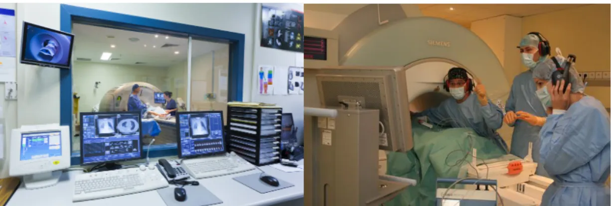
FIGURE 2.7: Left: A view of the surgical room from technicians area.
Right: Surgeon’s communication with the technician.
FIGURE 2.7 shows an MRI-based real-time image-guided surgery. The surgeon is presented with the MRI image which is constantly acquired from the MRI machine in real-time. The MRI machine is controlled by the technician in the control room and has a view of the operation area through a window. The surgeon directs him to control the
MRI image view using sign directions. The sign interaction is specifically used because the MRI machine makes a loud noise during its operation. Contrary to this, in a typical laparoscopic surgery, the endoscope is controlled by the lead surgeon’s assistant who can also observe the screen and can be instructed verbally by the surgeon to adjust the viewpoint. Though this scenario is communication-wise less complicated than that with the MRI machine imaging, a comprehensive interaction between the surgeon and his technician is always required. The surgical team acquires these abilities by periodic rigorous training. Augmented-reality techniques aim to ease this interaction, which in turn, will reduce training hours for the surgical team.
In the case of 3D volumetric data, three standard methods are used: slice-based, surface-based and direct volume rendering. In the most commonly used slice-based method, orthogonal slice images of the patient (pre or intra operative) are displayed. These are called Axial, Sagittal and Coronal plane slices. If a series of consecutive slices is present, a 3D image can be constructed. With the tracking data acquired from the sensors mounted on the laparoscopic tools, the path of the tool can be rendered on the screen with the 3D volume image of patient’s anatomy. In practice, surgeons choose to view 3D renderings in pre-operative surgical planning. During surgery, they prefer to see the different orthogonal slices on their screens in real-time. This practice also avoids the computational overhead of 3D real-time rendering and pro-vides a clear 2D view of the necessary slices to the surgeon. Authors of [Tyn+15] present a visualization-based needle insertion surgery. FIGURE2.8shows the image on the display of the surgeon while the tool (needle) is observed in each frame during surgery. In this figure, the tool is not tracked by any sensors but only observed by the surgeon on the screen. Tracking the tool using sensors can provide additional control on the visualization such as automatically adjusting the viewpoint with respect to the tracked tool.
FIGURE 2.8: A: Possible path of needle insertion. Part of the
pre-planning. B: The path chosen before the needle insertion. C and D: Real-time progress of needle insertion.(Images from [Tyn+15])
![FIGURE 3.5 shows the position response of a 2D PSD after computing the position by using the formulae from [CS10].](https://thumb-eu.123doks.com/thumbv2/123doknet/14499955.527654/55.892.202.623.577.867/figure-shows-position-response-computing-position-using-formulae.webp)