Creep and fluidity of a granular packing under shear stress
124
0
0
Texte intégral
(2) UNIVERSITÉ D’ORLÉANS. ÉCOLE DOCTORALE SCIENCES ET TECHNOLOGIES Institut des Sciences de la Terre d’Orléans THÈSE présentée par : Van Bau NGUYEN soutenue le : 03 Novembre 2011 pour obtenir le grade de : Docteur de l’Université d’Orléans Discipline/ Spécialité : Géosciences. Fluage et fluidité d’un empilement granulaire sous contrainte THÈSE dirigée par : Ary BRUAND Eric CLÉMENT RAPPORTEURS : Farhang RADJAI Yoël FORTERRE JURY : M. Jean-Louis ROUET M. Christian HARTMANN M. Farhang RADJAI M. Yoël FORTERRE M. Ary BRUAND M. Eric CLÉMENT. Professeur, Université d’Orléans Professeur, Université Paris VI Directeur de recherche, CNRS Chargé de recherche, HDR, CNRS. Université d’Orléans, Examinateur IRD, Examinateur CNRS, Rapporteur CNRS, Rapporteur Université d’Orléans, Directeur de thèse Université Paris VI, Directeur de thèse.
(3)
(4) R EMERCIEMENTS J’aimerais tout d’abord remercier les membres du jury qui ont accepté d’évaluer mon manuscrit de thèse. Je remercie particulièrement mes directeurs de thèse, Eric Clément et Ary Bruand, pour avoir orienté la thèse dans le bon sens, mais aussi pour le temps qu’ils m’ont consacré. Je remercie des collègues dans mon bureau : Olivier Dron, Nicolas Champagne et Romain Mari qui m’ont donné beaucoup des conseil utiles pendant ma thèse. Je remercie à toute ma famille : Lan Phuong Bui, Minh Khoi Nguyen.... qui m’ont constamment soutenu pendant mes études.. iii.
(5)
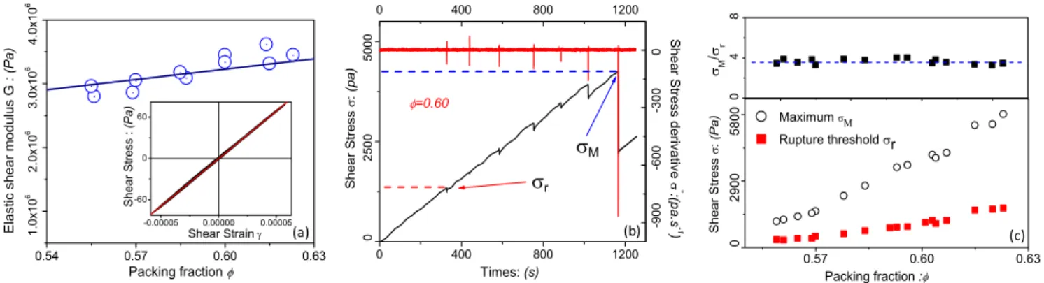
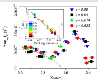
(6) R ÉSUMÉ L’objectif principal de la thèse a été d’identifier expérimentalement les comportements mécaniques et rhéologiques de milieux granulaires dans un environnement de complexité croissante. En particulier, je me suis intéressé aux phénomènes de fluage sous contrainte en essayant de mieux comprendre l’impact des vibrations et la présence d’une faible quantité d’eau piégée entre les grains. Au début de ma thèse, j’ai monté un système cissométrique permettant de réaliser des tests mécaniques de fluage. Ce dispositif a spécialement été conçu pour accéder aux domaines de très faibles contraintes cisaillements et de déformations. En outre, c’est un système de mesure relativement simple qui peut être adapté facilement aux problèmes de terrain et ainsi, à terme, permettre d’évaluer les caractéristiques mécaniques d’un sol " réel ". Au laboratoire, j’ai étudié les propriétés fondamentales de fluage sous contrainte d’un empilement granulaire de billes de verre de taille d = 200µm sous le seuil de Coulomb. Une originalité de mon montage a été de mettre au point un système de lit fluidisé qui, en alliant flux d’air et vibration, m’a permis de fabriquer des empilements de compacité initiale contrôlée. En partant d’une situation très décompactée, par impacts successifs, on peut obtenir des compacités plus importantes. Grâce à des mesures de perte de charge, on accède à la perméabilité moyenne de la structure granulaire, j’ai établi une relation d’étalonnage entre perméabilité et compacité ; cela permet de remonter précisément à la compacité. Ce montage permet en outre, par injection dans le granulaire d’un gaz saturé en vapeur d’eau, d’imposer sous un faible gradient thermique une condensation et d’obtenir une quantité contrôlée d’eau piégée dans l’empilement. Cette méthode permettra par la suite d’aborder le cas de granulaires cohésifs. Cette étude a mis en évidence que les seuils de Coulomb varient fortement avec la compacité, mais en plus , on a mis en évidence une contrainte σr appelée " contrainte de première rupture " qui traduit des réorganisation internes dans l’empilements et qui est d’environ 1/3 de la contrainte seuil maximale. En outre, grâce à la précision de la mesure de déformation, on a obtenu les réponses élastiques à de petits cycles en contrainte et on a établi que le module cisaillement élastique G augmente linéairement en fonction de la compacité, en accord avec le modèle d’élasticité non-linéaire de Hertz (modèle de champ moyen). En absence de vibration, nous avons réalisé une étude paramétrique complète du fluage en variant systématiquement la compacité et la contrainte de cisaillement. Dans tous les cas nous avons mise en évidence une dynamique de déformation logarithmique pour temps longs. Il a été montré qu’une dynamique de déformation logarithmique peut-être observée même sous de faibles niveaux de contrainte. Elle peut être caractérisée empiriquement par un modèle de rhéologie initialement introduit par Derec et al.[13] mettant en jeu une variable dynamique interne appelé "fluidité". Les deux paramètres du modèle (fluidité initiale et coefficients de vieillissement) sont mesurés en fonction de la compacité et du niveau de contrainte. De plus, bien avant le seuil de Coulomb, un seuil dit de "micro-rupture" est observé, correspondant à des réarrangements v.
(7) vi. RÉSUMÉ. granulaires qui ont pour effet d’augmenter le coefficient de vieillissement, c’est à dire de ralentir la dynamique de fluage avant la rupture finale correspondant au seuil de Coulomb. Cette étude a été prolongée pour des empilements sous vibration et en présence d’une quantité d’eau ajoutée. Notre étude sur les seuils de contrainte, l’élasticité effective et la dynamique de fluage, a été prolongée pour des empilements sous vibration générés par des transducteurs piézo-électriques enfouis sous la surface. On a trouvé aussi que les seuils de Coulomb à différentes compacités, pouvaient être notablement diminués en fonction du niveau de vibration même pour de faibles accélérations moyennes. On constate que le module élastique est lui aussi diminué par la vibration et que sa valeur est quasiment réversible pour des temps faibles d’application de la vibration. On a étudié aussi l’influence des formes spectrales des vibrations sur la dynamique de fluage. Pour une même fréquence d’excitation et un même niveau d’énergie élastique dans le granulaire, deux types de sources ont été étudiés : une vibration sinusoïdale produisant une réponse très harmonique et des créneaux produisant un spectre beaucoup plus large. Une faible quantité d’eau peut aussi être ajoutée et ainsi modifier les propriétés mécaniques par la présence de ponts capillaires. Nous avons mis au point et étalonné une méthode d’injection d’un air humidifié à une température légèrement supérieure à la température ambiante. On a vérifié (par pesée avec une micro balance) que la condensation dans le granulaire augmentait avec ce temps d’injection et que la quantité d’eau condensée dépendait faiblement de la hauteur. C’est donc une méthode intéressante pour étudier les granulaires faiblement humides. Des expériences préliminaires montrent la dépendance des seuils de Coulomb de la réponse élastique et de la dynamique de fluage avec la quantité d’eau piégée..
(8) A BSTRACT The main objective of the thesis was to identify experimentally the mechanical and rheological behavior of granular medium in an environment varying in complexity. In particular, I was interested to creep phenomenon under stress in trying to understand better the impact of vibration and the presence of a small amount of water trapped between the grains. At the beginning of my thesis, I set-up a system to perform mechanical creep tests. This device has been specially designed to access to areas of very low shear stresses and deformations. In addition, it is a device that can be easily adapted to field environment, and this to assess the mechanical properties of ’real’ soils. In the laboratory, I studied the basic properties of creep strain of a granular resulting from the packing of glass beads with means diameter d = 200µm under the Coulomb threshold. An originality of my set-up was the fluidized bed, which uses air flow and vibration, and this allows the control of the initial packing fraction. Starting from a very loose packing, and using successive mechanical, a higher compacity can be reached. Through pressure difference measurement, we determine the average permeability of the granular medium. Then, I established a calibration relationship between the permeability and the packing fraction, which can be used to go back precisely to the packing fraction. This setup also allows us to inject in a granular medium air saturated with water vapor, imposed under low thermal gradient and condensation to obtain a controlled amount of water content. It will be possible to apply this method to the case of cohesive granular medium. This study showed that the Coulomb thresholds varies strongly with the packing fraction. In addition, it showed a stress σr called "the first rupture", that results from internal reorganizations in the granular medium and which is approximated 1/3 of the maximum stress threshold. Moreover, thanks to the precision of measuring deformation, we obtained the elastic response with small stress cycles, and we found that the shear elastic modulus G increases linearly with the packing fraction, in agreement with the model of nonlinear elasticity of Hertz (mean field). In the absence of vibration, we performed a parametric study of creep in varying the packing fraction and shear stress. In all cases, we found the dynamics of logarithmic creep for long times. The logarithmic creep can be observed even under low stress levels. It can be empirically characterized by a rheological model introduced by Derec et al.[13], involving an internal dynamic variable called "fluidity". The two model parameters (initial fluidity and coefficient of aging) are measured in terms of packing fraction and the stress level. Before the Coulomb threshold, the "first-rupture" is observed, that have the effect of increasing the aging coefficient. It slows creep dynamics before the final threshold corresponding to the Coulomb threshold. This study was extended to granular medium under vibration and in the presence of water added. Our study on stress threshold, the elastic modulus and dynamics of creep, has been extended to granular medium under vibration generated by piezoelectric transducers buried under the surface. We also found that the Coulomb thresholds at different packing fractions, could be significantly reduced depending on the level of vibration even at low accelerations averages. It is found vii.
(9) viii. ABSTRACT. that the elastic modulus is also reduced by the vibration and its value is almost reversible for lowtime application of vibration. We also studied the influence of the spectral shapes of vibration. For the same excitation frequency and the same level of elastic energy in the granular, two types of vibration were studied : a sinusoidal vibration producing a very harmonic response and a square vibration producing a much wider spectrum. A small amount of water can be added and thus modifies the mechanical properties by the presence of capillary bridges. We developed and calibrated a method for injecting a humidified air at a temperature slightly above room temperature. We checked (by weighing with a micro scale) that in the granular medium the condensation increased with the injection time and that the amount of water depended weakly on the height. This is an interesting method to study a wet granular. Preliminary experiments show the dependence of the Coulomb threshold of the elastic response and dynamic creep with the amount of water content..
(10)
(11) TABLE DES MATIÈRES. Remerciements. iii. Résumé. v. Abstract. vii. Table des matières 1. 2. x. Introduction générale 1.1 Introduction . . . . . . . . . . . . . . . . . . . . . . . . . . . . . . . . . . . . 1.2 Jamming et RCP d’un milieu granulaire . . . . . . . . . . . . . . . . . . . . 1.3 Propriétés mécaniques et déformation par fluage d’un milieu granulaire 1.3.1 Relation entre contrainte et déformation . . . . . . . . . . . . . . . 1.3.2 Réponse élastique d’un milieu granulaire . . . . . . . . . . . . . . 1.3.3 Modèle de Hertz . . . . . . . . . . . . . . . . . . . . . . . . . . . . . 1.3.4 Seuil de rupture, écoulement du milieu granulaire . . . . . . . . . 1.3.5 Fluage . . . . . . . . . . . . . . . . . . . . . . . . . . . . . . . . . . . 1.4 Effet des vibrations sur un milieu granulaire . . . . . . . . . . . . . . . . . 1.5 Mécanismes de cohésion entre grains par capillarité . . . . . . . . . . . . 1.5.1 Granulaires mouillés non saturés . . . . . . . . . . . . . . . . . . . 1.5.2 Ponts capillaires : forces capillaires . . . . . . . . . . . . . . . . . . 1.5.3 La cohésion macroscopique . . . . . . . . . . . . . . . . . . . . . .. . . . . . . . . . . . . .. . . . . . . . . . . . . .. . . . . . . . . . . . . .. . . . . . . . . . . . . .. . . . . . . . . . . . . .. 1 2 3 4 4 5 5 7 9 13 16 16 16 18. La cellule de cisaillement 2.1 Motivations . . . . . . . . . . . . . . . . . . . . . . . . . . . . . . . . . . . . . . . . 2.2 Dispositif expérimental . . . . . . . . . . . . . . . . . . . . . . . . . . . . . . . . . 2.2.1 Compacité contrôlée par la méthode de tapping . . . . . . . . . . . . . 2.2.2 Permeability as a function of packing fraction . . . . . . . . . . . . . . . 2.2.3 Préparation d’un échantillon avant les tests mécaniques . . . . . . . . 2.2.4 Mesure de la contrainte de cisaillement . . . . . . . . . . . . . . . . . . 2.2.5 Mesure de la déformation . . . . . . . . . . . . . . . . . . . . . . . . . . . 2.2.6 Système d’acquisition . . . . . . . . . . . . . . . . . . . . . . . . . . . . . 2.3 Empilement granulaire sous faible vibration . . . . . . . . . . . . . . . . . . . . 2.3.1 Activateurs piézoélectriques . . . . . . . . . . . . . . . . . . . . . . . . . 2.3.2 Accélération . . . . . . . . . . . . . . . . . . . . . . . . . . . . . . . . . . . 2.3.3 Calibration du RMS d’accélération pour une tension entrée créneau . 2.3.4 Calibration du RMS d’accélération pour une tension entrée sinusoïde. . . . . . . . . . . . . .. . . . . . . . . . . . . .. . . . . . . . . . . . . .. . . . . . . . . . . . . .. 19 20 20 21 22 24 25 25 27 28 28 29 32 32. x. . . . . . . . . . . . . .. . . . . . . . . . . . . ..
(12) TABLE DES MATIÈRES. xi . . . . . . . .. 33 34 34 35 36 37 37 38. 3. Réponse élastique et fluage d’un milieu granulaire 3.1 Introduction . . . . . . . . . . . . . . . . . . . . . . . . . . . . . . . . . . . . . . . . . . . 3.2 Réponse élastique . . . . . . . . . . . . . . . . . . . . . . . . . . . . . . . . . . . . . . . . 3.2.1 Méthode de mesure . . . . . . . . . . . . . . . . . . . . . . . . . . . . . . . . . . 3.2.2 Discussion sur la rigidité de la pale . . . . . . . . . . . . . . . . . . . . . . . . . 3.2.3 Champ moyen de l’élasticité de Hertz . . . . . . . . . . . . . . . . . . . . . . . 3.3 Réponse à une rampe de contrainte de cisaillement . . . . . . . . . . . . . . . . . . . . 3.3.1 Résistance d’un empilement soumis à une vitesse de chargement constante 3.3.2 Influence de la vitesse chargement . . . . . . . . . . . . . . . . . . . . . . . . . 3.3.3 Influence de la raideur du ressort . . . . . . . . . . . . . . . . . . . . . . . . . . 3.3.4 Influence de l’humidité relative . . . . . . . . . . . . . . . . . . . . . . . . . . . 3.4 Réponse à un fluage . . . . . . . . . . . . . . . . . . . . . . . . . . . . . . . . . . . . . . . 3.4.1 Feedback . . . . . . . . . . . . . . . . . . . . . . . . . . . . . . . . . . . . . . . . 3.4.2 Déformation par fluage . . . . . . . . . . . . . . . . . . . . . . . . . . . . . . . . 3.4.3 Glissement aux parois extérieures . . . . . . . . . . . . . . . . . . . . . . . . . . 3.4.4 Déformation logarithmique par fluage . . . . . . . . . . . . . . . . . . . . . . . 3.4.5 Vibrations résiduelles . . . . . . . . . . . . . . . . . . . . . . . . . . . . . . . . . 3.4.6 Modèle théorique de fluidité . . . . . . . . . . . . . . . . . . . . . . . . . . . . . 3.5 Spectroscopie par diffusion multipe de la lumière (DWS) . . . . . . . . . . . . . . . . . 3.5.1 Mesures locales de déformation . . . . . . . . . . . . . . . . . . . . . . . . . . . 3.5.2 Dispositif expérimental . . . . . . . . . . . . . . . . . . . . . . . . . . . . . . . . 3.5.3 Réponse à une rampe de contrainte . . . . . . . . . . . . . . . . . . . . . . . . . 3.5.4 Déformation par fluage . . . . . . . . . . . . . . . . . . . . . . . . . . . . . . . . 3.5.5 Dissipation d’énergie . . . . . . . . . . . . . . . . . . . . . . . . . . . . . . . . . 3.6 Conclusion . . . . . . . . . . . . . . . . . . . . . . . . . . . . . . . . . . . . . . . . . . . .. 39 40 41 41 42 45 46 46 49 51 52 52 52 53 54 55 58 58 63 63 64 66 68 70 70. 4. Infuence des vibrations sur la réponse élastique et le fluage dynamique 4.1 Introduction . . . . . . . . . . . . . . . . . . . . . . . . . . . . . . . . . 4.2 Mesure du module élastique . . . . . . . . . . . . . . . . . . . . . . . . 4.2.1 Influence des vibrations . . . . . . . . . . . . . . . . . . . . . . 4.2.2 Réversibilité . . . . . . . . . . . . . . . . . . . . . . . . . . . . . 4.3 Réponse à une rampe de contrainte . . . . . . . . . . . . . . . . . . . 4.4 Réponse du fluage à une contrainte constante . . . . . . . . . . . . . 4.5 Conclusion . . . . . . . . . . . . . . . . . . . . . . . . . . . . . . . . . .. 71 72 72 72 73 74 76 80. 2.4. 2.5 2.6. 5. 2.3.5 Homogénéité du RMS d’accélération . . . . . . . . . . . . . . . . . Empilement granulaire humide . . . . . . . . . . . . . . . . . . . . . . . . . 2.4.1 Dispositif expérimental utilisé pour obtenir un flux d’air humide 2.4.2 Mesure de la quantité d’eau . . . . . . . . . . . . . . . . . . . . . . 2.4.3 Influence du gradient de température . . . . . . . . . . . . . . . . 2.4.4 Courbe de calibration . . . . . . . . . . . . . . . . . . . . . . . . . . Pont capillaire . . . . . . . . . . . . . . . . . . . . . . . . . . . . . . . . . . . Conclusion . . . . . . . . . . . . . . . . . . . . . . . . . . . . . . . . . . . . .. . . . . . . .. . . . . . . .. . . . . . . .. . . . . . . . .. . . . . . . .. . . . . . . . .. . . . . . . .. . . . . . . . .. . . . . . . .. . . . . . . . .. . . . . . . .. . . . . . . . .. . . . . . . .. . . . . . . . .. . . . . . . .. . . . . . . .. Influence de la quantité d’eau ajoutée 81 5.1 Introduction . . . . . . . . . . . . . . . . . . . . . . . . . . . . . . . . . . . . . . . . . . . 82 5.2 Module élastique G . . . . . . . . . . . . . . . . . . . . . . . . . . . . . . . . . . . . . . . 82.
(13) 5.3 5.4 5.5. Influence de la quantité d’eau sur le seuil de Coulomb . . . . . . . . . . . . . . . . . . 83 Fluage . . . . . . . . . . . . . . . . . . . . . . . . . . . . . . . . . . . . . . . . . . . . . . . 84 Conclusion . . . . . . . . . . . . . . . . . . . . . . . . . . . . . . . . . . . . . . . . . . . . 86. Annexe Bibliographie. 89 105.
(14) CHAPITRE. 1. I NTRODUCTION GÉNÉRALE. Contents 1.1 1.2 1.3. 1.4 1.5. Introduction . . . . . . . . . . . . . . . . . . . . . . . . . . . . . . . . . . . . Jamming et RCP d’un milieu granulaire . . . . . . . . . . . . . . . . . . . . Propriétés mécaniques et déformation par fluage d’un milieu granulaire 1.3.1 Relation entre contrainte et déformation . . . . . . . . . . . . . . 1.3.2 Réponse élastique d’un milieu granulaire . . . . . . . . . . . . . 1.3.3 Modèle de Hertz . . . . . . . . . . . . . . . . . . . . . . . . . . . . 1.3.4 Seuil de rupture, écoulement du milieu granulaire . . . . . . . . 1.3.5 Fluage . . . . . . . . . . . . . . . . . . . . . . . . . . . . . . . . . . Effet des vibrations sur un milieu granulaire . . . . . . . . . . . . . . . . . Mécanismes de cohésion entre grains par capillarité . . . . . . . . . . . . 1.5.1 Granulaires mouillés non saturés . . . . . . . . . . . . . . . . . . 1.5.2 Ponts capillaires : forces capillaires . . . . . . . . . . . . . . . . . 1.5.3 La cohésion macroscopique . . . . . . . . . . . . . . . . . . . . .. 1. . . . . . . . . . . . . .. . . . . . . . . . . . . .. . . . . . . . . . . . . .. . . . . . . . . . . . . .. . . . . . . . . . . . . .. 2 3 4 4 5 5 7 9 13 16 16 16 18.
(15) 2. CHAPITRE 1. INTRODUCTION GÉNÉRALE. 1.1 Introduction This work has originated from a collaboration between the Laboratoire de Physique et Mécanique des Milieux Hétérogènes (PMMH) in Pierre and Marie Curie University, a physics laboratory and the Institut des Sciences de la Terre d’Orléans (ISTO) in University of Orléans specialized in soil-science. The objective of the current collaboration is to provide a better understanding to a class a granular systems called "sandy soils". This type of soil is composed of a granular matrix made of sandy grains of size reaching fractions of a millimeter. A second granular scale is mixed to the first one and consists of fine micro particles, essentially made of clay. The fraction of clay is very small and provides marginal cohesion to the packing. This last system is known in the soilscience community for its inherent structural instability and all the problem it poses in the context of agriculture and food production in deserted areas of the planet. The results of my thesis is not directly applied to sandy-soils, however it may hopefully establish an original conceptual direction towards a better understanding of restructuration process due to mechanical constraints in loosely cohesive granular materials. More generally, granular materials may come in a very large variety of shapes, sizes and intergranular interactions. Usually, the expression "granular material" is restricted to assemblies of macroscopic particles such that thermal processes are quite irrelevant to describe the macroscopic physics and the mechanical properties. In the last decades, an intense scientific activity has been devoted to the understanding their constitutive relations. In the physics community the effort was principally focused on the fundamental understanding of simplified granular models such as idealized packing of spheres. In spite its relative simplicity, it was proven to be a very successful approach to identify generic behavior and clarify fundamental mechanisms at work for example in the rheology of an assembly of grains interacting microscopically through solid contacts. It has helped to shed new light on much more complex systems involving non only granular materials but also belonging to the class of complex fluids. This reductionist vision is currently evolving by the addition of elements of increasing complexity. My thesis follows this line of thought. First, I will consider the mechanical response of packing of dry glass beads. Then, I will study the changes in behavior due to the addition of weak vibrations. Finally, I will consider the case where a small amount of water is added to the packing. The purpose of this first chapter is to present the concepts I will use in the framework of my thesis. First, I will present the basics for the "jamming transition" of a packing of grains and its relation to other complex fluids and glassy systems. Then, I will discuss the notion of elastic response of a granular packing. To this purpose, I will present the standart Hertz model for granular contacts rigity and its consequence on the relationship between the shear elastic modulus and the packing fraction. Then, I will describe the generic response of a granular material to shear and introduce the MohrCoulomb theory which is currently used to characterize the shear strength of a granular medium. Thereafter, I will discuss the creep phenomenonology and empirical models used to describing long time deformation in soils. To complement the description of lond time relaxation, I will present also some notions of the recent descrition of complex fluid rheology involving internal complex relaxation mechanisms. I will then introduce the notion of material ’fluidity’ which is a base of analysis of my experimental results. After that, I will review some elements describing the influence of vibration on the mechanical responses and flow properties of a granular medium. Finally, I will present a brief summary of the.
(16) 1.2. JAMMING ET RCP D’UN MILIEU GRANULAIRE. 3. works that have been devoted to the role of water content in a granular packing. In particular, I will discuss how the cohesion of wet granular matter may change with an amount of water added.. 1.2 Jamming et RCP d’un milieu granulaire For a granular assembly at low packing fraction φ, the spatial distribution of grains can be such that at zero agitation, particles do not touch each other and thus, the granular pressure is p = 0. If energy is transfered to the system via some external driving, the particles will collide as in a gas or in a liquid. In this last case, the square of velocity fluctuations is a good macroscopic variable decribing the transfer of momentum and energy. This is the so-called granular gas state. An equation of state linking the pressure to granular temperature can then be established. In the limit of zero confining pressure and zero temperature, as φ is increased, the granular system will reach a value φ j , at which the particles just touch and lock into a rigid but disordered structure. To increase φ further one has to exert an external confining pressure p > 0 and compress elastically the grains. This is the ’jamming transition’ : a transition from a liquid-like state to a rigid solidlike state charaterize by a positive macroscopic elastic shear modulus. The critical nature of the jammed state and the values of φ j at the jamming transition depend on the dimensionality D of the system as well as some microscopic properties of the individual particles.. F IGURE 1.1: Jamming phase diagram proposed by Liu and Nagel [53]. In the absence of inter-granular friction (µ = 0), the jamming point will correspond to a critical number of contact : z c = 2D. For µ 6= 0, the addition of rotational degrees of freedom lead to a drastic change in the value of the critical number of contacts : Zc = D +1. As a consequence, grains with friction can undergo a jamming processes at much lower packing fraction [26] than frictionless particles. For spherical, frictionless and rigid particles, the density at which a packing is jammed is often called the ’random close packing’ (RCP) density φr cp . From numerous experiments and numerical simulations, one finds that for large number of particles, the random close packing densities are [43, 82] : in 2D φr c p ≈ 0.84 and in 3D φr cp ≈ 0.64. In spite of the many consistent experimental and numerical determinations of the φr cp values, a clear mathematical definition of what RCP means and a precise analytical calculation of it, remain elusive. In practice, a rigid assembles of frictional spheres can experience a jammed state for a packing fraction range : 0.55 ≤ φ ≤ 0.635..
(17) 4. CHAPITRE 1. INTRODUCTION GÉNÉRALE. In 1998, Liu and Nagel [53] sketched a speculative phase diagram suited to unify the description of many different materials such as granular materials, pastes, dense suspensions, foams, glasses etc... (see fig.1.1). All these systems display a severe slowing down of their dynamics leading to quasi blockade of the flow which is usually called "jamming". These authors suggested that temperature, packing fraction and stress can play a similar role as jamming would occur at low temperature, low applied stress and low volume per grain. For a granular medium, as we noted, the thermodynamic temperature plays a priori no role. However, a timely question is to understand to which extend external mechanical vibration could play a role similar to the thermodynamic temperature for glassy thermal systems.. 1.3 Propriétés mécaniques et déformation par fluage d’un milieu granulaire 1.3.1 Relation entre contrainte et déformation. F IGURE 1.2: Schematic representation of a direct shear test (left) and variation of the shear stress as a function of shear strain as a function of the granular medium compacity (right).. A well known method for characterizing the shear-strain relation for a granular medium is for example, the direct shear test (sketch on fig.1.2 left). In this test, the shear stress is simply calculated by the relation : σ = F h /S (1.1) where S is the contact surface area, F h is the shear force for a confining pressure P = F v /S. During deformation, dense samples tend to dilate, and loose ones to contract. This is the "dilatancy effect" first noted and qualitatively explained by O.Reynolds in the X I X t h century. At high packing fractions, the shear-strain curve presents a peak of shear stress called the maximum shear stress. If one continues to shear, the resistance of the material decreases toward a constant value called the residual resistance of the material. On the other hand , if the packing fraction is low, one does not observe a peak of resistance, but only the residual resistance at large deformation. These results are very generic and were found in other shear tests like : the annular shear or the triaxial test..
(18) 1.3. PROPRIÉTÉS MÉCANIQUES ET DÉFORMATION PAR FLUAGE D’UN MILIEU GRANULAIRE5 Note that for all experimental tests, one observes in practice a strong localization of the deformation field called a "shear band". Typically shear bands occurs at the stresses around the peak value for dense packing and when the stress-strain curve saturates for loose packing. In dry granular packing, the shear-band lateral extension is of a few grain size. At low deformation, one observes an elastic regime (fig.1.2 left). In this regime, the relations between the shear stress and the shear strain are linear and reversible. For an ideal shear test, the slope would correspond to the shear elastic modulus G at a given confining pressure P .. 1.3.2 Réponse élastique d’un milieu granulaire. F IGURE 1.3: Empirical behavior of a large class of granular materials based on the response to shear deformation [33] . In practice, the elastic domain has been tested by different experimental methods (static or dynamic). Static experiment were performed by very small charge-discharge cycles of shear stress or shear strain, at a low frequency, in order to determine the shear modulus G. On the other hand, dynamic experiments, mostly using the sound wave propagation at a high frequencies (some k H z) were performed. An elastic behavior is actually identified under very small deformations (fig.1.3). The deformation level corresponding to the transition between the elastic and plastic behavior can vary by one to two orders of magnitude [33] according to the material and the nature of granular interactions. Fig.1.3 shows that, for material such as sand or clay. Measurements were performed at very low deformation level to identify the elastic domain (below 10−4 (m/m)). In this thesis, we developed an experimental set-up suited to monitor deformations in this range (Chapter3).. 1.3.3 Modèle de Hertz First, we present the classical theory of inter-particular forces between two spheres for a linear material elasticity. When two spheres of radius R are compressed against each other by a force F , they are flattened in the vicinity of the contact zone in the form of a disk of radius a as the distance between their centers decreases of value δ. The deformation is the displacement relative to the size.
(19) 6. CHAPITRE 1. INTRODUCTION GÉNÉRALE. characteristic of the deformed area δ/a. From Hooke’s law, the relationship between the average stress σ and the deformation yields : FN δ σ = 2 ∝ Eg (1.2) a a where E g the grain Young’s modulus, and the relationship between the radius of the contact area and the displacement is : a 2 ≈ Rδ. Then, the contact force scales in a non-linear way with δ as : δ F N ∝ R 2 E g ( )3/2 R. (1.3). F IGURE 1.4: Schematic representation of the contact between two spheres with a displacement δ (left) and relation between the force and the displacement (right).. The full mechanical calculation was first carried by Hertz [45] and he found that the normal force between two spheres of identical radii is : 8g. FN =. 3(1 − νg ). δ R 2 ( )3/2 R. (1.4). where G g is the shear modulus of the material and νg the Poisson ratio. If the spheres have different 1 R2 radii of curvature, it can be shown that : R = R2R1 +R2 . The previous qualitative argument can be extended to the shear stiffness calculation. If one calls F T , the tangential force component between two spheres, with F T < µs F N as a condition for no slip, where µs is the coefficient of static friction, the two grains undergo a small relative tangential displacement ∆s, the transverse deformation scale is ∆s/a. The relationship between the mean stress and the shear deformation can be expressed as : FT ∆s ∝ µg ( ) 2 a a. (1.5). where µg is the shear modulus of the grains, the tangential force is then : FT =. δ R( )1/2 ∆s 2 − υg R 8µg. (1.6).
(20) 1.3. PROPRIÉTÉS MÉCANIQUES ET DÉFORMATION PAR FLUAGE D’UN MILIEU GRANULAIRE7 when the Coulomb limit is reached, the frictional force is F T = µs F N . Many numerical model are based on such a representation of granular interaction to account for normal and tangential contact forces. This the so-called Hertz-Midlin model. However, as Mindlin himself noticed, there is a mechanical issue associated with the tangential stress at contact. Shear stress can be shown to diverge near the contact edge as in a mode II fracture [45]. This creates a plastic zone at the outer rim of the contact surface. This is an inherent source of dissipation which is rarely taken into account. Another limitation of this description is the presence of plastic deformations at contact, even at moderate external confining stress. These irreversible processes can be due (i) to the stress amplificaction at contact such that the material hardness limit is reached and (ii) microscopic asperities that can be also be plastified (this is the origin of solid friction). So, even though the HerzMindlin model provides a firm base for macroscopic calculation of elastic properties, one has to bear in mind that for all "real" granular packing, due to the physics at nanoscopic if not microscopic scales, irreversible plastic processes do indeed take place. In the framework of the Hertz-Mindlin model, several authors have obtained expressions for the macroscopic bulk and shear elastic modulii (see a review of models and references in [20]). For example a derivation of the macroscopic shear modulus yields the expression : G =(. µg 3π(1 − υg ) 1/3 1 3 +² ) (φz)2/3 ( P) 1 − υg 2 − υg 5π 2υg. (1.7). This equation expresses two limits : no sliding friction between the grains (² = 0) or infinite friction between the grains (² = 1). Note also that in this expression, a continuous variation of 0 ≤ ² ≤ 1 would correspond to the "tangential coupling model " studied numerically by Makse et al. [20]. Note importantly that this result is a Mean-Field approximation introducing a crucial assumption in the derivation, i.e. a direct relation between the macroscopic and microscopic strains. This has been shown to be a poor approximation to the microscopic granular displacement and leads to quantitative failure of the theory. This failure is especially important for the shear modulus [20]. Experimentally, the relationship between the elastic modulus and the confining pressure has also been studied by acoustic methods [22, 21, 94]. In practice, the scaling law G ∝ P 1/3 is not fully recovered and many open questions remains such as to understand the relation between the packing fraction and the mean number of contacts per grain Z . Numerical simulations have explored this relation for packing of frictionless spheres, near the jamming threshold. The mean number of contacts per grain is a function of the volume fraction [25] and the relation is for φ > φc : Z − Zc ≈ (φ − φc )1/2. (1.8). where in 3D the critical contact number is Zc = 6 [25] and φc ≈ 0.639. For packing with friction, a critical like behavior can be recovered near jamming with a friction dependent value for the critical number of contacts Zc (µ) [88]. Far from the jamming "critical" region, the situation is much less clear as in general, there is no one-to-one relation between Z and φ [2] and the macroscopic mechanical properties can be strongly preparation dependent [89].. 1.3.4 Seuil de rupture, écoulement du milieu granulaire In soil mechanics, granular material studies are motivated by the desire to understand the failure of foundations, slopes, and soils. The basic model which account for the rupture threshold is the Mohr-Coulomb model [16]. Its phenomenlogy follows the laws of solid on solid Coulomb friction but is adapted to the fact that the rupture problem in granular matter is essentially a tensorial.
(21) 8. CHAPITRE 1. INTRODUCTION GÉNÉRALE. issue. This model is described by the stability condition : σ ≤ σn .t anϕ. (1.9). Where σ is the shear stresses, σn the normal stress and the angle ϕ is called the internal friction angle of the material. These stress components are taken in the reference frame corresponding to the eigen-directions of the stress tensor. With a cohesive granular medium, one must add a cohesion term c and the stability condition becomes : σ ≤ σn .t anϕ + c. (1.10). This law expresses that the material maintains its structure as long as the inequality is satisfied and yield occurs when the equality is reached. The angle of internal friction depends on the packing fraction (or the void ratio for soil-mechanicists). Many empirical models exist to account for this dependence. A celebrated one is the study of Caquot et Kérisel [11] who proposed the following relation to relate internal angle and compacity : e.t anϕ = K. (1.11). where K is a constant which depends only on the nature of the material and e is the void ratio calculated by the relation : e = (1−φ)/φ. Actually, there is no authoritative relation but the increase of ϕ with φ is in practice a well establihed result. The angle of internal friction depends also on the shape and the surface properties of the grains. An interesting heuristic model is the Rowe model [67] which considers a simple piling made of a bead A put on two beads B and C (see fig.1.5). The bead A sustain a normal force N and a tangential force T . The rupture limit corresponds to the force T just sufficient to move the bead A under the constant force N . Considering that the bead friction coefficient is µs = t an(ϕs ) and β is the angle between the tangential contact plane and the horizontal direction (see see fig.1.5), a simple calculation of the mechanical conditions of rupture yields a value for the ratio of the tangential force to the normal force : T = tan ϕ = tan(β + ϕs ) (1.12) N where ϕ represents the angle of internal friction. This model is certainly naive but it shows in a simple way the combined influence on ϕ of the packing geometry and compacity (through β) and of the granular friction (through φs ).. F IGURE 1.5: Rowe model [67] for the internal friction of a packing..
(22) 1.3. PROPRIÉTÉS MÉCANIQUES ET DÉFORMATION PAR FLUAGE D’UN MILIEU GRANULAIRE9 Note that the Mohr-Coulomb theory can be extented to account for the large plastic deformation of granular materials. The qualitative phenomenology described in 1.3 can be reproduced by sophisticated incremental plasticity model [65] which are based on many experimental tests to get empirical constitutive parameters. However, in this type of approach, which is the base for soil mechanics calculations, no real time dependence is contained. From the Rowe formulation (see equ.1.12), one can simply see that as long as compacity (encripted in β) and intergranular friction do not change with time, the Coulomb limit bears no dependence with time either. However, many tribology studies show that solid on solid friction coefficients generically display a slow ageing dependence due to nanoscopic plastic processes. Immediatly one can see that at long time scale, this could influence on the constitutive properties of granular matter [38] and also eventually change on the long time, the structual properties of the packing.. 1.3.5 Fluage As seen previously, mechanical properties of granular packing are usually described phenomenologically by rate independent constitutive relations [8]. However, there are also compelling experimental evidences that for granular assemblies in "real" environment (i.e. finite temperature, temperature variations or background noise), this limit is just a short-time approximation and that time dependent processes are significant on the long run. In soil mechanics and engineering, where the issue of long time resistance to stress is of practical importance, standard tests do actually reveal aging properties for a large class of granular materials [77].. F IGURE 1.6: Example of the in-situ creep deformation-Tower of Pisa, Italy. Section of the Tower of Pisa together with the geological context below the structure (left), illustration of the tower’s mean settlement and mass of the structure according to the time (right).. A famous example of creep is the uneven settlement of the Tower of Pisa in Italy. The construction of the tower started in 1173 and was completed in 1360. Due to creep deformation of soils in the form of lenses in the sandy base, the tower settled and tilted on one side. The mean settlement of the structure is a 1.5m. An illustration of the tower’s section and the mean settlement with mass of structure can be found in fig.1.6. There are a lot of other documented examples of in-situ creep.
(23) 10. CHAPITRE 1. INTRODUCTION GÉNÉRALE. behavior, some of them ending with the total failure on the construction. One of the biggest disaster recorded in soil science was the catastrophy of the Vayont reservoir in Italy [3] where a dam broke as a direct consequence of soil creep.. F IGURE 1.7: Strain rate as a function of time for the triaxial creep test, taken from [74].. In soil mechanics, the studies of material creep are usually done via triaxial compression tests [31, 39, 74] where a confining pressure and a deviatoric stress can be applied independently. For example, Murayama et al.[74] have studied the creep characteristics of sands under constant principal stress differences at various stress levels. The variation of the creep strain rate d γ/d t 0 with time are shown in fig.1.7. On may notice at low deviatoric stresses, the relation l og (d γ/d t 0 ) − l og (t 0 ) ≈ t −1 . The relationships at high deviatoric stresses are expressed by a curve of concavedownwards shape probing an acceleration of the dynamics towards the material rupture. Several experiments in the physics community, pointed out towards the central importance of nanometric scales where humidity and/or contact plasticity [29, 38] do impact significantly the macroscopic behavior. Recently, it has been shown how temperature variations may also drive important packing reorganizations [28, 85]. Slow granular reorganization as the result of thermal cycling can be seen in the work of Divoux et al. [85]. The authors monitor the height of a granular column as a function of the number of thermal cycles. They observed the thermal-induced creep phenomenon : after 7 days, the decrease in height was about 1% of the initial height..
(24) 1.3. PROPRIÉTÉS MÉCANIQUES ET DÉFORMATION PAR FLUAGE D’UN MILIEU GRANULAIRE11. F IGURE 1.8: Height variation h n as a function of number of thermal cycles n, a logarithmic creep at long time, the black curve corresponds to the a logarithmic law. Inset : Oscillations of the column height associated with the temperature cycles (A n and δn ), defined to be the amplitude of the increase and the drift of h n at the cycles n. The amplitude of the cycles ∆T = 10.8◦C and the frequency 600s [85].. Rheological models In classical rheology, the consitutive properties of materials is often seen a complex association of microscopic elements which express simple constitutive relations [4]. One of these "elementary brick" can be a linear Hooke’s law (fig.1.9(a)) relating stress and strain. The second important elementary element represents viscous dissipation (fig.1.9(b)) and relates in a linear way, stress and strain rate. Macroscopically, the combination of such elements (provided that the underlying topology is euclidean) yields a visco-elastic behavior which can be represented in a simple scalar form by a relation of the type : .. σ=−. σ . +G γ τ. (1.13). F IGURE 1.9: Basic elements used in rheological models, Hook’s elastic element (a), , Newton’s viscous element (b), Saint Venant plastic element (c). Where σ is stress , γ deformation, G an elastic modulus and τ a characteristic time of stress relaxation. Importantly, note that in general a more complex tensorial relation holds, but each normal mode will have essentially a viscoelastic response akin to equ. 1.13. Viscoelastic rheological behavior is shared by many complex fluids such as polymeric fluids. However this approach.
(25) 12. CHAPITRE 1. INTRODUCTION GÉNÉRALE. misses a large class of systems which display a threshold in stress and a plastic behavior such a granular materials. A solution is to include at the microscopic level other types of idealized elements that display "perfect plasticity" like Saint Venant’s plastic elements (fig.1.9(c)) which above a given stress, flow at constant stress. This, of course, allows the emergence of a macrocopic threshold and may render a more rich elasto-visco-plastic phenomenology. However, it does not solve the fundamental problem of the microscopic origin for the plastic yields and fails to provide an account for complex relaxation processes, memory effects, shear-band localization, generally observed in many complex fluids or soft-glassy materials under shear. Soft Glassy rheology and fluidity models . Soft glassy materials is a generic term representing microscopically disordered systems where "slow" relaxation and complex dynamical processes take place under shear[6]. This notion encompasses a large class of materials, essentially disordered microscopically but widely differing from their microscopic physical chemistry and from the values assumed by their constitutive parameters. Note that the difference between "soft" glassy systems and "hard" glassy systems as amorphous solids or window glass, is not really conceptual difference but essentially is a question of stress scale at which flow can be triggered. A remarkable fact is that beyond the elastic domain, the response to shear displays in all these systems a very similar phenomenology. These observations have led to the proposition that only a limited number of "universal" scenario may describe plasticity and the consequent rupture modes. Thermal properties and in particular the vicinity of the glass-temperature transition, has of course a tremendous influence on the dynamics of the yield process. However, recent numerical and theoretical efforts have focused on the zero temperature mechanical behavior of sheared disordered solids like Lennard-Jones glasses [84, 62], with the aim to identify localized deformation zone that could be seen at the "building bricks" of a subsequent rupture process. Recently, it has been shown that due to the intrinsically disordered structure of the elastic energy landscape, the primary yield modes were elastic instabilities inducing localized irreversible deformations of few "molecular sizes" [84, 62, 30]. On Fig.1.10, I display the results of a numerical simulation of a shearing cell by Lemaitre et al.[30] that illustrates this point. On this figure appear highly localized regions of enhanced mobility, with a quadripolar symmetry.. F IGURE 1.10: Schematics of a numerical simulation of soft-spheres under shear (left). Non-afine granular displacements exhibiting a localized zone of quadrupolar yield (from [30]). Arrows represent granular displacement (amplified for visulaization)..
(26) 1.4. EFFET DES VIBRATIONS SUR UN MILIEU GRANULAIRE. 13. These irreversible reorganizations due to elastic instabilities were found to trigger at long range, other localized plastic processes[30]. Scaling behavior describing the spatio-temporal complexity of such an avalanching processes were identified either in direct molecular dynamic simulations or in mesoscopic models using these local features as elementary relaxation mechanisms [30, 19, 83]. Numerical simulations show that the spatial clustering of these zones can be the actual precursors of shear bands [19, 83]. Coming from a different background, the theoretical description of the complex rheology of yieldstress fluids, the "soft glassy rheology" [79, 80] and further developments, is based on ideas of a similar flavor. This approach introduces a statistical picture for the energy relaxation process and its spatio-temporal coupling. The simplest of these models is probably the one introduced by Hebraud and Lequeux[41]. In this model, one deals with an ensemble of sites, each of them can sustain a stress σc before yield and reorganization. The central quantity is the probability distribution function P (σ, t of the local stresses, which is assumed to evolve according to the equation : Z . ∂ 0 0 ∂ H (|σ| − σc ) 1 ∂2 γ P (σ, t ) = −G 0 P (σ, t ) − P (σ, t ) + P (σ , t )d σ δ(σ) + D 2 P (σ, t )(1.14) ¯ 0¯ ∂t ∂σ τ τ ¯σ ¯>σc ∂σ Eq.1.14 is a simple evolution equation for the probability distribution function. The first term describes the elastic deformation of a block under application of a macroscopic deformation γ, with G 0 a constant elastic modulus. The second and third terms reflect the fact that if the stress of a block exceeds the critical value σc , then, a rearrangement occurs with a rate characteristic τ. Finally, the fourth term is a diffusive term which reflects the fact that the rearrangement of a block has an effect on the stress field of its neighbor. The ’stress diffusion constant’ D is given by : Z 1 D = α ¯ 0¯ P (σ, t )d σ (1.15) τ ¯σ ¯>σc The amplitude of the mechanical noise D is proportional to the number of blocks rearranged during the time interval τ. The coupling parameter α in eq.1.15 is the control parameter of the model. It could be interpreted as corresponding to the intensity of the elastic coupling between sites. For small values of α, the system is jammed, with a vanishing activity D = 0. In this thesis, I will not directly use such a model for analyzing my data. I will rather focus on a simplified "mean-field" version of it, where a local variable f (t ) emerges macroscopically and represents a time dependent rate of stress relaxation. This variable is called "fluidity" and can be associated to the viscoelastic equation (eq.1.13) where 1/ f (t ) is identified with the relaxation time τ. Different authors have proposed a constitutive relation for the evolution of f (t ) [13, 69]. In the simplest version of this class of "fluidity model", the constitutive relation can be written in a phenomenological form "‘a la landau" of the type : . . f = Ψ( f , γ) (1.16) .. .. where Ψ( f , γ) can be expanded in the relevant powers of the local fields f and γ (see details in refs [13, 69]). This type of model can capture aging and memory effects and provides prediction on the rheological equation at large deformation rates (Herschel-Buckley rheology). Recently, a non-local version of this model was proposed in order to include the effect of spatial nonlocal coupling on the relaxation process [52].. 1.4 Effet des vibrations sur un milieu granulaire In the industry, vibration is commonly used as a practical way to handle and transport particulate materials such as foodstuffs, coal, and pharmaceuticals etc... Vibration in granular matter.
(27) 14. CHAPITRE 1. INTRODUCTION GÉNÉRALE. may also play an important role in natural events such as earthquakes and avalanches triggering. The behavior of granular medium under vibration is complex and was the subject of many experimental and theoretical studies. The interaction of various key parameters of the system creates a wide phenomenology such as fluidization, convection, segregation and avalanches. Here, we are only interested in the question of weak vibration, and its consequences on the rheology in the low shear rate regime.. F IGURE 1.11: Schematic of a sand pile in a drum under vibration. A closed cylindrical drum (left) and the relaxation of θ in a stationary drum with glass beads. Vibration intensities increase from top to bottom, straight lines indicate l og (t ) behavior (right) [40]. In 1989, Jaeger et al.[40] found that the slope of a sandpile may decay logarithmically when a weak level of vibrations is introduced via the forcing of sound waves coming from a loud-speaker. Their experimental setup, a rotating closed cylindrical drum, is shown on fig.1.11 (left). with no vibration, the stability of the pile is characterized by the avalanche maximal angle a steady state angle θss for a steady rotation rate Ω and a relaxation angle after an avalanche (obtained in the limit when Ω −→ 0). For an initial preparation at an angle θ(t = 0) > θr the vibration triggers an avalanching process. For an initial preparation at an angle θ(t = 0) < θr weaks vibrations trigger a slow relaxation logarithmic relaxation process. At a higher vibration level the time dependence of the relaxation process can be changed. Furthermore, even under a low level of mechanical forcing, vibrations may influence directly the granular rheology. Recently, Caballero et al.[72] studied the sonofluidization of a granular packing. They monitored the motion of various intruders when sound waves are injected. The resulting effective friction coefficients were shown to decrease significantly with the vibration acceleration (see fig.1.12). Eventually, the Coulomb threshold was found to vanish and a linear relation between force and velocity was obtained. These relations strongly depend on the shape and the size of the intruders. On fig.1.12, is displayed the effective friction corresponding to the drag of a thread in the packing with no vibration and with vibration (in situ RMS acceleration γ = 0.4g )..
(28) 1.4. EFFET DES VIBRATIONS SUR UN MILIEU GRANULAIRE. 15. F IGURE 1.12: Rheology of a sonofluidized granular packing (after [72]). The driving of the intruding thread is at a constant velocity V , the masses are such that M 2 > M 1 , the vibration is introduced by seven piezoelectric transducers at the bottom (left) and effective friction on the wire intruder µe f f as a function of the pulling velocity ; no vibration (open square) and with vibration (full circular), in the inset is the same graph but in a lin-log scale (right).. F IGURE 1.13: Experimental setup (left) and rod angular displacement ϕ(t ) for different Ω and at a fixed applied force (right) [47].. Other means of mechanical activation were proposed [10, 49, 47]. For example Nichol et al. [49] and Reddy et al.[47] used remoted shear bands noise as mechanical actuators for a granular packing. In particular, Reddy et al.[47] have shown that this type of forcing may modify the granular rheology (see fig.1.13). When a shear band is activated, the intruder far from the shear band, could move at a force F less than F c , the force required to move the intruder in the absence of shear band. On short times scales, the motion of the rod is highly intermittent and consists of periods of slow creep followed by rapid moves (see the inset of fig.1.13 (right)). A linear relation between force and velocity was established as in a viscous fluid. So, from all these experiments, it appears that mechanical vibrations may phenomenologically play a role similar to temperature for thermalized states of matter. It may help to unjam a granular packing as temperature would do in the Liu.
(29) 16. CHAPITRE 1. INTRODUCTION GÉNÉRALE. and Nagel qualitative jamming diagram. However, the fundamental activation mechanism and its precise role on the jamming onset as well as on the effective material rheology are still open issues.. 1.5 Mécanismes de cohésion entre grains par capillarité 1.5.1 Granulaires mouillés non saturés There are a numerous of studies on the role of the liquid content in wet granular medium [66, 78]. With a unsaturated granular, the liquid and the gas phases coexist in the pore space. On the basis of the amount of water trapped in a granular medium, one can distinguish different regimes (see fig.1.14).. F IGURE 1.14: Different regimes of water trapped in a unsaturated granular packing, hygroscopic regime (left), pendular regime (middle) and funicular regime (right). In the hygroscopic regime, the water is essentially retained by the rough asperity present at the granular surface. With an amount of water slightly larger, capillary bridges appear between the grains ; this is the pendular regime. At a higher water content, air can be trapped as bubbles and this state corresponds to the funicular regime.. 1.5.2 Ponts capillaires : forces capillaires The presence of small amount of liquid on the particle surface modifies important physical properties of the granular medium. For two grains in contact, if the amount of liquid is sufficient to form a liquid bridge at the contact point, the capillary cohesion force between the grains becomes : F cap = 2πσcos(θ)R. (1.17). where σ is the surface tension and θ the angle of partial wetting. Here we consider the case of two spherical grains of radius R. The striking results is that as soon as the volume of liquid trapped around the granular contacts is large enough to overflow the asperities, the capillary force becomes independant of the volume of the liquid bridge. If a pendular bridge is established between two separate grains or if two grains in contact separate due to packing reorganization, the inter-granular force diminishes and eventually the bridge become unstable and breaks. Note that in this case, the shape of the force curve and the breaking distance both depend on the amount of liquid in the bridge. See on fig.1.15 as an illustration, the measurement by Willet et al. [14] of the capillary forces arising from a microscopic pendular liquid bridges. The attractive forces is measured for two identical spheres as a function of the separation distance. They found a monotonic reduction in the force until the bridge rupture occurs..
(30) 1.5. MÉCANISMES DE COHÉSION ENTRE GRAINS PAR CAPILLARITÉ. 17. F IGURE 1.15: Schematic representation of a liquid bridge of volume V between two spheres of radii R 1 and R 2 separated by a distance 2S with a neck radius r N , a liquid-solid contact angle θ and halffilling angles β1 and β2 (left). Measured capillary force (right) for different volumes in the liquid bridge as a function of the separation distance between the spheres , where the radii are R 2 = R 1 . The curves represent the values calculated by a numerical solution of the Laplace-Young equation (after [14]).. In a packing of grains, the presence of water creates a distribution of capillary bridges. The increasing number of capillary bridges as a function of water content was studied by several authors [61, 95]. Fig.1.16 are displayed results from Scheel et al.[61] who used X-ray tomography technique and fluorescence microscopy on a wet packing to identify the number of capillary bridges and the total number of liquid clusters (defined as connected regions of liquid wetting more than two beads) as well as the volume of the biggest liquid cluster.. F IGURE 1.16: Images : Section through 3D X-Ray tomography of wet granular packing at water content W = 2%, 4% and 11%, from top to bottom [61]. Main panel : Frequencies of liquid structure as extracted from X-ray tomography data. Left axis (open symbols) : Average number of capillary bridges on a sphere (triangles : fluorescence microscopy ; squares : X-ray tomography). Right axis : Average number of clusters per sphere (filled symbols) and normalized volume of the largest cluster (haft-filled symbols)..
(31) 18. CHAPITRE 1. INTRODUCTION GÉNÉRALE. These quantities are shown as functions of the water content W in the packing. In this report, W is defined as the liquid volume divided by the total sample volume. As W increases, the liquid structures merge into larger clusters. At W = 11%, the largest cluster contains about 90% of the liquid.. 1.5.3 La cohésion macroscopique Several studies were dedicated to the mecanical consequences of the presence of liquid in a granular packing, either experimentally [42, 91, 81, 61] or numerically [57, 56]. These studies show that cohesion increases with water content and eventually saturates to a value corresponding more or less, to a constant value of the number liquid of bridges per grain (about 6 according to Scheel et al. [61]). Then, increasing the water content will just increase the volume of the bridge but will not affect the capillary force as seen previously. This situation will last until the whole pore space is filled (funicular regime) and then, the cohesive force with start to decrease [81].. F IGURE 1.17: The Coulomb cohesion as a function of water content, the dashed line is drawn as a guide to the eyes [91] Fig.1.17 are displayed experimental measurements obtained in a direct shear cell by Richefeu et al.[91] of the cohesion stress c of a wet granular materials as a function of water content With their preparation method, they found that the Coulomb cohesion (see eq.1.10) increases nonlinearly with W and saturates for a value of W > 0.03..
(32) CHAPITRE. 2. L A CELLULE DE CISAILLEMENT. Contents 2.1 2.2. 2.3. 2.4. 2.5 2.6. Motivations . . . . . . . . . . . . . . . . . . . . . . . . . . . . . . . . . . . . . . . . Dispositif expérimental . . . . . . . . . . . . . . . . . . . . . . . . . . . . . . . . . 2.2.1 Compacité contrôlée par la méthode de tapping . . . . . . . . . . . . . 2.2.2 Permeability as a function of packing fraction . . . . . . . . . . . . . . . 2.2.3 Préparation d’un échantillon avant les tests mécaniques . . . . . . . . 2.2.4 Mesure de la contrainte de cisaillement . . . . . . . . . . . . . . . . . . 2.2.5 Mesure de la déformation . . . . . . . . . . . . . . . . . . . . . . . . . . . 2.2.6 Système d’acquisition . . . . . . . . . . . . . . . . . . . . . . . . . . . . . Empilement granulaire sous faible vibration . . . . . . . . . . . . . . . . . . . . . 2.3.1 Activateurs piézoélectriques . . . . . . . . . . . . . . . . . . . . . . . . . 2.3.2 Accélération . . . . . . . . . . . . . . . . . . . . . . . . . . . . . . . . . . . 2.3.3 Calibration du RMS d’accélération pour une tension entrée créneau . 2.3.4 Calibration du RMS d’accélération pour une tension entrée sinusoïde 2.3.5 Homogénéité du RMS d’accélération . . . . . . . . . . . . . . . . . . . . Empilement granulaire humide . . . . . . . . . . . . . . . . . . . . . . . . . . . . 2.4.1 Dispositif expérimental utilisé pour obtenir un flux d’air humide . . . 2.4.2 Mesure de la quantité d’eau . . . . . . . . . . . . . . . . . . . . . . . . . 2.4.3 Influence du gradient de température . . . . . . . . . . . . . . . . . . . 2.4.4 Courbe de calibration . . . . . . . . . . . . . . . . . . . . . . . . . . . . . Pont capillaire . . . . . . . . . . . . . . . . . . . . . . . . . . . . . . . . . . . . . . Conclusion . . . . . . . . . . . . . . . . . . . . . . . . . . . . . . . . . . . . . . . .. 19. . . . . . . . . . . . . . . . . . . . . .. 20 20 21 22 24 25 25 27 28 28 29 32 32 33 34 34 35 36 37 37 38.
(33) 20. CHAPITRE 2. LA CELLULE DE CISAILLEMENT. 2.1 Motivations The work presented in this thesis focuses on the identification and characterization of some rheological properties of granular materials, whose experimental study is particularly delicate. For this reason, the first part of this thesis is devoted to the description of the experimental set-up that I built and developed during my thesis in the laboratory of Physics et Mécaniques des Milieux Hétérogènes (PMMH) at the ESPCI. The results obtained from the different experimental campaigns are presented and summarized in the following chapters. The device is a shear apparatus which allows us to prepare granular packing at controlled packing fractions by using a fluidized bed technique. We added to the set-up two further possibilities in order to change the nature of the granular packing : external vibration and cohesion by changing the water content. This setup was especially designed to measure very small deformations and shear stresses. It can perform different types of tests : elastic response, response to a stress ramp and creep dynamics. We particularly focused on the study of the creep dynamic at a constant of shear stress by implementing a feedback technique.. 2.2 Dispositif expérimental. F IGURE 2.1: System of shear vane cell made industrially by Sols-Mesures (left) and schematics of shear vane and fluidization bed (right). (M) : motor, (S) : torsion spring, (T) : torque probe, (D) : induction distance probe, (A) : transversal arm, (Q) : flowmeter, P 1 : differential pressure probes. The shear exerted on the granular material is obtained by rotation of a four blades vane (see fig.2.1 left) inserted inside the packing. The original shear vane system was bought from a company Sols-Mesures (http ://www.sols-mesures.com/ ) and we adapted this device to our needs. We fixed a brushless motor (M) on the top to command the rotation of the torsion spring (S), the motor rotation angle β can be imposed at a 2π/10000 precision. At the end of the torsion spring, we mounted a sensitive torque probe (T) directly connected to the shear vane (see fig.2.1). To measure the rotation of the vane, we fixed radially an aluminum arm (A) and its displacement was moni-.
(34) 2.2. DISPOSITIF EXPÉRIMENTAL. 21. tored by an induction distance probe (D). The system is made of iron with a stiffness of 200GPa. The whole system is well fixed on the table by a steel frame. The shear vane is in steel, the diameter of the axis is 3, 3mm, the blade height H0 = 2, 54cm and the radial extension R 0 = 1, 27cm and the thickness of the blades is 0,5mm. The grain container is designed as an air fluidized bed (fig.2.1 right). It is a plastic cylinder of inner diameter D = 10cm and the cylinder height is H = 10cm. The cylinder is connected at its bottom to an admission chamber and is designed to produce an homogeneous flow of pressured air at the level of the separation metal grid. The mesh of the metal grid is 10µm, small enough to block the grains (see fig.2.2).. F IGURE 2.2: Admission chamber of the fluidization bed Pressured air is introduced at the bottom of the admission chamber and just below the honeycomb grid, we placed a differential pressure probe to obtain a measurements of the pressure drop ∆P = P 1 −P 2 between the bottom and the top of the packing. In this study we used glass beads from SiLibeads (www.sigmund-lindner.com) with a density of ρ = 2500kg /m 3 and a mean diameter d = 200µm (R.M.S. polydispersity ∆d = 30µm), we could not make any detailled characterization of the roughness (a difficult issue indeed).. 2.2.1 Compacité contrôlée par la méthode de tapping To produce granular packing at a fixed packing fraction and obtain reproducible results on the mechanical tests, we elaborated a well defined preparation protocol. First, to assure that the granular medium was completely dry, we store the granular material at 50◦C in a stove. Then, for each experiment, the granular material is removed from the stove and left in open air for about 30 minutes to come back to room temperature (about 20 ± 5◦C ). The airflow in the fluidized bed, is powered by the ESPCI compressed air system (5 Bar). A fixed air flow rate can be maintained and controlled using valves and a flow-meter (range 25 L.min−1 ). Prior to the filling process, the container is placed on an electronic scale and at its top, a plastic cylinder of the same inner-diameter is adjusted so that, it just prolongates the tube. Then, the air-flow is switched-on at Q = 15 l /mi n, a value just below the fluidization threshold. The pouring of the grains is done changing the position of the source to spread evenly the quantity of grains on the surface (fig.2.3). The filling is stopped at each granular height increment corresponding to 2cm roughly. Then, using a wooden stick, a tapping of the walls is performed in order to compact the grains. At each height increment, the number of taps is the same (10) but the energy of each tap has to be increased to reach denser.
(35) 22. CHAPITRE 2. LA CELLULE DE CISAILLEMENT. compaction. The process is repeated until the top of the container is reached (the extension cylinder is partially filled). Then the air-flow is switched-off, the extension cylinder is removed and the grains at a height larger than the container height H = 10cm are also removed using a ruler, leaving a flat surface at he top. Finally, the mass M of grains contained in the cylinder of diameter D = 2R and height H is measured, which provides a good and precise value for the average compaction : φ=. M πR 2 H ρ. (2.1). F IGURE 2.3: Sample preparation, pluviation of grains to have a loose packing (left), tapping around the cylinder to reach a higher packing fraction (middle) and removing the extension container (right). I found that using this method, I could obtain a range of packing fractions between 0.56 and 0.63. The relation between intensity of the tapping and the final value of the compaction remains little bit qualitative but it is remarkable that with some practice I could reach rather predictable values of compaction with a good accuracy. Note however that this is true in a rather dry environment (humidity about 35 %), I noticed that with high humity the final value of compacity has a tendency to decrease at the same tap intensity. Further more I made some trial changing the tapping position on the container but I found no change in the final result.. 2.2.2 Permeability as a function of packing fraction . In the following, we present a calibration curve that I established to relate the porous material permeability K (φ) to the packing fraction. I found this relation very useful as it provides a practical way to relate the pressure drop on both sides of the packing to the actual compaction. Then it is quite easy to check if the mechanical tests have led to any change in compaction or in some cases, to handle granular packing with a height which is not necessarily the container height H . From Darcy’ Law[5], we have the relation : ∆P Q =η (2.2) H S where Q is volumetric flux, K is permeability ; H is height of column (between inlet and outlet), S is the area of the cross section and the pressure drop ∆P as measured with the pressure probe, K.
Figure

+3
Documents relatifs
Pour cette première exposition personnelle à Genève, l’artiste, qui vit entre Cotonou et Hambourg, a choisi la Maison Tavel et les archives des Nations Unies pour mener une
Dans le cas d’un stockage à haute température, c’est-à-dire dans la gamme de température mésophile optimale pour l’activité bactérienne de la digestion anaérobie des fibres
Baseline condition (30 dB SPL continuous noise) plus additional continuous background noise scaled to achieve an overall (baseline plus continuous) RMS presentation level selected
In the one-dimensional case, it is evident that the viscosity solution u(x) = 1 −|x| and its opposite minimize the number of jumps of the solutions of (1.3), as their derivatives
Il est tentant d’attribuer à Strabon lui-même cette évolution qui s’observe à la fois par l’ajout d’un lambda à l’ethnonyme (les Trogodytes devenant des
degrees as long as it continues to grow. It is frozen to its current value when it stops growing and a new root el- ement is created. We see that this model combines two aspects
Combining optical and ultrasonic imaging to shear rheology we show that the failure scenario of a protein gel is reminiscent of brittle solids: after a primary creep
Solid-phase microextraction (SPME) is an organic solvent-free sample preparation tool suitable for direct adsorption of analytes from the headspace or the aqueous phase of a
