Publisher’s version / Version de l'éditeur:
Vous avez des questions? Nous pouvons vous aider. Pour communiquer directement avec un auteur, consultez la
première page de la revue dans laquelle son article a été publié afin de trouver ses coordonnées. Si vous n’arrivez pas à les repérer, communiquez avec nous à [email protected].
Questions? Contact the NRC Publications Archive team at
[email protected]. If you wish to email the authors directly, please see the first page of the publication for their contact information.
https://publications-cnrc.canada.ca/fra/droits
L’accès à ce site Web et l’utilisation de son contenu sont assujettis aux conditions présentées dans le site LISEZ CES CONDITIONS ATTENTIVEMENT AVANT D’UTILISER CE SITE WEB.
Research Report (National Research Council of Canada. Institute for Research in
Construction), 2004-11-12
READ THESE TERMS AND CONDITIONS CAREFULLY BEFORE USING THIS WEBSITE.
https://nrc-publications.canada.ca/eng/copyright
NRC Publications Archive Record / Notice des Archives des publications du CNRC : https://nrc-publications.canada.ca/eng/view/object/?id=aa40dfa2-d0fc-4043-a2e1-567a0003b2f1 https://publications-cnrc.canada.ca/fra/voir/objet/?id=aa40dfa2-d0fc-4043-a2e1-567a0003b2f1
NRC Publications Archive
Archives des publications du CNRC
For the publisher’s version, please access the DOI link below./ Pour consulter la version de l’éditeur, utilisez le lien DOI ci-dessous.
https://doi.org/10.4224/20377893
Access and use of this website and the material on it are subject to the Terms and Conditions set forth at
Experiments of Smoke Detector Response in Prison Facilities
EXPERIMENTS OF SMOKE
DETECTOR RESPONSE IN
PRISON FACILITIES
Research Report 182
Date of Issue: November 12, 2004
Authors: Joseph Z. Su, Bruce C. Taber
and Don W. Carpenter
Published by
Institute for Research in Construction National Research Council Canada Ottawa, Canada
i
EXPERIMENTS OF SMOKE DETECTOR RESPONSE IN PRISON FACILITIES
By
Joseph Z. Su, Bruce C. Taber, Don W. Carpenter Fire Research Program
Institute for Research in Construction National Research Council of Canada
ABSTRACT
Nuisance fire alarms can be a problem in Canadian correctional facilities when inmates intentionally activate or damage in-cell smoke detectors, which are currently required under the National Building Code of Canada. These alarms result in increased risk to guards and inmates while the detector is out of service, time lost as guards investigate the cause, and significant costs to examine and replace damaged detectors.
To find a solution, the Correctional Service of Canada (CSC) initiated a project with researchers in NRC's Fire Research Program and Ken Richardson Fire
Technologies Inc. A series of full-scale tests were set up in temporarily vacated correctional facilities in Kingston, Ontario, to determine if in-cell smoke detectors could be moved outside of cells and still provide an equivalent level of fire protection. In particular, the risk to inmates in the cell of fire origin should not exceed critical limits for carbon monoxide, carbon dioxide and temperature if the detectors were located outside the cell.
Test scenarios were representative of the fires that actually occur in cells, while still posing a reasonable challenge for the detectors expected to respond. These scenarios involved different fire sources (such as CSC-issue mattresses and clothing, and newspaper) for both open-front and closed-front cells. Depending on whether the cell had an open or closed front, the location of the fire source was varied.
In all scenarios, fire detection with smoke detectors in an exhaust duct adjacent to a cell was equivalent to that provided by in-cell smoke detectors in both open-front and closed-front cells. Specifically, moving smoke detectors from inside to outside open-front cells, to either a duct or the corridor, did not affect reaction times enough to allow critical conditions to build up in the cell where the fire originated. For closed-front cells, only smoke detectors relocated to an exhaust duct provided an equivalent level of fire detection. In some cases with closed-front cells, smoke detectors moved to the corridor allowed critical conditions to build beyond acceptable levels in the cell of fire origin.
ii
EXPERIMENTS OF SMOKE DETECTOR RESPONSE IN PRISON FACILITIES
Joseph Z. Su, Bruce C. Taber, Don W. Carpenter
TABLE OF CONTENTS ABSTRACT ... i 1.0 INTRODUCTION ...1 2.0 EXPERIMENTS ...1 2.1 Experimental Cell ...1 2.2 Smoke Detectors ...2
2.3 Fuels and Fire Scenarios ...2
2.4 Instrumentation ...3 2.5 Experimental Procedure...4 3.0 EXPERIMENTAL RESULTS...4 4.0 CONCLUSIONS ...10 5.0 ACKNOWLEDGEMENTS ...11 6.0 REFERENCE ...11 LIST OF FIGURES
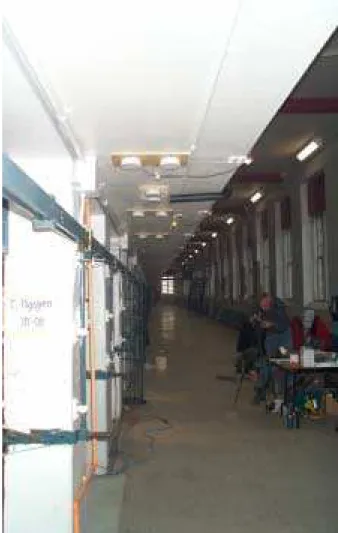
Figure 1 Two-storey cellblock and experimental cell on the ground floor
Figure 2 Plane view of experimental set-up
Figure 3 Four smoke detectors around the existing CSC detector in the cell
Figure 4 Ten smoke detectors in the corridor under the 2-floor walkway
Figure 5 Fuel packages of cotton mattress and polyurethane foam mattress
Figure 6 Fuel packages of clothing/parka and newspaper for flaming fires
Figure 7 Measurement devices and data acquisition system
Figures 8–21 Optical density of the smoke and response of the smoke detectors in various locations in Test 1 to Test 14.
Appendix A. Conversion chart of optical density and obscuration
Appendix B. Concentration-time profiles of carbon monoxide, carbon dioxide and oxygen Appendix C. Fax from Siemens on response of the CSC existing detector and the
1
EXPERIMENTS OF SMOKE DETECTOR RESPONSE IN PRISON FACILITIES
Joseph Z. Su, Bruce C. Taber, Don W. Carpenter
1.0 INTRODUCTION
The Correctional Service of Canada (CSC) has installed fire alarm systems throughout its prison facilities, including smoke detectors in individual cells as required by Article 3.2.4.11 of the National Building Code of Canada [1]. Since inmates frequently damage the smoke
detectors inside cells, CSC is considering relocating the smoke detectors outside the cells. CSC needs technical answers on whether this relocation increases fire detection time or risks due to fire.
The National Research Council of Canada (NRC) has conducted a research project, for CSC, to study the difference in response of smoke detectors installed inside and outside the cells. The objective of the project is to determine differences in fire detection time and the associated risk due to fires, relating to different detector locations.
This project required full-scale fire experiments to determine smoke detector response under a variety of conditions. NRC completed a series of fire detection experiments in a prison cell at Collins Bay Institution, with smoke detectors being installed at various locations in the cell, corridor and exhaust duct. The results of the experiments are documented in this report.
The project also involved an independent engineering analysis of operational and statistical data on reliability, maintenance, vandalism incidents, repairs and false alarms of smoke detection systems in correctional facilities. The engineering analysis and fire risk assessment was conducted and reported separately by Ken Richardson Fire Technologies Inc.
2.0 EXPERIMENTS
On January 28-30, 2002, NRC conducted 14 full-scale experiments at the Collins Bay Institution. The experiments are intended to evaluate the differences in response time for smoke detectors located in a cell compared to those located outside the cell envelope as part of an evaluation of risk to all occupants.
2.1 Experimental Cell
The experimental cellblock has 2 levels of cells with open-bar doors and a 2-storey high common hallway, as shown in Figure 1. A cell on the ground floor of the cellblock was used for fire detection experiments. The cell was 3.37 m long, 1.66 m wide, and 2.44 m high. The cell open-bar front was 1.21 m wide and 2.34 m high, with a 10 cm lintel. The top 30 cm of the open bars was covered with plywood to create additional lintel height. In about half of the
experiments, the open-bar front was completely covered using plywood to simulate a solid door cell.
At the back of the cell, there were a toilet and a washbasin. An existing sidewall sprinkler head (rated at 71°C or 160°F) and a duct opening (15 cm diameter) to the exhaust system were located on the back wall at a 2.1 m height.
2
2.2 Smoke Detectors
The cell had an existing CSC smoke detector on the ceiling, which was set to alarm at an obscuration of 3% per 304 mm (an optical density of 0.0435 per meter). This is the detector that CSC is considering moving. CSC also had a portable aspiration smoke detection device with a sampling tube installed in the cell, which displayed obscuration readout. This device had
4 alarm levels: alert at 0.025%/304 mm (3.6x10 -4/m), action at 0.0437%/304 mm (6.2x10 -4/m),
pre-fire alarm at 0.0625%/304 mm (8.9x10 -4/m), fire alarm at 3.0%/304 mm (0.0435/m).
In order to achieve experiment objectives in the determination of differences in fire detection time with different detector locations, multiple smoke detectors needed to be installed at various locations inside and outside the cell. This could not be done with the existing CSC fire alarm system. It was decided that CSC officials would arrange to monitor their existing fire alarm system and the aspiration detection device and that NRC would install a stand-alone detector system for the experiments.
A total of 7 photoelectric and 7 ionization smoke detectors (all powered by batteries) were installed inside and outside the experimental cell. Figure 2 shows a plan view of the locations of all smoke detectors installed. The existing CSC smoke detector in the cell (at mid-width, 2 m from the back wall) was protected by a metal cage (appears as a square in Figure 2). Two ionization detectors and 2 photoelectric detectors were installed in the cell around the existing CSC detector at the ceiling, as shown in Figure 3. Each of these 4 detectors had its edge 100mm away from the cage of the existing detector and centered on each side of the cage. Five ionization detectors and 5 photoelectric detectors were installed in the corridor outside the cell (under the 2nd-floor walkway), as shown in Figures 1 and 4. An ionization detector and a photoelectric detector formed a pair. One pair of detectors were parallel with and centered on the cell door, 38 cm from the wall. Four pairs of detectors were lined up
perpendicular with, and centered on, the four adjacent pillars between the cells. Each pair had one detector 25 cm from the pillar and the other detector 49 cm from the pillar. For each pair, the two detectors were spaced 100 mm from edge to edge.
There was no smoke detector installed in the exhaust duct from the cell. However, optical density in the duct was measured, providing data for determination of would-be activation time should a detector be located in the duct.
Two sprinkler heads with a temperature rating of 71°C (160°F) were mounted on the back wall beside the existing sprinkler head for possible "dry" operation during experiments. The existing automatic sprinkler system was de-actuated during the experiments.
2.3 Fuels and Fire Scenarios
Small and slow-growing fires (both flaming and smouldering) were used as test fires since these represent the most challenging situation for smoke detectors and the worst-case scenario as far as fire detection was concerned. Experimental fuel packages were prepared and pre-tested by NRC using cell content materials provided by CSC.
A cotton mattress and a polyurethane foam mattress were cut into 20 cm x 20 cm square pieces as fuel packages for smouldering fires. Each cotton mattress piece weighed
3
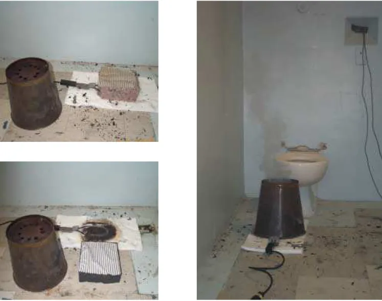
approximately 330 g and each foam mattress piece weighed approximately 290 g. As shown in Figure 5, smouldering fires were produced by putting the mattress fuel package on an
electrically-powered barbecue lighter, which lay on ceramic fibre batt insulation on the floor. A perforated metal bucket was used to cover the fuel and ignitor. The holes around the metal bucket controlled the amount of air available for combustion. Generated smoke came out from the holes on the top of the metal bucket.
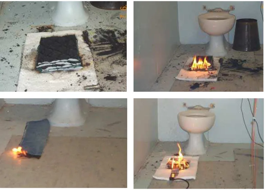
Pieces of clothing (parka) and newspaper were used for flaming fires, as shown in Figure 6. Clothing fuel packages were made using pieces of parka with denim material on top. One arrangement of the clothing packages was a strip of parka with the denim on top (12.7 cm long, 61 cm wide, 81 g). Another arrangement was 6 layers of parka and 6 layers of the denim stacked alternately over each other (20 cm long, 15 cm wide, 195 g). Flaming clothing fires were produced by pilot ignition using a torch. Ten full sheets of newspaper (weighed 190 g) were folded 8 times to a size of 15 cm x 15 cm. The newspaper package was put on a pre-heated barbecue lighter and ignited using a torch.
The fuel packages used in the experiments represent the most common materials first ignited in fire incidents in correctional occupancies. In order to provide the greatest challenges to the operation of the detectors located outside the cell envelope, fire locations were varied depending on whether the cell had an open or closed front, as shown in Figure 2. For experiments with the open front, the fire location was near the back wall since that was the greatest distance from the corridor detectors. For experiments with the closed front, the fire location was near the solid front door since that was the greatest distance from the exhaust duct. One experiment was also conducted using sweet grass as fuel in the open-bar cell.
2.4 Instrumentation
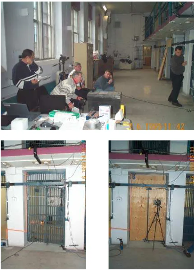
Various devices were used to measure smoke detector response, smoke obscuration (optical density), gas concentrations, temperatures and automatic sprinkler response, as shown in Figures 1–4 and 7. Experimental data was collected using a data acquisition system located in an adjacent cell. Data also included airflow in the exhaust duct of the cell and video records.
The response times of all detectors were determined by measuring the current draw through the batteries. Electric resistance of the sprinkler heads was also monitored to determine whether the sprinklers would operate.
Smoke optical density was measured as a function of time at 3 different locations in each experiment. The three optical density meters were of the aspiration type, drawing air samples from the ceiling near Detectors #12– #15 in the cell; from the location near Detectors #10– #11 in the corridor; and from the exhaust duct of the cell.
Temperatures in the cell were measured using a thermocouple tree. The thermocouple tree was installed near the centre of the cell beside Detector #15, with 5 thermocouples
distributed at heights of 0.6, 1.5, 1.8, 2.1 and 2.4 m above the floor.
CO, CO2 and O2 concentrations in the cell were measured using 4 gas analyzers. The
gas sampling ports were mounted on the thermocouple tree at heights of 1.5 and 2.4 m above the floor in the cell.
4
2.5 Experimental Procedure
All experiments were run with the normal building/cell ventilation system operational. The experimental procedure was as follows:
1. Verification of experiment layout, instrumentation and data acquisition; 2. t = 0 (time zero), starting data acquisition system;
3. t = 1 minute, igniting fuel;
4. Observation of smoke movement;
5. Ending the experiment.
The duration of each experiment was sufficient to enable determination of differences in detector response between in-cell and outside-cell units. The following represent the principles for experiment termination:
• For the open front experiments, response of in-cell detectors and corridor detectors directly
in front of cell door (Detectors #10– #15) plus an additional 5 min (or more) to determine if detectors located at junctions between cells would operate;
• For the closed front experiments, response of in-cell detectors (Detectors #12– #15) and the
optical density in duct exceeding the detector activation value; or
• A ceiling temperature of 50°C.
At the end of each experiment, NRC staff manually extinguished the fire by turning off the power supply to the barbecue lighter and carefully dropping the fuel package into a bucket of water or by using fire blankets.
CSC officials arranged with Siemens Building Technologies to monitor the existing fire alarm system and the aspiration smoke detection device during the experiments.
3.0 EXPERIMENTAL RESULTS
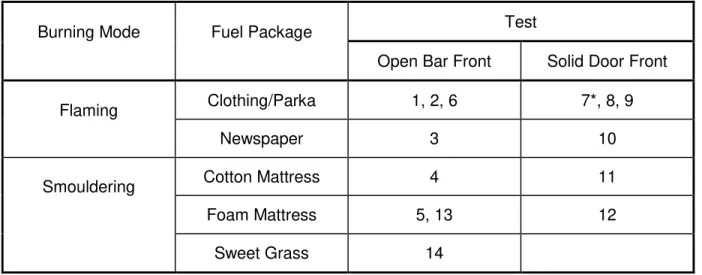
Table 1 shows the matrix of the fire detection experiments. The airflow in the exhaust duct was measured for both the open and closed front cells using a portable manometer. The air velocity at the centre of the exhaust duct was 3.4 m/s for the open-bar cell (measured during Test 4) and 2.7 m/s for the closed front cell (measured during Test 11).
Table 2 shows the maximum changes of temperature and gas concentrations in the cell during each experiment. The initial temperature in the cell was 24–26°C for all experiments. Since the test fires were small and grew slowly (in order to challenge the smoke detectors), the temperature rise in the cell at the ceiling was less than 4°C for all smouldering experiments and less than 21°C for all flaming experiments. In other words, the ceiling temperature in the cell was less than 30°C for all smouldering experiments and less than 46°C for all flaming
experiments. The dry sprinkler heads did not actuate during any experiments.
Table 2 also shows activated smoke detectors (with grey shading) during the fire
detection experiments and smoke optical densities (ODf) at the times of activation of Detectors
#12– #15 and Detectors #10– #11. In most cases when the cell had a solid door (closed), the smoke detectors outside the cell did not detect the fires inside the cell. When the cell had an open-bar door, the outside detectors detected the inside fires in most cases.
5
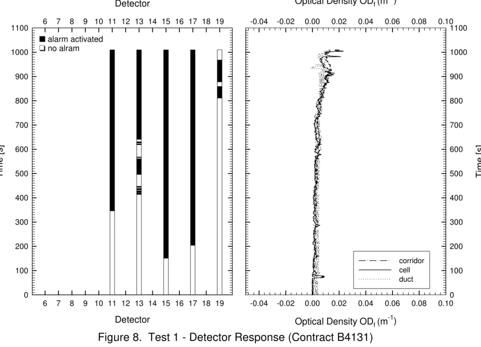
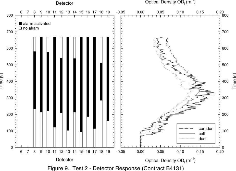
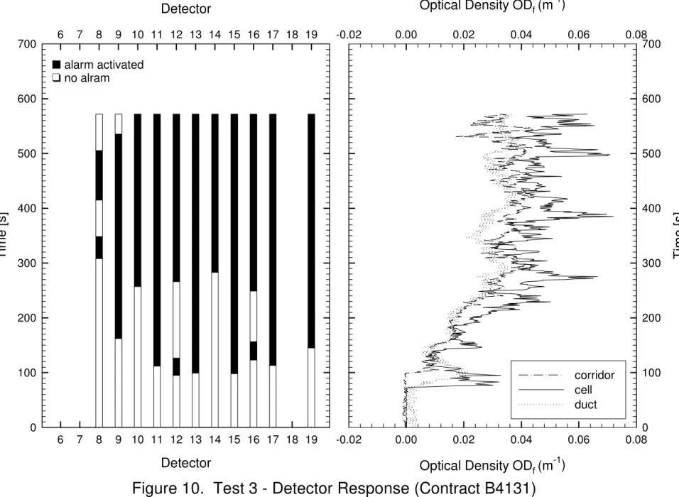
Figures 8–21 show optical density (ODf) of the smoke and response of the smoke
detectors in various locations (Note that ignition was at 60 s). The response times of the smoke detectors from ignition are shown in Table 3. For the flaming fires, the ionization detectors were almost always activated earlier than the photoelectric detectors at the same locations relative to the fires. For the smouldering fires, only in a little more than half of the cases, the photoelectric detectors were activated earlier than the ionization detectors at the same locations relative to the fires. Foam mattress smouldering took the longest time to detect under similar conditions.
The air movement in the hallway during the experiments, as indicated in Figure 2, had an impact on the response of the hallway smoke detectors. Because the air moved toward the east in the hallway, the detectors in the east side of the experimental cell generally activated earlier than those in the west side of the cell.
For the open-bar scenarios, the corridor detectors detected the test fires inside the cell within reasonable times. For the flaming fires in the open-bar cell, the first smoke alarm in the corridor occurred in less than 1 minute after the first smoke alarm in the cell. For the
smouldering fires in the open-bar cell, the first smoke alarm in the corridor occurred 1 to 4 minutes after the first smoke alarm in the cell. (All these are less than 60% longer than the in-cell detector response.)
From the experimental placement of the smoke detectors, 4 different placements of corridor detectors can be extracted for possible applications in CSC facilities. Placement A includes all the corridor detectors installed as shown in Figure 2. Placement B includes the corridor detectors installed in front of every pillar. Placement C includes only Detectors #6, #7, #16 and #17 installed in front of every other pillar. Placement D includes only Detectors #8, #9, #18 and #19 installed in front of every other pillar. Table 3 shows the time delay of the first smoke alarm in the corridor from the first smoke alarm in the cell for the 4 different corridor detector placements. There are no significant differences in the time delay for Placements A and B, indicating that the corridor detectors could be centered either on every cell or on every pillar with similar overall performance. Placements C and D are two arrangements for detector spacing at every other pillar. Favoured by the air movement in the corridor, Placement C responded to the in-cell fires with a similar time delay as for Placements A and B. Placement D would be the worse case for every-other-pillar spacing, and the time delay for this case should be used to determine whether detector spacing at every other pillar is acceptable.
No corridor detectors responded to the fires inside the closed cell in Tests 7, 8 and 12. Only a few corridor detectors initiated an alarm to the fires inside the closed cell in Tests 9, 10 and 11, with the earliest response time of 2 to 9 minutes (about 5 times) longer than the in-cell detector response.
Since the corridor smoke detectors could not reliably detect the test fires inside the cell when the cell had a solid door (closed), it is necessary to determine whether a duct detector is a viable option. Comparing the optical density profile in the duct with that in the cell (as shown in Figures 8–21) will allow determination of the time delay to reach a specific optical density in the duct. Table 4 shows the time delays of optical density in the duct at 7 different smoke
obscuration levels, compared to the times when optical density in the cell reached the same levels. The optical density values of 0.007, 0.014, 0.029, 0.044, 0.058, 0.073 and 0.088 per meter in the table are equivalent to the smoke obscuration levels of 0.5, 1, 2, 3, 4, 5 and 6% per foot, respectively. (Appendix A shows a conversion chart of optical density and obscuration.) The value of the obscuration per foot represents the percentage of projected light that cannot reach the distance of 1 foot. Under various experimental conditions, the delay times were less
6 than 1 minute in 60% of the cases and less than 2 minutes in 90% of the cases. At a 0.044/m optical density (3% per foot obscuration), the delay times in the duct were less than 2 minutes in all experiments. The delay time in the duct was usually longer for a higher optical density. The longest delay time was 6.5 minutes at the 0.088/m optical density (6% per foot obscuration) in Test 12. Should a smoke detector be installed in the duct, its response time to fires would depend not only on the fire conditions but also on its sensitivity setting (the lower the optical density, the higher the sensitivity).
The CO and CO2 concentrations listed in Table 2 are the maximum values in each
experiment. For all flaming fires, it took more than 4 minutes for CO and CO2 to reach these
maximum concentrations. For all smouldering fires, it took more than 5 minutes for CO and CO2
to reach these maximum concentrations. In most experiments, the time to reach the maximum
CO and CO2 concentrations was well behind the activation of the majority of the detectors.
(Complete concentration-time profiles are included in Appendix B.) The flaming fires produced
more CO2 while the smouldering fires produced more CO; the fires in the closed cell produced
higher CO and CO2 concentrations. Test 9 (clothing/parka flaming, closed cell) produced the
highest CO2 concentration of 0.6% and the lowest O2 concentration of 20.3% (as well as the
highest ceiling temperature of 46°C). Test 11 (cotton mattress smouldering, closed cell)
produced the highest CO concentration of 310-340 ppm. These CO and CO2 concentrations
produced under the experiment conditions are much lower than the limiting values that are immediately dangerous to life or health (IDLH). The IDLH value is 1500 ppm for CO and 5% for
CO2 [2].
The results of response from the existing fire alarm system and the aspiration smoke detection device monitored by CSC and Siemens are included in Appendix C. Except for Tests 2 and 4, these results are consistent with NRC's measurements.
Table 1 – Experiment Matrix for Smoke Detector Response
Test
Burning Mode Fuel Package
Open Bar Front Solid Door Front
Clothing/Parka 1, 2, 6 7*, 8, 9 Flaming Newspaper 3 10 Cotton Mattress 4 11 Foam Mattress 5, 13 12 Smouldering Sweet Grass 14
7
Table 2 – Detector Response and Maximum Changes of Temperature and Gas Concentrations (Jan. 2002)
Test 1 2 3 4 5 6 7* 8 9 10 11 12 13 14
Cell Door Open Open Open Open Open Open Closed Closed Closed Closed Closed Closed Open Open
Fuel Clothing Parka (strip) Clothing Parka (stack) News-paper Cotton Mattress Foam Mattress Clothing Parka (stack) Clothing Parka (strip) Clothing Parka (strip) Clothing Parka (stack) News-paper Cotton Mattress Foam Mattress Foam Mattress Sweet Grass Burning Mode
Flaming Flaming Flaming Smould-ering
Smould-ering
Flaming Flaming Flaming Flaming Flaming Smould-ering Smould-ering Smould-ering Smould-ering Temperature Max. (°C) 29.6 39.7 41.7 26.8 26.0 37.8 33.0 36.4 45.3 36.0 27.7 27.0 25.1 28.6 ceiling 20 15 90 240 150 20 40 65 70 160 340 190 150 15 CO (ppm) 1.5-m 30 10 50 150 70 20 50 60 60 130 310 160 70 10 ceiling 0.06 0.18 0.18 0.05 0.02 0.15 0.21 0.32 0.55 0.25 0.08 0.07 0.03 0.03 CO 2 % Rise 1.5-m 0.04 0.12 0.09 0.04 0.01 0.11 0.21 0.31 0.54 0.25 0.09 0.07 0.01 0.01 ceiling 0.07 0.20 0.19 0.05 0 0.15 0.20 0.35 0.61 0.25 0.10 0.07 0 0 O2 % Dr op 1.5-m 0.03 0.10 0.18 0.03 0 0.10 0.20 0.32 0.57 0.25 0.10 0.07 0 0 6 p 7 i 8 p 9 i 10 p 0.083 0.033 0.074 0.08 0.06 0.030 0.048 11 i 0.0025 0.025 0.010 0.070 0.01 0.03 0.010 0.025 0.048 12 p 0.095 0.040 0.050 0.03 0.104 0.046 0.07 0.026 0.090 0.062 0.032 13 i 0.001 0.048 0.018 0.050 0.08 0.018 0.005 0.002 0.02 0.014 0.055 0.091 0.090 0.004 14 p 0.10 0.050 0.020 0.048 0.11 0.046 0.08 0.020 0.060 0.060 0.049 15 i 0.001 0.045 0.018 0.098 0.03 0.015 0.001 0.003 0.02 0.016 0.045 0.016 0.034 0.004 16p 17 i 18 p De te c tor R e s pons e OD f (1 /m ) 19 i
Notes: (1) no additional lintel for Test 1, (2) initial temperature 24–26°C, (3) i for ionization, p for photoelectric, grey shading for activated detectors, (4) smoke optical density, ODf (1/m), only measured near Detectors #10, 11, 12, 13, 14 and 15, (5)* Test 7 - Fire located at the back of the cell.
8
Table 3 – Response Time of Detectors and Time Delay of Corridor Detectors Relative to Cell Detectors
Test 1 2 3 4 5 6 7 8 9 10 11 12 13 14
Cell Open Open Open Open Open Open Closed Closed Closed Closed Closed Closed Open Open
Fuel Clothing Parka (strip) Clothing Parka (stack) News-paper Cotton Mattress Foam Mattress Clothing Parka (stack) Clothing Parka (strip) Clothing Parka (strip) Clothing Parka (stack) News-paper Cotton Mattress Foam Mattress Foam Mattress Sweet Grass Burning Mode
Flaming Flaming Flaming Smould-ering
Smould-ering
Flaming Flaming Flaming Flaming Flaming Smould-ering Smould-ering Smould-ering Smould-ering 6 p 7 i 578 8 p 172 355 400 660 229 230 748 9 i 153 102 448 680 173 253 885 10 p 162 197 266 640 209 224 762 619 11 i 286 62 52 252 630 72 147 303 696 611 12 p 150 206 222 397 194 529 58 48 200 326 417 13 i 354 43 39 216 551 51 83 32 20 36 214 420 795 63 14 p 153 223 200 414 200 531 64 45 209 318 544 15 i 91 34 38 177 404 47 39 49 20 42 143 230 427 62 16p 127 189 260 691 171 240 771 611 17 i 144 54 53 253 717 74 164 234 620 18 p 225 710 342 De te c tor R e s pons e Time (s ) 19 i 751 102 85 535 728 145 A 53 20 14 75 226* 25 127 198 553 194 B 53 20 15 76 263 27 144 198 571* 194 C 53 20 15 76 294 27 144 198 571* 194 Time Delay (s) D 660 68 47 200* 263 98 172* 331 Notes:
(1) No additional lintel for Test 1; (2) Initial temperature of 24–26°C;
(3) Grey shading for activated detectors, i for ionization detector, p for photoelectric detector;
(4) Time Delay = time of the first corridor detector activation minus time of the first in-cell detector activation (* to ensure that the detectors involved are of the same type, this value is the time of the 1st corridor detector activation minus time of the 2nd in-cell detector activation) for
• Corridor Detector Placement A: containing Detectors #6, #7, #8, #9, #10, #11, #16, #17, #18, #19
• Corridor Detector Placement B: containing Detectors #6, #7, #8, #9, #16, #17, #18, #19 (in front of every pillar)
• Corridor Detector Placement C: containing Detectors #6, #7, #16, #17 (in front of every other pillar)
9
Table 4 – Time Delay (in seconds) of Duct Optical Density Relative to Cell Optical Density
Test 1 2 3 4 5 6 7 8 9 10 11 12 13
Cell Open Open Open Open Open Open Closed Closed Closed Closed Closed Closed Open
Fuel Clothing Parka (strip) Clothing Parka (stack) News-paper Cotton Mattress Foam Mattress Clothing Parka (stack) Clothing Parka (strip) Clothing Parka (strip) Clothing Parka (stack) News-paper Cotton Mattress Foam Mattress Foam Mattress Burning Mode
Flaming Flaming Flaming Smould-ering
Smould-ering
Flaming Flaming Flaming Flaming Flaming Smould-ering Smould-ering Smould-ering 0.007/m 110 12 10 29 -17 10 20 34 30 25 34 34 40 0.014/m 11 12 20 22 20 39 100 32 32 46 23 40 0.029/m 23 39 -32 42 35 105 34 45 51 70 103 0.044/m 55 -26 75 32 110 38 110 54 112 105 0.058/m 64 10 98 70 45 115 144 136 120 0.073/m 28 24 65 43 117 190 240 O p ti cal Den s it y 0.088/m 43 105 46 113 200 395
10
4.0 CONCLUSIONS
NRC completed a series of fire detection experiments on smoke detector response in the prison cell at the Collins Bay Institution to study the difference in response of smoke
detectors installed inside and outside the cells. NRC installed stand-alone detector arrays with 14 photoelectric and ionization smoke detectors (powered by batteries) at various locations inside and outside the experimental cell. All experiments were run with the normal building/cell ventilation system operational.
Small and slow-growing fires (both flaming and smouldering) were used as test fires since they would represent the most challenging situation for smoke detectors and the worst-case scenario as far as fire detection was concerned. Experimental fuel packages were prepared using the cell content materials, including cotton mattress, polyurethane foam mattress, clothing/parka and newspaper, which represented the most common materials first ignited in fire incidents in correctional occupancies.
Since the test fires were small, the ceiling temperature in the cell never exceeded 46°C
and, therefore, the automatic sprinklers were never actuated. The CO and CO2 concentrations
produced under the experiment conditions were much lower than the limiting values that are normally considered to represent an immediate danger to the life or health of a healthy adult.
At the same locations relative to the fires, the ionization detectors always responded to the flaming fires earlier than the photoelectric detectors while the response of the photoelectric detectors to the smouldering fires was not always earlier than the ionization detectors. Foam mattress smouldering took the longest time to detect.
For the open-bar scenarios, the corridor detectors detected the test fires inside the cell with the earliest response time less than 60% longer than the in-cell detector response. With the corridor detectors installed in front of every pillar, fires inside the open-bar cell are likely to be detected. However, should the corridor detectors be spaced at every other pillar, their response time to fires inside the cell could be double or triple that of the in-cell detectors.
In most cases where the cell had a solid door (closed), the smoke detectors outside the cell could not detect the fires inside the cell. In cases where the corridor detectors initiated an alarm to the fires inside the closed cell, the earliest response time was at least 5 times longer than the in-cell detector response.
The optical density measurement in the duct indicated that a duct detector works for the closed cell, provided that the duct detector be set at an appropriate sensitivity. In all
experiments, the time delay for the optical density to reach 0.044/m (3% per foot obscuration) in the duct was less than 2 minutes from the time when the optical density in the cell reached the same level. This delay time would be longer for a higher optical density. Should a smoke detector be installed in the duct, its response time to fires would depend not only on the fire conditions but also on its sensitivity setting (the lower the optical density, the higher the sensitivity, and the shorter the detection time).
With the results from these experiments and the analysis of statistical data on reliability, maintenance and vandalism incidents of smoke detection systems in correctional facilities, CSC can determine fire risk associated with different detector locations and propose a reliable, cost-effective alternative to in-cell smoke detectors.
11
5.0 ACKNOWLEDGEMENTS
This study was conducted as a joint research project between the National Research Council of Canada and the Correctional Service of Canada. NRC/IRC recognizes CSC's contribution in co-funding this project and providing the logistic support. In particular, the contribution of Mr. Randy Gaw, Chief Operational Fire Safety of CSC, in providing technical input and guidance and necessary assistance to NRC in designing and conducting the experiments is gratefully acknowledged.
6.0 REFERENCE
1. Canadian Commission on Building and Fire Codes, "National Building Code of Canada," National Research Council of Canada, Ottawa, 1995.
2. Occupational Safety and Health Administration, "OSHA Regulated Hazardous Substances," Noyes Data Corp., Park Ridge, 1990.
Figure 2. Plan view of experimental set-up (Contract B4131). P I S OD TC GS P P I I I P S S OD OD LEGEND
ionization smoke detector photoelectric smoke detector
sprinkler head
optical density measurements (at ceiling in cell and walkway) gas sampling at ceiling and 5' (CO, CO2, O2)
thermocouples (2', 5', 6', 7', ceiling)
GS TC
existing smoke detector
light fixture exhaust duct
edge of level 2 walkway
fire location for open cell
fire location for closed cell service corridor I P P I P I P I 7 6 8 9 11 10 17 16 18 19 15 13 12 14 OD
pillar pillar pillar pillar
air movement
N
↑↑↑↑
W
←
←→
←
←
→
→
→
E
↓↓↓↓
S
Figure 3. Four smoke detectors around the existing CSC detector in the cell (Contract B4131).
Figure 5. Fuel packages of cotton mattress and polyurethane foam mattress on an electrical barbecue lighter covered by a perforated metal bucket for smouldering fires (Contract B4131).
Figure 7. Measurement devices and data acquisition system (left - duct optical density measurement in the service corridor; middle - detector response, smoke density, gas and temperature measurements in the experiment cell; right - data acquisition system in an adjacent cell. Contract B4131).
Optical Density OD
f(m
-1)
-0.04 -0.02 0.00 0.02 0.04 0.06 0.08 0.10Optical Density OD
f(m
-1)
-0.04 -0.02 0.00 0.02 0.04 0.06 0.08 0.10Time [
s
]
0 100 200 300 400 500 600 700 800 900 1000 1100 corridor cell ductFigure 8. Test 1 - Detector Response (Contract B4131)
Detector
6 7 8 9 10 11 12 13 14 15 16 17 18 19Detector
6 7 8 9 10 11 12 13 14 15 16 17 18 19Time [
s
]
0 100 200 300 400 500 600 700 800 900 1000 1100 ■ alarm activated ❑ no alramOptical Density OD
f(m
-1)
-0.05 0.00 0.05 0.10 0.15 0.20Optical Density OD
f(m
-1)
-0.05 0.00 0.05 0.10 0.15 0.20Time [
s
]
0 100 200 300 400 500 600 700 800 corridor cell ductFigure 9. Test 2 - Detector Response (Contract B4131)
Detector
6 7 8 9 10 11 12 13 14 15 16 17 18 19Detector
6 7 8 9 10 11 12 13 14 15 16 17 18 19Time [
s
]
0 100 200 300 400 500 600 700 800 ■ alarm activated ❑ no alramOptical Density OD
f(m
-1)
-0.02 0.00 0.02 0.04 0.06 0.08Optical Density OD
f(m
-1)
-0.02 0.00 0.02 0.04 0.06 0.08Time [
s
]
0 100 200 300 400 500 600 700 corridor cell ductFigure 10. Test 3 - Detector Response (Contract B4131)
Detector
6 7 8 9 10 11 12 13 14 15 16 17 18 19Detector
6 7 8 9 10 11 12 13 14 15 16 17 18 19Time [
s
]
0 100 200 300 400 500 600 700 ■ alarm activated ❑ no alramOptical Density OD
f(m
-1)
-0.02 0.00 0.02 0.04 0.06 0.08 0.10 0.12 0.14 0.16Optical Density OD
f(m
-1)
-0.02 0.00 0.02 0.04 0.06 0.08 0.10 0.12 0.14 0.16Time [
s
]
0 100 200 300 400 500 600 700 800 900 1000 corridor cell ductFigure 11. Test 4 - Detector Response (Contract B4131)
Detector
6 7 8 9 10 11 12 13 14 15 16 17 18 19Detector
6 7 8 9 10 11 12 13 14 15 16 17 18 19Time [
s
]
0 100 200 300 400 500 600 700 800 900 1000 ■ alarm activated ❑ no alramOptical Density OD
f(m
-1)
-0.02 0.00 0.02 0.04 0.06 0.08 0.10 0.12Optical Density OD
f(m
-1)
-0.02 0.00 0.02 0.04 0.06 0.08 0.10 0.12Time [
s
]
0 100 200 300 400 500 600 700 800 900 1000 corridor cell ductFigure 12. Test 5 - Detector Response (Contract B4131)
Detector
6 7 8 9 10 11 12 13 14 15 16 17 18 19Detector
6 7 8 9 10 11 12 13 14 15 16 17 18 19Time [
s
]
0 100 200 300 400 500 600 700 800 900 1000 ■ alarm activated ❑ no alramOptical Density OD
f(m
-1)
-0.02 0.00 0.02 0.04 0.06 0.08 0.10 0.12 0.14 0.16 0.18Optical Density OD
f(m
-1)
-0.02 0.00 0.02 0.04 0.06 0.08 0.10 0.12 0.14 0.16 0.18Time [
s
]
0 100 200 300 400 500 600 corridor cell ductFigure 13. Test 6 - Detector Response (Contract B4131)
Detector
6 7 8 9 10 11 12 13 14 15 16 17 18 19Detector
6 7 8 9 10 11 12 13 14 15 16 17 18 19Time [
s
]
0 100 200 300 400 500 600 ■ alarm activated ❑ no alramOptical Density OD
f(m
-1)
-0.04 -0.02 0.00 0.02 0.04 0.06 0.08 0.10Optical Density OD
f(m
-1)
-0.04 -0.02 0.00 0.02 0.04 0.06 0.08 0.10Time [
s
]
0 100 200 300 400 500 600 700 800 corridor vs time cell vs time duct vs timeFigure 14. Test 7 - Detector Response (Contract B4131)
Detector
6 7 8 9 10 11 12 13 14 15 16 17 18 19Detector
6 7 8 9 10 11 12 13 14 15 16 17 18 19Time [
s
]
0 100 200 300 400 500 600 700 800 ■ alarm activated ❑ no alramOptical Density OD
f(m
-1)
-0.02 0.00 0.02 0.04 0.06 0.08Optical Density OD
f(m
-1)
-0.02 0.00 0.02 0.04 0.06 0.08Time [
s
]
0 100 200 300 400 500 600 700 corridor cell ductFigure 15. Test 8 - Detector Response (Contract B4131)
Detector
6 7 8 9 10 11 12 13 14 15 16 17 18 19Detector
6 7 8 9 10 11 12 13 14 15 16 17 18 19Time [
s
]
0 100 200 300 400 500 600 700 ■ alarm activated ❑ no alramOptical Density OD
f(m
-1)
-0.1 0.0 0.1 0.2 0.3 0.4 0.5 0.6Optical Density OD
f(m
-1)
-0.1 0.0 0.1 0.2 0.3 0.4 0.5 0.6Time [
s
]
0 100 200 300 400 500 corridor cell ductFigure 16. Test 9 - Detector Response (Contract B4131)
Detector
6 7 8 9 10 11 12 13 14 15 16 17 18 19Detector
6 7 8 9 10 11 12 13 14 15 16 17 18 19Time [
s
]
0 100 200 300 400 500 ■ alarm activated ❑ no alramOptical Density OD
f(m
-1)
-0.02 0.00 0.02 0.04 0.06 0.08 0.10 0.12 0.14 0.16Optical Density OD
f(m
-1)
-0.02 0.00 0.02 0.04 0.06 0.08 0.10 0.12 0.14 0.16Time [
s
]
0 100 200 300 400 500 600 corridor cell ductFigure 17. Test 10 - Detector Response (Contract B4131)
Detector
6 7 8 9 10 11 12 13 14 15 16 17 18 19Detector
6 7 8 9 10 11 12 13 14 15 16 17 18 19Time [
s
]
0 100 200 300 400 500 600 ■ alarm activated ❑ no alramOptical Density OD
f(m
-1)
-0.05 0.00 0.05 0.10 0.15 0.20 0.25Optical Density OD
f(m
-1)
-0.05 0.00 0.05 0.10 0.15 0.20 0.25Time [
s
]
0 100 200 300 400 500 600 700 800 900 1000 corridor cell ductFigure 18. Test 11 - Detector Response (Contract B4131)
Detector
6 7 8 9 10 11 12 13 14 15 16 17 18 19Detector
6 7 8 9 10 11 12 13 14 15 16 17 18 19Time [
s
]
0 100 200 300 400 500 600 700 800 900 1000 ■ alarm activated ❑ no alramOptical Density OD
f(m
-1)
-0.02 0.00 0.02 0.04 0.06 0.08 0.10 0.12 0.14 0.16Optical Density OD
f(m
-1)
-0.02 0.00 0.02 0.04 0.06 0.08 0.10 0.12 0.14 0.16Time [
s
]
0 100 200 300 400 500 600 700 800 900 1000 corridor cell ductFigure 19. Test 12 - Detector Response (Contract B4131)
Detector
6 7 8 9 10 11 12 13 14 15 16 17 18 19Detector
6 7 8 9 10 11 12 13 14 15 16 17 18 19Time [
s
]
0 100 200 300 400 500 600 700 800 900 1000 ■ alarm activated ❑ no alramOptical Density OD
f(m
-1)
-0.02 0.00 0.02 0.04 0.06 0.08 0.10 0.12Optical Density OD
f(m
-1)
-0.02 0.00 0.02 0.04 0.06 0.08 0.10 0.12Time [
s
]
0 100 200 300 400 500 600 700 800 900 1000 1100 corridor cell ductFigure 20. Test 13 - Detector Response (Contract B4131)
Detector
6 7 8 9 10 11 12 13 14 15 16 17 18 19Detector
6 7 8 9 10 11 12 13 14 15 16 17 18 19Time [
s
]
0 100 200 300 400 500 600 700 800 900 1000 1100 ■ alarm activated ❑ no alramOptical Density OD
f(m
-1)
-0.04 -0.02 0.00 0.02 0.04 0.06 0.08 0.10Optical Density OD
f(m
-1)
-0.04 -0.02 0.00 0.02 0.04 0.06 0.08 0.10Time [
s
]
0 100 200 300 corridor cell ductFigure 21. Test 14 - Detector Response (Contract B4131)
Detector
6 7 8 9 10 11 12 13 14 15 16 17 18 19Detector
6 7 8 9 10 11 12 13 14 15 16 17 18 19Time [
s
]
0 100 200 300 ■ alarm activated ❑ no alramOptical Density, OD
f(1/m)
0.00 0.05 0.10 0.15 0.20 0.25Ob
scuration, O
u(
%
/
30
4 mm)
0 1 2 3 4 5 6 7 8 9 10 11 12 13 14 15 Ou ODf 0.0250 3.5719x10⁻⁴ 0.0437 6.2443x10⁻⁴ 0.0625 8.9315x10⁻⁴ 0.1400 2.0014x10⁻³ 1.0500 0.0151 2.0000 0.0289 2.4000 0.0347 2.5000 0.0362 2.6000 0.0376 2.7000 0.0391 3.0000 0.0435 3.1000 0.0450 4.8000 0.0703 5.0000 0.0733Appendix B
B4131 Test 1 - CO
Time [s]
0
200
400
600
800
1000
1200
CO [%]
-0.004
-0.002
0.000
0.002
0.004
time vs CO% ceiling
B4131 Test 1 - CO
2
Time [s]
0
200
400
600
800
1000
1200
CO
2
[%]
0.00
0.02
0.04
0.06
0.08
0.10
time vs CO2% ceiling
time vs CO2% mid
B4131 Test 1 - O
2
Time [s]
0
200
400
600
800
1000
1200
O
2
[%]
20.0
20.5
21.0
21.5
22.0
time vs O2% ceiling
time vs O2% mid
B4131 Test 2 - CO
Time [s]
0
200
400
600
800
CO [%]
-0.004
-0.002
0.000
0.002
0.004
time vs CO% ceiling
B4131 Test 2 - CO
2
Time [s]
0
200
400
600
800
CO
2
[%]
0.00
0.02
0.04
0.06
0.08
0.10
0.12
0.14
0.16
0.18
0.20
0.22
time vs CO2% ceiling
time vs CO2% mid
B4131 Test 2 - O
2
Time [s]
0
200
400
600
800
O
2
[%]
20.0
20.5
21.0
21.5
22.0
time vs O2% ceiling
time vs O2% mid
B4131 Test 3 - CO
Time [s]
0
100
200
300
400
500
600
700
CO [%]
-0.002
0.000
0.002
0.004
0.006
0.008
0.010
time vs CO% ceiling
time vs CO% mid
B4131 Test 3 - CO
2
Time [s]
0
100
200
300
400
500
600
700
CO
2
[%]
0.00
0.05
0.10
0.15
0.20
0.25
time vs CO2% ceiling
time vs CO2% mid
B4131 Test 3 - O
2
Time [s]
0
100
200
300
400
500
600
700
O
2
[%]
20.0
20.5
21.0
21.5
22.0
time vs O2% ceiling
time vs O2% mid
B4131 Test 4 - CO
Time [s]
0
200
400
600
800
1000
CO [%]
-0.005
0.000
0.005
0.010
0.015
0.020
0.025
time vs CO% ceiling
time vs CO% mid
B4131 Test 4 - CO
2
Time [s]
0
200
400
600
800
1000
CO
2
[%]
0.01
0.02
0.03
0.04
0.05
0.06
0.07
0.08
time vs CO2% ceiling
time vs CO2% mid
B4131 Test 4 - O
2
Time [s]
0
200
400
600
800
1000
O
2
[%]
20.0
20.5
21.0
21.5
22.0
time vs O2% ceiling
time vs O2% mid
B4131 Test 5 - CO
Time [s]
0
100
200
300
400
500
600
700
CO [%]
-0.005
0.000
0.005
0.010
0.015
0.020
time vs CO% ceiling
time vs CO% mid
B4131 Test 5 - CO
2
Time [s]
0
100
200
300
400
500
600
700
CO
2
[%]
0.00
0.01
0.02
0.03
0.04
0.05
0.06
time vs CO2% ceiling
time vs CO2% mid
B4131 Test 5 - O
2
Time [s]
0
100
200
300
400
500
600
700
O
2
[%]
20.0
20.5
21.0
21.5
22.0
time vs O2% ceiling
time vs O2% mid
B4131 Test 6 - CO
Time [s]
0
100
200
300
400
500
600
CO [%]
-0.002
0.000
0.002
0.004
0.006
0.008
0.010
time vs CO% ceiling
time vs CO% mid
B4131 Test 6 - CO
2
Time [s]
0
100
200
300
400
500
600
CO
2
[%]
0.00
0.02
0.04
0.06
0.08
0.10
0.12
0.14
0.16
0.18
0.20
time vs CO2% ceiling
time vs CO2% mid
B4131 Test 6 - O
2
Time [s]
0
100
200
300
400
500
600
O
2
[%]
20.0
20.5
21.0
21.5
22.0
time vs O2% ceiling
time vs O2% mid
B4131 Test 7 - CO
Time [s]
0
200
400
600
800
CO [%]
-0.002
0.000
0.002
0.004
0.006
0.008
0.010
time vs CO% ceiling
time vs CO% mid
B4131 Test 7 - CO
2
Time [s]
0
200
400
600
800
CO
2
[%]
0.00
0.05
0.10
0.15
0.20
0.25
time vs CO2% ceiling
time vs CO2% mid
B4131 Test 7 - O
2
Time [s]
0
200
400
600
800
O
2
[%]
20.0
20.5
21.0
21.5
22.0
time vs O2% ceiling
time vs O2% mid
B4131 Test 8 - CO
Time [s]
0
100
200
300
400
500
600
700
CO [%]
-0.002
0.000
0.002
0.004
0.006
0.008
0.010
time vs CO% ceiling
time vs CO% mid
B4131 Test 8 - CO
2
Time [s]
0
100
200
300
400
500
600
700
CO
2
[%]
0.0
0.1
0.2
0.3
0.4
time vs CO2% ceiling
time vs CO2% mid
B4131 Test 8 - O
2
Time [s]
0
100
200
300
400
500
600
700
O
2
[%]
20.0
20.5
21.0
21.5
22.0
time vs O2% ceiling
time vs O2% mid
B4131 Test 9 - CO
Time [s]
0
100
200
300
400
500
CO [%]
-0.002
0.000
0.002
0.004
0.006
0.008
time vs CO% ceiling
time vs CO% mid
B4131 Test 9 - CO
2
Time [s]
0
100
200
300
400
500
CO
2
[%]
0.0
0.1
0.2
0.3
0.4
0.5
0.6
0.7
time vs CO2% ceiling
time vs CO2% mid
B4131 Test 9 - O
2
Time [s]
0
100
200
300
400
500
O
2
[%]
20.2
20.4
20.6
20.8
21.0
21.2
time vs O2% ceiling
time vs O2% mid
B4131 Test 10 - CO
Time [s]
0
100
200
300
400
500
600
CO [%]
-0.005
0.000
0.005
0.010
0.015
0.020
time vs CO% ceiling
time vs CO% mid
B4131 Test 10 - CO
2
Time [s]
0
100
200
300
400
500
600
CO
2
[%]
0.00
0.05
0.10
0.15
0.20
0.25
0.30
time vs CO2% ceiling
time vs CO2% mid
B4131 Test 10 - O
2
Time [s]
0
100
200
300
400
500
600
O
2
[%]
20.0
20.5
21.0
21.5
22.0
time vs O2% ceiling
time vs O2% mid
B4131 Test 11 - CO
Time [s]
0
200
400
600
800
1000
CO [%]
-0.01
0.00
0.01
0.02
0.03
0.04
time vs CO% ceiling
time vs CO% mid
B4131 Test 11 - CO
2
Time [s]
0
200
400
600
800
1000
CO
2
[%]
0.00
0.02
0.04
0.06
0.08
0.10
0.12
time vs CO2% ceiling
time vs CO2% mid
B4131 Test 11 - O
2
Time [s]
0
200
400
600
800
1000
O
2
[%]
20.0
20.5
21.0
21.5
22.0
time vs O2% ceiling
time vs O2% mid
B4131 Test 12 - CO
Time [s]
0
200
400
600
800
1000
CO [%]
-0.005
0.000
0.005
0.010
0.015
0.020
0.025
time vs CO% ceiling
time vs CO% mid
B4131 Test 12 - CO
2
Time [s]
0
200
400
600
800
1000
CO
2
[%]
0.00
0.02
0.04
0.06
0.08
0.10
time vs CO2% ceiling
time vs CO2% mid
B4131 Test 12 - O
2
Time [s]
0
200
400
600
800
1000
O
2
[%]
20.0
20.5
21.0
21.5
22.0
time vs O2% ceiling
time vs O2% mid
B4131 Test 13 - CO
Time [s]
0
200
400
600
800
1000
1200
CO [%]
-0.004
-0.002
0.000
0.002
0.004
0.006
0.008
0.010
0.012
0.014
0.016
time vs CO% ceiling
time vs CO% mid
B4131 Test 13 - CO
2
Time [s]
0
200
400
600
800
1000
1200
CO
2
[%]
0.00
0.02
0.04
0.06
0.08
0.10
time vs CO2% ceiling
time vs CO2% mid
B4131 Test 13 - O
2
Time [s]
0
200
400
600
800
1000
1200
O
2
[%]
20.0
20.5
21.0
21.5
22.0
time vs O2% ceiling
time vs O2% mid
B4131 Test 14 - CO
Time [s]
0
50
100
150
200
250
300
CO [%]
-0.002
-0.001
0.000
0.001
0.002
time vs CO% ceiling
time vs CO% mid
B4131 Test 14 - CO
2
Time [s]
0
50
100
150
200
250
300
CO
2
[%]
0.00
0.01
0.02
0.03
0.04
0.05
0.06
time vs CO2% ceiling
time vs CO2% mid
B4131 Test 14 - O
2
Time [s]
0
50
100
150
200
250
300
O
2
[%]
20.0
20.5
21.0
21.5
22.0
time vs O2% ceiling
time vs O2% mid
Appendix C
Fax from Siemens on response of the CSC existing detector and the aspiration smoke detection device