HAL Id: hal-01619338
https://hal.uca.fr/hal-01619338
Submitted on 19 Oct 2017
HAL is a multi-disciplinary open access
archive for the deposit and dissemination of
sci-entific research documents, whether they are
pub-lished or not. The documents may come from
teaching and research institutions in France or
abroad, or from public or private research centers.
L’archive ouverte pluridisciplinaire HAL, est
destinée au dépôt et à la diffusion de documents
scientifiques de niveau recherche, publiés ou non,
émanant des établissements d’enseignement et de
recherche français ou étrangers, des laboratoires
publics ou privés.
Multi-layer Ontologies for Integrated 3D Shape
Segmentation and Annotation
Thomas Dietenbeck, Fakhri Torkhani, Ahlem Othmani, Marco Attene,
Jean-Marie Favreau
To cite this version:
Thomas Dietenbeck, Fakhri Torkhani, Ahlem Othmani, Marco Attene, Jean-Marie Favreau.
Multi-layer Ontologies for Integrated 3D Shape Segmentation and Annotation. Advances in Knowledge
Discovery and Management, 2016, �10.1007/978-3-319-45763-5_10�. �hal-01619338�
segmentation and annotation
Thomas Dietenbeck, Fakhri Torkhani, Ahlem Othmani, Marco Attene, Jean-Marie Favreau
Abstract Mesh segmentation and semantic annotation are used as preprocessing steps for many applications, including shape retrieval, mesh abstraction, and adap-tive simplification. In current practice, these two steps are done sequentially: a purely geometrical analysis is employed to extract the relevant parts, and then these parts are annotated. We introduce an original framework where annotation and seg-mentation are performed simultaneously, so that each of the two steps can take ad-vantage of the other. Inspired by existing methods used in image processing, we employ an expert’s knowledge of the context to drive the process while minimiz-ing the use of geometric analysis. For each specific context a multi-layer ontology can be designed on top of a basic knowledge layer which conceptualizes 3D object features from the point of view of their geometry, topology, and possible attributes. Each feature is associated with an elementary algorithm for its detection. An expert can define the upper layers of the ontology to conceptualize a specific domain with-out the need to reconsider the elementary algorithms. This approach has a twofold advantage: on one hand it allows to leverage domain knowledge from experts even if they have limited or no skills in geometry processing and computer
program-Thomas Dietenbeck
Sorbonne Universit´es, UPMC Univ Paris 06, INSERM UMRS 1146, CNRS UMR 7371, Labora-toire d’Imagerie Biom´edicale, F-75013, Paris, France, e-mail: [email protected] Fakhri Torkhani
Clermont Universit´e, Universit´e d’Auvergne, ISIT, BP10448, F-63000 Clermont-Ferrand, CNRS, UMR6284, BP10448, F-63000 Clermont-Ferrand, e-mail: [email protected]
Ahlem Othmani
Clermont Universit´e, Universit´e d’Auvergne, ISIT, BP10448, F-63000 Clermont-Ferrand, CNRS, UMR6284, BP10448, F-63000 Clermont-Ferrand, e-mail: [email protected]
Marco Attene
CNR-IMATI, Italy, e-mail: [email protected] Jean-Marie Favreau
Clermont Universit´e, Universit´e d’Auvergne, ISIT, BP10448, F-63000 Clermont-Ferrand, CNRS, UMR6284, BP10448, F-63000 Clermont-Ferrand, e-mail: [email protected]
2 Authors Suppressed Due to Excessive Length
ming; on the other hand, it provides a solid ground to be easily extended in different contexts with a limited effort.
1 Introduction
During the last two decades, adding a semantic description to a scene has been an emerging problematic in the data mining and mesh processing communities. One of the main goals is to be able to extract an abstract description of the manipulated data, using some semantic descriptors. Bridging the gap between raw data and semantic concepts is a very complicated task which usually requires a good knowledge of the specific applicative domain the systems are working on. This link between the expert knowledge and the raw data can be achieved either by using learning techniques or by designing a deterministic system which expresses the knowledge of the expert in a language of computer science.
By assuming that an object belongs to a specific semantic class, advanced mesh segmentation techniques can tag both the whole object and its subparts with se-mantic terms that describe the shape, the structure and sometimes even the func-tionality of the object [Laga et al., 2013]. When the overall context in known, the identification of an object from its shape may rely on a two-step approach: the ob-ject’s relevant parts are first recognized through shape segmentation and then la-belled using the concepts available in a specific formalization of the context (e.g. an ontology). Some of these approaches [Hudelot et al., 2008, Hassan et al., 2010, Fouquier et al., 2012] are able to exploit the partial semantic description of the scene and to adjust their behaviour to the context. Unfortunately, the algorithms and pro-cedures used in the aforementioned approaches are very specific to their applicative domain and are hardcoded within their implementation.
In this article, we describe an original framework for mesh segmentation that pushes up the semantic approach, thus creating a bridge bewteen an expert knowl-edge description and the segmentation algorithms. This framework allows an expert in a specific area to formally describe his own ontology, without the need to have any particular skill in geometry processing or shape analysis. The formalized do-main description is then used by the system to automatically recognize objects and their features within that domain.
The genericity of our approach is enabled by a multi-layer ontology which for-mally describes the expert knowledge. The first layer corresponds to the basic prop-erties of any object, such as shapes and structures. The upper layers are specific to each application domain, and describe the functionalities and possible configura-tions of the objects in this domain. The segmentation and the annotation mechanism is hidden behind the concepts of the first layer, which are associated to specific geometric algorithms.
In section 2 an overview of the existing methods for part-based annotation of 3D shapes is presented. Section 3 introduces our framework for semantics-driven mesh segmentation and annotation; here we describe how to model the expert’s
knowl-edge, how our synthetic catalog of segmentation algorithms is composed, and how our expert system works. The elementary algorithms that compute the basic shape features are described in Section 4. Section 5 presents some experimental results to illustrate the relevance and feasibility of our approach. Section 6 is reserved for the discussion of possible extensions of this work and future improvements to overcome its current limitations.
2 Related Work
The design of enhanced vision systems can take a significant advantage from semantic formalizations such as ontologies. The ontology paradigm in informa-tion science represents one of the most diffused tools to make people from var-ious backgrounds work together [Seifert et al., 2011]. Ontology-based interfaces are a key component of ergonomic adaptive computer systems [Seifert et al., 2011, Maillot and Thonnat, 2008], especially in biological/clinical fields [Othmani et al., 2010, Hassan et al., 2010, Fouquier et al., 2012] for which concepts and standards are constantly shifting. Furthermore, reasoning capabilities embedded in the logical framework on which ontology softwares are built up can be exploited to improve the performances of existing computer vision systems. Even though still brittle and limited, reasoning inferences out of visual data may enhance the vision sys-tem experience [Othmani et al., 2010] as well. In the Computer Graphics commu-nity the use of semantics has been a key for significant achievements in appli-cations such as anatomy [Hassan et al., 2010], product design in e-manufacturing [Attene et al., 2009] and robotics [Albrecht et al., 2011, Gurau and N¨uchter, 2013]. In [Camossi et al., 2007], a system to assist a user in the retrieval and the seman-tic annotation of 3D models of objects in different applications is presented. The ontology provides a representation of the knowledge needed to encode an object’s shape, its functionality and its behavior. Then, the annotation and the retrieval are performed based on the functional and the behavior characteristics of the 3D model. In [Attene et al., 2009], the ontology is used to characterize and to annotate the segmented parts of a mesh using a system called “ShapeAnnotator”. To this aim, the ontology is loaded according to the input mesh type and the user can link segments to relevant concepts expressed by the ontology. While the anno-tation of the mesh parts is done by a simple link within the “ShapeAnnotator”, [Gurau and N¨uchter, 2013] and [Shi et al., 2012] proposed to feed an ontology with a set of user-defined rules (e.g. geometric properties of objects, spatial relationships) and the final annotation is created according to them.
In [Hassan et al., 2010], an ontology including an approximation of the geomet-ric shape of some anatomical organs is used to guide the mesh segmentation. The parameters needed to segment the input mesh are provided by the ontology. For the case of semantic classification, an ontology is also used in [Albrecht et al., 2011] to “idealize” SLAM-generated 3D point cloud maps. The ontology is used to gen-erate hypotheses of possible object locations and initial poses estimation, and the
4 Authors Suppressed Due to Excessive Length
final result is a hybrid semantic map where all the identified objects are replaced by their corresponding CAD models. Recently, [Feng and Pan, 2013] proposed a uni-fied framework which bridges semantics and mesh processing. The mesh is divided into a fixed number of parts corresponding to the number of concepts in the ontol-ogy. The parts are then annotated based on some rules defined in the ontology and specific to the context (e.g. in a human body the head and a limb are very dissimilar). In [Symonova et al., 2006], the authors focus their work on mesh annotation us-ing an already segmented object. The regions to annotate are defined by connected components in the shape, and the low level labelling is done by using the distribution of local geometric features. The high level annotation is then produced by using con-nectivity rules and geometrical primitive constraints. Our present work can be seen as a generalization of this original work for the annotation part, while we introduce specific and robust algorithms for the low level labelling, and a complete framework that extends the possibilities introduced by Symonova et al. In our proposal, each new relation or low level label with the corresponding elementary algorithm will be handled automatically by our expert system.
3 Proposed Method
Segmenting an object based on its geometry and associating semantic concepts to each part are non trivial problems, both requiring a very specific process-ing. Previous works [Hudelot et al., 2008, Attene et al., 2009, Hassan et al., 2010, Fouquier et al., 2012] on this topic are more and more going in the direction of mix-ing the two problems, in order to help the segmentation usmix-ing the already extracted semantics, and by extracting the semantics from the partial segmentations.
The framework we present in this section addresses the same goal by focusing on the separation between the segmentation algorithms and semantic reasoning. Thanks to such a separation, addressing a new applicative domain will only require the user to design the corresponding ontology, without code modification. All the necessary geometric machinery and the low-level semantic rules, indeed, are already encoded in the original core of the framework. In the next section, we propose complemen-tary benefits of this approach, and we discuss in the last section several possible extensions.
In a first part, we describe our multi-layer ontology paradigm and how the ex-pert knowledge on a specific domain is implemented on top of elementary concepts. Then we introduce our framework to tackle the problem of semantics-driven mesh segmentation using the defined ontology paradigm. Finally, we give the specifica-tions of the elementary algorithms involved in the segmentation process.
3.1 Terminology
Our work focuses on mesh processing, with the aim to achieve both segmentation and semantic labelling. In the remainder, we call object a 3D shape defined by a triangular mesh. A region of the mesh is a connected subset of its triangles. A seg-mentation is a subdivision of the mesh into a collection of regions called segments. A region is not necessarily a segment. Finally, we use the term concept in the usual way to describe an abstract semantic class.
3.2 Expert Knowledge Description
The idea behind our expert knowledge system is to mimic our visual mechanism of object recognition. Indeed the expert knowledge description follows a “whole-to-part” analysis, where the object of interest is modelled in the top layer of our ontology and is first decomposed into regions according to a criterion (shape, tex-ture, . . . ). A region can potentially be further divided until elementary subparts are obtained corresponding to the intermediate layers of our ontology. Features of these parts as well as relations between them are described using semantic concepts gath-ered in the last layer of the ontology. Putting these informations together along with user-defined rules allow us to label each part ultimately leading to the recognition of the object.
A segmentation and semantic labelling process implies that the algorithmic part is able to identify and label regions with specific properties, such as geometrical properties (e.g. sphere, cube, vertical region), color or texture properties (e.g. color uniformity, reflectance, texture patterns), but also properties linked to the relative position and configuration of subparts (e.g. parallel regions,A is up wrt B, A is betweenB and C ). We note however that all these properties cannot be formalized in the same way. Indeed, some of them extend the knowledge on a given part of the mesh by detailing its features (e.g. geometry, color, orientation), while other link severalregions together (e.g. through topology, distance) thus describing the overall structure of the object.
3.2.1 Features and unary properties
A first group of properties characterizing an object are based on the aspect of its parts (e.g. geometry, color, etc.). These properties extend the knowledge on a given part and thus link it to a feature concept (e.g.A is a cube, is red, etc.). Since each property only involve one part of an object, we will refer them as unary property.
More specifically, in the ontology, each unary property corresponds to an object property where the domain is the object parts. The range concept corresponds to the features of interest (e.g. shape, orientation, color) which are further specialized into elementary semantic concepts corresponding to the possible value of the object
6 Authors Suppressed Due to Excessive Length
hasShape
Cube
(a)
Cube
isReferenceRegion UpFrom isTargetRegion (b)
Fig. 1: Examples of unary and n-ary property.A and B correspond to regions of the object.
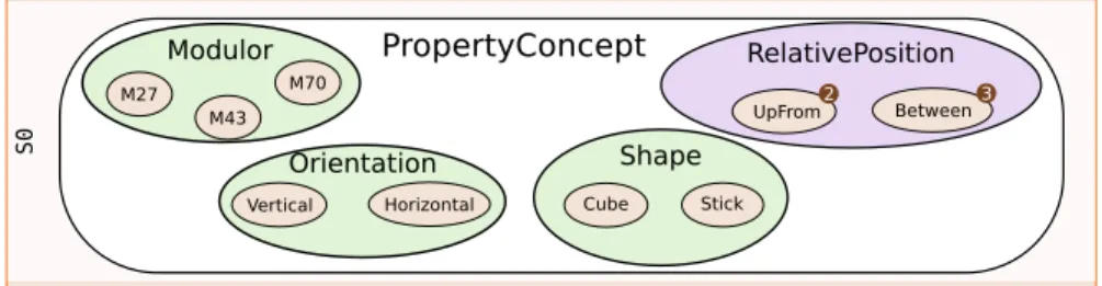
Fig. 2: A subpart of the elementary semantic concepts of the core ontology. The number beside some concepts indicate that they link several regions together (e.g. UpFrom relates 2 regionsA and B).
property. An example of unary property is given in Fig. 1-(a) and range concepts and their associated elementary semantic concepts are illustrated in Fig. 2 (green ellipses).
3.2.2 Topology and n-ary properties
The second group of properties allows to link object’s parts together thus giving the overall structure of the object. This kind of properties combines 2 or more parts along with a topological concept (e.g.A and B are close, B is above A , etc.) and will thus be refered to as n-ary property.
However, ontologies cannot directly model n-ary properties and we thus model them following the “N-ary Relation” pattern described in [Dodds and Davis, 2012]1.
More specifically, a concept (e.g. position, distance) is created for the relation and is also specialized into elementary semantic concepts (e.g. position → UpFrom, Be-tween, etc.). Each object part corresponds to a ressource of the relation and is related to it through two distinct object properties. The first one “isTargetRegion” allows to define the region we wish to position in space, while the other “isReferenceRegion” states the fixed region used to orientate the space (i.e. to define the semantic).
Considering the example given in Fig. 1-(b), the n-ary property can be read asB (the target) is aboveA (the reference). The violet ellipse in Fig. 2 illustrates a range of two n-ary relations where the number on the right of each elementary semantic concepts indicates the number of object parts related through this concepts (e.g. 2 parts for UpFrom).
S0 S1 S2 Top o log y Geometry Color Furniture
Seat Back Support
(a)
(b)
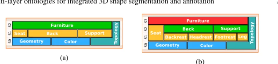
Fig. 3: Example of multi-layer ontologies for Furnitures. Note how a more detailed expert knowledge description of the same domain can be achieved by simply adding a layer, e.g. for the concepts of Back or Support in the case of Furnitures.
S0 S 1 S 2 S3 Facade DoorRoof Wall Window Vege tationRoad Street Color Geometry Top o log y (a) S0 S 1 S 2 S3 S4 Color Geometry Top o log y Facade Door Windowsill Window Shutter Window Wall Roof Vege tationRoad Street (b)
Fig. 4: Example of multi-layer ontologies for Streets.
3.2.3 Multi-layer Ontology
In order to model our “whole-to-part” recognition mechanism, we structured our ontology in layers. The first layer (called S0, blue blocks in Fig. 3 and Fig. 4) is part
of the core of our framework. It contains the feature and topological concepts and associated unary and n-ary concepts described in the previous sections.
The S0layer is enriched for each applicative context with specific semantic
con-cepts which are grouped into two (or more) layers: one layer called S1 (yellow
blocks in Fig. 3 and Fig. 4), using only references to concepts from the S0layer,
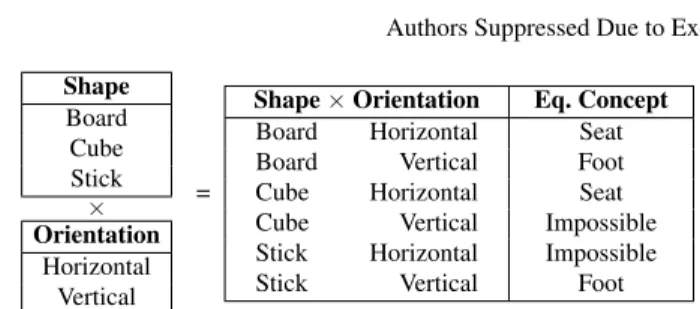
de-scribes all the object configurations that can be combinatorially built, i.e the result of a cartesian product between elementary semantic concepts. Fig. 5 illustrates an example of such a cartesian product for 2 unary properties (Shape and Orientation). The supplementary layers (S2, . . . , Sn, green, red and purple blocks in Fig. 3 and
Fig. 4) describe the combination rules to populate a complete scene. The top layer of the ontology corresponds to the list of objects one wish to label. The advantage of this representation is that it is very easy to fit the level of details in the description of objects required by the application. Indeed if supplementary informations are required for an object part, it only requires to add a layer in the ontology. Similarly if only a rough description of the part is sufficient, one may remove the unnecessary layer.
To illustrate this motivation, consider the example given in Fig. 3. In Fig. 3-(a), a furniture is obtained by combining a seat, a back and a support, all of which being described using S0concepts. For instance, the back of a furniture is modelled in a
rough manner as being a vertical board possibly linked to vertical sticks (e.g. for a chair) and above the seat. However this may not be sufficient to distinguish between all the furnitures: namely a difference between a chair and an armchair resides in
8 Authors Suppressed Due to Excessive Length Shape Board Cube Stick × Orientation Horizontal Vertical =
Shape × Orientation Eq. Concept
Board Horizontal Seat
Board Vertical Foot
Cube Horizontal Seat
Cube Vertical Impossible
Stick Horizontal Impossible
Stick Vertical Foot
Fig. 5: Cartesian product between two range of elementary semantic concepts, and the corresponding equivalent concepts.
the fact that armchair may have a headrest. To add this supplementary knowledge, a supplementary layer is introduced (see Fig. 3-(b)) describing the back of a furniture as a backrest and a possible headrest above it.
3.2.4 Linking two Layers: Equivalent Concepts
In addition to the semantic concepts of the application domain, another important expert knowledge consists in how the concepts are linked with each other. This can be expressed as a set of equivalent concepts of the Sn layer describing
pos-sible or impospos-sible combinations of concepts of the Sn−1 layer. The work of the
expert is thus strongly simplified since he can describe not only positive rules (i.e. valid/plausible configurations), but also negative rules (i.e. impossible/incompatible combinations). For example, in the furniture ontology a chair leg can be described as a stick shape with a vertical orientation; on the other hand, the combination of a headrest without backrest is an incompatible configuration.
In practice, incompatible configurations are specialized in specific concepts, one for each incompatibility type. This specialization allows to perform some reasoning and classification on partially annotated individuals.
Once these equivalent concepts are given by the expert, they are used in two ways: either to build a decision tree (which will be detailled in Section 3.3) or to suggest a correction of the segmentation. Indeed, during the segmentation / annota-tion process, incompatible configuraannota-tions might appear due to either a segmentaannota-tion error or a missing equivalent concept. In this case, the reasoner can be asked for the cause of the inconsistency which is then presented to the user for correction. The main advantages of this approach is that it allows us to ask the user to correct errors only in the regions that caused an incompatibility instead of having to explore the whole mesh / labelling.
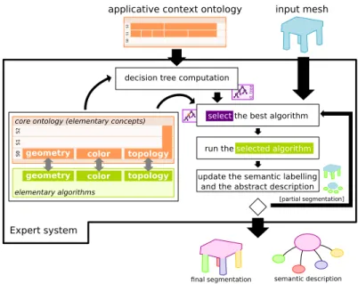
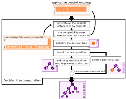
Fig. 6: Overview of the proposed method applied on the furniture domain.
3.3 Expert System
In this section, we describe how the expert knowledge is used in our framework to efficiently segment and annotate an object. Fig. 6 gives an overview on this frame-work.
3.3.1 Generation of a Decision Tree
One of the advantages of our approach is that it gives the possibility to easily com-pute a tree containing the order of the questions to ask to reach the solution in the most efficient way. To build this decision tree, we first use the equivalent concepts of each layer to build the set of possible configurations. For each layer and starting at the first layer S0, the Cartesian product between all the properties of the layer is
performed (Fig. 5, Shape × Orientation column). The reasoner is then used to clas-sify the instances in equivalent concepts and incompatible candidates are removed (Fig. 5, Eq. Concept column). The remaining ones are then used in the above layer as semantic concepts in the Cartesian product to compute the new list of possible configurations.
Once the set of all possible configurations Ω is created, the idea is to split it according to the concept maximizing a criterion C. The choice of this concept gives us the question to ask and thus a node of the tree. For each possible answer, we then get the corresponding subset and look for the next concept maximizing C. This
10 Authors Suppressed Due to Excessive Length
Fig. 7: Offline decision-tree generation from the ontology of the application domain.
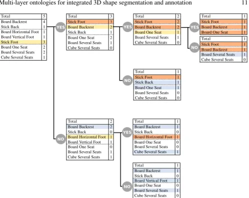
operation is iterated until only one possibility is left in each subset. In the resulting tree, the root thus corresponds to Ω and stores the first question to ask, each leaf is a possible configuration and intermediary nodes are subsets of Ω storing the next question to ask. Note that this step can be performed only once and offline in order to speed up the process. This procedure is illustrated in Fig. 7 and an example of complete decision tree is given in Fig. 8 where the criterion used to split Ω is the dichotomy. The reader will also find an illustration on the applicative context of furnitures in section 5.1.1.
3.3.2 Optimized Segmentation using the Decision Tree
The first inline step of our expert system is to browse the decision tree: starting from the root, the system gets the question to ask and runs the associated elementary al-gorithm on the input object (see section 3.4 for the formulation and classification of these algorithms). The system then selects the child node corresponding to the algorithm’s result and the process iterates until a leaf of the tree is reached, meaning that the semantics associated to the object is known as only one possible configura-tion remains. A complete run of the inline process is given in secconfigura-tion 5.1.2 on the applicative context of furnitures.
In some cases, the expert system might reach a leaf before every part of the mesh is segmented or annotated (because some concepts might be inferred from the presence / absence of others). Some supplementary algorithms can then be run
YES
NO
Total 5 Board Backrest 4 Stick Back 1 Board Horizontal Foot 1 Board Vertical Foot 1 Stick Foot 3 Board One Seat 2 Board Several Seats 2 Cube Several Seats 1
Total 3 Board Backrest 2 Stick Back 1 Stick Foot 3 Board One Seat 2 Board Several Seats 1 Cube Several Seats 0
YES
NO
Total 1 Stick Back 1 Stick Foot 1 Board One Seat 1 Board Several Seats 0 Cube Several Seats 0 Total 2 Board Backrest 2 Stick Foot 2 Board One Seat 1 Board Several Seats 1 Cube Several Seats 0
YES
NO
Total 1 Board Backrest 1 Stick Foot 1 Board One Seat 1 Total 1 Board Backrest 1 Stick Foot 1 Board Several Seats 1 Cube Several Seats 0
Total 2 Board Backrest 2 Stick Back 0 Board Horizontal Foot 1 Board Vertical Foot 1 Board One Seat 0 Board Several Seats 1 Cube Several Seats 1
YES
NO
Total 1 Board Backrest 1 Stick Back 0 Board Horizontal Foot 1 Board One Seat 0 Board Several Seats 0 Cube Several Seats 1 Total 1 Board Backrest 1 Stick Back 0 Board Vertical Foot 1 Board One Seat 0 Board Several Seats 1 Cube Several Seats 0
Fig. 8: Illustration of the generation of the decision tree. The dashed lines group the elementary semantic concepts into a common property. Yellow: best question at a given node of the tree; Orange: asserted concepts through previous question; Blue: inferred concepts (because only one possibility left in the property)
on the mesh to confirm the global semantics and annotate the missing parts. This can again be done very efficiently by questionning the reasoner, which will give the expert system the missing concepts and thus the elementary algorithm to run.
3.4 Mesh Processing Formalisation
In this work, the core idea about the mesh processing part is to split the processing into elementary algorithms, each dedicated to the evaluation of one of the elemen-tary semantic concepts. To produce a synthetic catalog of the algorithms, however, the signature of each algorithm must be defined both by the concept it handles and by the desired specific task.
12 Authors Suppressed Due to Excessive Length
3.4.1 Semantic Type Signatures of Algorithms
Each elementary algorithm is involved in the segmentation and labelling process and can realize the following tasks:
• looking for a given concept and segmenting the mesh in corresponding subparts, • checking if an existing region satisfies or not a given concept,
• focusing on relative positions or links of several regions.
Since a region can be described by more than one concept (for example, a part can be both a “stick” and “vertical”), and since our goal is to have as many elemen-tary algorithms as possible, we deduce that there also exist algorithms that do not split the given region, but only increase the knowledge on this region. Finally, and because we want to deal with concepts that are not necessarily involving a single re-gion, we need to distinguish functions associated to unary properties, and functions associated to n-ary properties.
The following synthetic catalog is a proposal to identify each segmentation algo-rithm in the context of semantic labelling:
• semantical questions starting with find all (SF), with unary concepts (e.g. find all rectangles in regionA ),
• semantical questions starting with is it a (SI), with unary concepts (e.g. isB a flat region),
• topological questions (T), identifying n-ary relations between regions (e.g. areB andC connected),
• topological questions starting with find all (TF), using an n-ary relation and 1 to n− 1 regions, to find regions satisfying the relation wrt the input regions (e.g. find all regions connected to the regionB; find all regions between the regions B and C ).
Each algorithm takes as input one or more regions of the original object and returns a set of regions, each enriched by a semantic description generated by the function, plus a score in [0; 1] to illustrate the matching between this region and the associated concept. This first synthetic catalog of possible semantic type signatures covers all the useful algorithms for mesh segmentation using semantic description, as illustrated in section 3.3 and thereafter.
3.4.2 Minimal Set of Algorithms
Designing one algorithm of each type for each property can be very complex, in particular for concepts that are not very precisely defined. In particular, if a SI algorithm can be designed for each property, the SF algorithms are taking on them the complicated task of segmentation. Depending of the accuracy of the concept, it can be very complicated to design a corresponding SF algorithm.
Fortunately, the expert system described in the next paragraph is able to deal with a minimal set of algorithms that does not contain all the SF algorithms. Whenever a
new find all algorithm is required, the system restricts itself to the existing ones. The only mandatory constraint is that all the regions of the objects must be segmentable. We describe in section 4 an example of such a minimal set.
For n-ary properties we can proceed in a similar manner. T algorithms must be implemented for each n-ary properties. On the other hand, TF algorithms can be implemented, or only deduced using a combination of T and SF algorithms.
3.4.3 Region Description
The algorithms of our framework use regions of meshes as input, and can also pro-duce regions in case of “find all” algorithm. A classical way to describe regions consists on using existing vertices, edges and triangles without refining the data structure. Moreover, a segmentation process consists in splitting a given object into subregions. Using triangles as elementary parts of a surface mesh is then a straight-forward choice.
However, we know that the result of a segmentation step is sometimes uncer-tain, in particular on the segment borders. To handle this uncertainty, we choose to use in this work fuzzy maps to describe regions. A fuzzy map is defined as a func-tion that associates to each triangle of the mesh a membership value in [0; 1]. This formulation gives a way to deal with contradictory segmentations such as partially overlapping regions.
4 Details of the Elementary Algorithms
We defined a minimal set of algorithms corresponding to the S0concepts described
in figure 12 left.
4.1 Fuzzy Membership
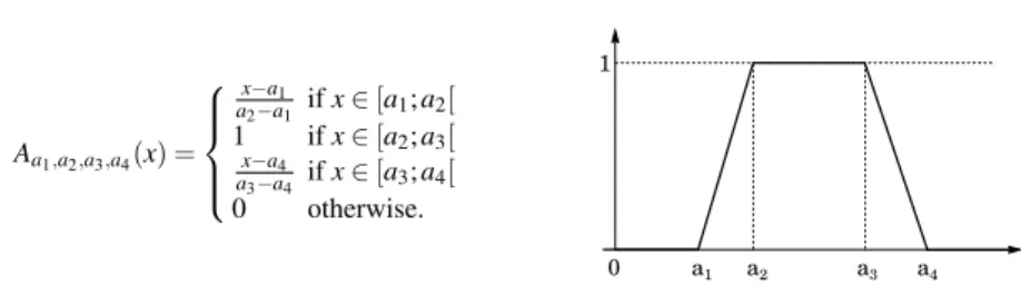
Each of the defined algorithms is able to express its result using a score value in [0; 1] to illustrate the matching between the manipulated region and the corre-sponding concept. In this work, we choose to use trapezoidal membership tions [Klir and Yuan, 1995] to compute this score. A trapezoidal membership func-tion is defined by 4 real parameters a1≤ a2≤ a3≤ a4as described in Fig. 9.
The defined algorithms are described in the next section, with a common use of the trapezoidal membership functions as fuzzy rules: we first measure a geometric property on the manipulated region (such as an angle with the vertical axis, or a ratio between scales), then we use a specific fuzzy rule to obtain the final score.
14 Authors Suppressed Due to Excessive Length Aa1,a2,a3,a4(x) = x−a1 a2−a1 if x ∈ [a1; a2[ 1 if x ∈ [a2; a3[ x−a4 a3−a4 if x ∈ [a3; a4[ 0 otherwise.
Fig. 9: Trapezoidal membership function Aa1,a2,a3,a4
We can notice here that more complex membership functions can be used for this description, but trapezoidal functions has been identified as rich enough to drive our algorithms in the applicative context described in section 5.
4.2 Elementary Algorithms
For each of these concepts we designed an “is-a” algorithm. “Find-all” algorithms have been defined only for the shape properties, since this property domain is han-dling all the possible regions we want to address. This partial implementation of the “find-all” algorithms is motivated in section 3.4.2, and we focus our work on the shape properties due to their efficiency to define strict boundaries.
4.2.1 “is a” Algorithms
Each of the elementary properties has been translated into an “is a” algorithm. As described in section 3.4, the input of these algorithms is defined by a fuzzy region Fon a meshM .
Using elementary geometric algorithms, we designed “is a” algorithms to iden-tify shape properties (cube, stick, board), vertical and horizontal orientations, com-pactness of a shape, and position properties wrt the vertical axis. The details of these algorithms presented in section 6.2 are related with the extraction of an oriented bounding box, and some fuzzy rules to quantify the examined properties.
4.2.2 “Find all” Algorithms
The quality of the final segmentation and annotation is mainly related to the quality of the “find all” algorithms: in our framework, the location of the region and the accuracy of their boundaries depend only on these algorithms. We focus our imple-mentation work on the algorithm able to detect boards, i.e. able to detect regions made up of two parallel planar regions and possibly lateral surfaces. Fig. 10 give an example of board that illustrate possible specific configurations: the lateral surfaces
a
Fig. 10: A board is composed of two parallel planar regions (pink) with lateral sur-faces (blue), possibly with holes due to connections with other regions (leg, back).
a b
Fig. 11: a: hierarchical primitive fitting [Attene et al., 2006] on a bench. b: what we expected.
may not be perfectly orthogonal to the planes, and the shape may contain holes both in the planes and the lateral surfaces, due to the junction with other regions.
Mesh segmentation based on primitives is a classical problem with many existing approaches. These methods are usually focusing on a few number of primitives, such as spheres, planes and cylinders. These techniques are able to segment each of the faces of a board, and possibly the lateral surfaces if the shape is not too complicated. Hierarchical techniques [Attene et al., 2006] are able to handle more complex shapes by providing a multi-level segmentation. Fig. 11-a illustrates the inability of these approaches to handle board shapes: a lateral surface of the seat has been selected as a part of the back rest.
Alternative approaches are using first a primitive fitting procedure, then combine the detected primitives to generate thin-plates [Geng et al., 2010].
We have designed an alternative approach that performs the fitting of two parallel primitives at the same time, then defines the shape by adding the lateral surfaces. This approach avoid the over segmentation of planar regions without opposite parts, and could possibly be extended to non straight boards, by introducing a parametric model for parallel bended surfaces.
16 Authors Suppressed Due to Excessive Length
Section 6.4 gives the details of our approach, which uses first an estimation of the local thickness of the object, then uses a growing process from the thin points to find the two sides of each region. Finally, a last step is applied to localize the side triangles.
5 Experiments on Furnitures Segmentation and Annotation
The experiments have been done on furniture segmentation and annotation, using basic shapes relevant to this domain (see Fig. 12 right). We implemented the expert system detailed in section 3.3 using Java and the OWL API, and designed our prototype such that the purely mesh manipulations are written in C++, using CGAL (see section 4). The connection between these two parts is done using a client/server paradigm via sockets. The complete software has been released as an Open-Source software under GPL2.
5.1 Applicative Context and Results of the Annotation
The specific context of furnitures is addressed by designing a dedicated ontology (see Fig. 12 left) using Prot´eg´e3and the reasoner HermiT on top of a simplified version of the elementary concepts introduced in sections 3.2.1 and 3.2.2. These ontologies has been released with our source code under GPL2.
5.1.1 Decision Tree Generation
The decision tree associated to this ontology is generated as described in section 3.3 where the criterion C was chosen to be the dichotomy, i.e. we look for concepts allowing to split the set into two subset of same size.
5.1.2 Expert Segmentation Processing
Once the decision tree is generated, we can run our expert segmentation system on meshes. Fig. 13 gives the list of questions that are computed in order to segment and recognize the first bench in Fig. 12. The other images in Fig. 12 illustrate the segmentation and annotation process using the same expert ontology with various meshes.
2Software and ontologies of our work are available online: http://odds.jmfavreau.info/ 3Prot´eg´e, an ontology editor: http://protege.stanford.edu/
Fig. 12: Ontology and meshes used for our experiments on furniture segmentation and annotation. Right: result of the segmentation and annotation on 5 objects from the furniture domain. Result of the annotation: orange ⇒ backrest, blue ⇒ seat, other colors ⇒ feet.
R0 R1 R2 R3 R4 1. SF StickShape in R0: false 2. SF BoardShape in R0 • R1: true (0.999) • R2: true (0.999) • R3: true (1) • R4: true (0.999) 3. SI HorizontalOrientation in R1: true (1) 4. SI HorizontalOrientation in R2: false (0) 5. SI HorizontalOrientation in R3: false (0) 6. SI HorizontalOrientation in R4: false (0) 7. SI DownPosition in R1: false (0) 8. SI CompactProperty in R2: false (0.082) 9. SI M27 in R2: false (0) 10. SI DownPosition in R2: false (0) 11. SI CompactProperty in R3: true (0.999) 12. SI M27 in R3: false (0) 13. SI DownPosition in R3: true (1) 14. SI CompactProperty in R4: true (0.999) 15. SI M27 in R4: false (0) 16. SI DownPosition in R4: true (1) 17. SI CompactProperty in R1: false (0.062)
Fig. 13: List of the elementary algorithms and corresponding answers generated by our expert system to segment and annotate a bench mesh. SF: semantic find all, SI: semantic is it a.
Fig. 14 illustrates the consequence of a rule (Section 3.2.4) that detects a con-figuration that is not part of the possible furnitures described in the expert system: a board is identified in the foot part, and the object is classified as incompatible (concept FootIncompatibleFurnitures).
18 Authors Suppressed Due to Excessive Length 1. SF StickShape in R0 • R1: true (1) • R2: true (0.999) • R3: true (1) • R4: true (1) • R5: true (1) • R6: true (1) 2. SI VerticalOrientation in R1: true (1) 3. SI VerticalOrientation in R2: true (1) 4. SI VerticalOrientation in R3: true (1) 5. SI VerticalOrientation in R4: true (1) 6. SI VerticalOrientation in R5: true (1) 7. SI VerticalOrientation in R6: true (1) 8. SI DownPosition in R1: true (1) 9. SI DownPosition in R2: true (1) 10. SI DownPosition in R3: true (1) 11. SI DownPosition in R4: true (1) 12. SI DownPosition in R5: false (0) 13. SI DownPosition in R6: false (0) 14. SI CompactProperty in R5: false (0) 15. SI M27 in R5: false (0) 16. SI CompactProperty in R6: false (0) 17. SI M27 in R6: false (0) 18. SF BoardShape inR0 - { R1, R2, R3, R4, R5, R6 } • R7: true (0.999) • R8: true (0.999) • R9: true (1) 19. SI VerticalOrientation in R7: false (0) 20. SI VerticalOrientation in R8: false (0) 21. SI VerticalOrientation in R9: true (1) 22. SI UpPosition in R9: true (0.858) 23. SI CompactProperty in R7: true (0.999) 24. SI M43 in R7: false (0) 25. SI CompactProperty in R8: true (0.999) 26. SI M43 in R8: true (0.956) 27. SI CentralPosition in R8: true (0.699)
Fig. 14: Example of a mesh which is not valid wrt the expert knowl-edge, the corresponding list of elementary algorithms and answers pro-duced by our expert system, and the final diagnosis: ChairFurniture, FootIncompatibleFurnitures.
5.2 Evaluation of the Approach
In this section, we first give time information on the experiments we performed, providing computation times for each of the main stages of our pipeline. In the next section, we present some comparison facts with existing work. Finally, we present some high level complexity elements considering the usage of the ontology.
5.2.1 Computation Time
The presented computations has been done on an Intel i-7 2.00GHz with 8 Go of RAM, using the software prototype presented below. The decision tree generation for the furnitures context illustrated in figure 8 takes 11.45 seconds from the loading of the ontology to the saving of the results.
Once this offline process is done, each mesh can be processed as illustrated in figure 13 using our software prototype. Table 1 gives some computation times of the key steps for several furniture meshes.
Mesh #subparts #triangles Find all (s) Is a (ms) Total (s)
bench 4 36 0.188 0.259 2.270 bench2 6 52 0.216 0.319 2.712 chair 6 52 0.231 0.326 3.096 chair2 8 82 0.276 0.509 2.376 couch 6 52 0.291 0.264 2.295 curved-bench 29 2542 1.038 6.167 6.743 strange-object2 9 100 0.337 0.695 2.502
Table 1: Computation time of the expert system for segmentation and annotation of several meshes.
Noise 0% 0.5% 1%
Our method 3.40s 5.25s 7.01s
Fitting primitives 24s 6s 6s
Table 2: Computation time of the segmentation process on a 75 520 triangles mesh with different levels of noise, with our method and with [Attene et al., 2006].
The computation time of the “find all” steps is obviously strongly related to the number of triangles of the mesh, due to the computation technics introduced in section 4.2.2. This fact can be seen in Table 1.
The planarity of the shapes is also a criterion that modifies the computation time. To illustrate this fact, we applied a multiscale random noise on an complex original shape (Figure 16) composed of 75 520 triangles gathered in 4 board-like regions. We used a root mean square deviation of 0.5 percent (respectivly 1 percent) of the object’s bounding box diagonal length. Table 2 illustrate this property.
It gives the computation time of the ‘‘find all” segmentation process that seg-ments the shape into two board regions, one stick region and one cube region.
We also used the same computer to run the implementation of [Attene et al., 2006] provided by the author. This existing work is not exactly analogous, since it provides a complete hierarchical representation of fitted primitives, and do not gives a way to obtain a solution to the board finding problem. However, it gives a good intuition about the state of the art in primitive detection.
The computation times given in Table 2 are illustrating the fact that the two meth-ods share the same order of magnitude.
5.2.2 Comparison with Existing Work
Comparing our current work with existing methods can be separated into two sides: segmentation and annotation.
In our current implementation, the segmentation part is mainly driven by the “find all” board described in the previous section. As we underline at the begin-ning of this section, the closest approach is the thin-plates mesh model splitting approach [Geng et al., 2010]. This reference work does not contain any complex-ity or computation time evaluation, but the fact that we fit simultaneously the two planes of our boards necessarily reduces the complexity of our approach, since our model avoids the segmentation of single planes that are not accompanied by another parallel surface. For example, a thin board with a profile composed of n segments will be composed of n + 2 planes. A classical approach will detect n + 2 planes, while the proposed method will detect only a pair of planes. The n other planes will be part of the detected border, without subdivision. Moreover, our method is able to handle thin-plates with complex boundary shapes (as illustrated in Fig. 16), that are not handled by classical fitting primitive approaches.
20 Authors Suppressed Due to Excessive Length
Object #subparts
S. then I. Naive S&I Our method preprocessing - -# SF # SI # SF # SI # SF # SI bench 1 4 0 28 3 20 2 15 bench 2 6 0 42 3 30 3 14 couch 6 0 42 3 30 2 13 chair 1 6 0 42 3 30 2 14 chair 2 8 0 56 3 40 2 22
Table 3: Number of segmentation steps for a complete annotation and segmentation.
The other “is a” algorithms are not strongly novel. The novelty consists here on the categorisation and review described in section 6.3: to the best of our knowledge, no other work provides such a comprehensive analysis.
The annotation part of our framework consists both of the “is a” algorithms that we mentioned above and the expert system described in section 3.3. This work can be compared with existing works such as [Feng and Pan, 2013] or [Attene et al., 2009], but in these two approaches the complexity of the annotation is handled by either the user or context-specific algorithms. As a result, we are not aware of any other significant existing work which we could compare to.
5.2.3 On the Usage of the Ontology
In this section, we present a short comparison of our framework with two alternative approaches, in case the ontology is not exploited to drive the expert system. Experi-mental results of this comparison are summarized in Tab. 3. The first column, which is entitled S. then I. corresponds to an approach where a first segmentation pre-processing is done to split regions, then each region is labeled using the semantic concepts. The second column which is entitled Naive S&I corresponds to an ap-proach where the initial split is produced using segmentation algorithms dedicated to shape detection, then by using the complementary algorithms to fully identify the regions. The last column corresponds to our approach. For each method, we de-tailed the number of semantic “find all” (SF) and semantic “is it a” (SI) algorithms required to segment and annotate the 5 objects shown in Fig. 12 right.
We choose to distinguish the 2 kinds of algorithms, because the complexity of each algorithm family is significantly different: a SF algorithm will require to browse all the given regions (possibly the whole mesh), and will have to extract the subparts from it. In comparison, a SI algorithm will only have to validate or not a feature on a given region. Minimizing the number of SF runs is thus the main goal of a segmentation and annotation process.
For each region of an object, the expert of the ontology uses 5 range concepts (shape, position, orientation, modulor, compactness) that implies 12 elementary se-mantic concepts. The number of SI algorithms in the S. then I. has been estimated counting for each subregion of the mesh one SI per elementary semantic concept (minus 1 per range concept that can be deduced). The Naive S&I consist in running
the SF algorithms dedicated to shapes, then run all the other SI algorithms on each of the segmented regions (all minus one per concept range). The number of SF and SIof our method comes from the trace of the experimental runs (see an example in Fig. 13).
We first compare our work to a S. then I. approach, where a segmentation pre-processing is applied before the annotation. We cannot quantitatively compare this approach with ours, but since we use the expert knowledge to reduce the number of SFalgorithms in our approach, we can deduce that our SF computations are almost equivalently expensive as the preprocessing stage of the S. then I. approach4. The number of SI algorithms is also strongly reduced with our approach.
The second approach considered for comparison is a Naive S&I approach, where all the SF algorithms of the shape range are run, then all the complementary SI al-gorithms are run. The number of SF alal-gorithms is at least preserved by our approach and sometimes reduced, and many SI runs are saved thanks to our framework.
These first results motivate the relevance of our method with respect to the ex-isting approaches: mixing segmentation and annotation steps is a good approach to reduce the theoretical complexity of the global algorithm, by reducing the number of segmentation and identification algorithms to run. Moreover, it gives a global framework to extend the existing approaches to more complex contexts.
6 Conclusion and Future Work
In this paper, we presented a new framework for efficient segmentation and anno-tation of meshes. It is composed of two blocks: a multi-layer ontology gathering the semantics and a segmentation part allowing to detect elementary geometrical, chromatical and topological concepts. The main advantage of our method is that it separates the domain knowledge with the processing allowing an expert to segment and annotate an object without knowledge in image or mesh processing. Another advantage is that using the expert knowledge, we are able to build a decision tree to perform an efficient search amongst the set of possible objects while being able to suggest segmentation and annotation corrections to the user if an impossible config-uration is reached.
6.1 Limitations
We can identify two kind of limitations in this work. First, the elementary concepts and the associated algorithms which we designed are mainly focused on manufac-tured shapes. In other words, the first layer of our ontology does not effectively con-ceptualize other objects such as organic shapes. Furthermore, we assume that the 4The best strategy for a preprocessing can be to choose the smallest range concept, then run for
22 Authors Suppressed Due to Excessive Length
input geometry is clean enough: as it is, our current implementation is not appropri-ate to treat digitalized meshes which may include a significant amount of noise.
Moreover, we would like to underline here that the original goal of this project was to design a framework able to handle shapes in a well defined domain. In par-ticular, our pipeline will consider any unexpected configuration of the shape as a default, and will highlight it as an incompatible configuration. This behavior is mo-tivated by closed world contexts, such as industrial inspection for example, where the context is fully controlled, but can be a limitation for applications in an less constrained context.
6.2 Future Work
The ontology designed for this experiment is very basic, and we forsee significant extensions in our future work. In particular, the n-ary properties will be integrated in order to express more realistic constraints between subparts of the objects.
The results which we presented in section 5 are using basic elementary algo-rithms only. In a near future, we plan to introduce more flexible and robust ap-proaches to detect features as described in [Mortara et al., 2004, Laga et al., 2013]. The next algorithms which we plan to introduce will be methods to handle curved shapes and relative positions of the objects.
Besides the algorithmic aspects, the approach which we presented here gives some interesting tracks on the semantic side. One of the challenges will be to re-place the current dichotomical algorithm selection with a more elaborated strategy that better adapts to the situation at hand. A first criterion to consider could be a weighting system that favours algorithms with a small computational time, or to include the accuracy of the algorithms. These weights will be introduced in the de-cision tree computation in order to design an expert system that handles the question of efficiency.
In addition, applying our approach on meshes acquired from low resolution de-vices will complicate the job of the segmentation algorithms. It will probably gen-erate incoherent subregions, with overlappings or unlabelled parts. In fact the use of fuzzy maps solves a part of the problem, but we still have an open question: how to adjust an existing partial segmentation? Our framework is a good candidate to provide a specific answer to this problem, since the expert knowledge contains in-formation about the expected configurations. One possible extension of this work could be to introduce adjustment algorithms for each elementary concept, that will be able to refine a first segmentation using the global knowledge of a specific do-main.
Finally, a long term extension of this work will be to introduce it into a ma-chine learning system, where an existing training set of shapes will be used to either deduce an ontology from scratch or find a suitable extended ontology based on a fundamental one. This extended framework will be a possible challenge of the 3D
Shape Retrieval Contest (SHREC) organized each year in the mesh segmentation community.
Acknowledgements Marco Attene thanks the EU FP7 Project IQmulus for having supported his contributions in this research. Jean-Marie Favreau thanks BPI-France and FEDER Auvergne via the FUI AAP 14 Project 3DCI for having supported his contributions in this research.
Appendix: Details of the Segmentation Algorithms
In section 4 we introduced a series of elementary algorithms to segment and identify regions of a requested object. We already introduced in section 3.4.1 the two families of algorithms: “Is a” algorithm to label an already segmented region, and “Find all” algorithms to extract regions corresponding to a specific property. In this section, we present the implementation details of the core algorithms we’ve introduced to handle the experiments on Furnitures (see section 5).
6.3 “Is a” Algorithms
Shape properties are associated with dedicated “is a” algorithms that follow a com-mon pipeline. First we compute an approximation of the minimal volume oriented bounding box using ApproxMVBB5, a C++ extension of [Barequet and Har-Peled, 2001] with many efficient preprocessing steps.
Using the three lengths l0≥ l1≥ l2of this bounding box, we wrote fuzzy rules
to express the following descriptions:
• in a cube, l1is almost equivalent to l0and l2,
• in a board, l0and l1are obviously longer than l2,
• in a stick, l0is obviously longer than l2, and l1is almost equivalent to l2.
Vertical and horizontal orientations are well defined for sticks and boards, using the main directions of the minimal volume oriented bounding box. Let v0be
the axis associated to the largest side of the box (w.r.t. its area), and let v1be the axis
associated to the smallest side of the box.
We wrote fuzzy rules to express the following descriptions if the region is a board:
• if v0is almost parallel to the up-down axis, the region is horizontal,
• if v0is almost orthogonal to the up-down axis, the region is vertical.
If the region as been identified as a stick, we introduce the following descriptions: • if v1is almost parallel to the up-down axis, the stick is vertical,
24 Authors Suppressed Due to Excessive Length
• if v1is almost orthogonal to the up-down axis, the stick is horizontal.
The compactness of a shape is defined by comparing the two first lengths l0and
l1of the bounding box. If l0is sufficiently longer than l1the shape is elongated. If
these two lengths are almost equivalent, the region has a compact shape.
In this work, we assume that the input mesh has as correct scale (in our case, 1 unit corresponding to 1 meter) and is correctly oriented. Existing methods such as [Fu et al., 2008] are available to automatically estimate the orientation of a manu-factured object.
This property has been used to define two kinds of properties relative to the height of the regions. First we used the relative vertical positions comparing the highest, the central and the lowest points of the region with respect to the equivalent points of the object, to define algorithms able to identify position properties: up position, down position and central position.
To define the global position of a region, we compared the lowest point of the object with the highest point of the region. In his work Le Corbusier defined stan-dard sizes for furnitures and buildings, based on the golden ratio [Corbusier, 2000]. In this work, we defined two Modulor properties: M27 and M43, corresponding respectively to bench and chair classical height.
6.4 “Find all” Algorithms
We introduced in section 4.2.2 the motivations to design a board segmentation al-gorithm. To achieve this goal, we designed an original approach that performs the fitting of two parallel primitives at the same time, then it defines the shape by adding the lateral surfaces.
Fig. 15 illustrates our board segmentation algorithm, defined as follows: • let t be a triangle of a board (Fig. 15-a), and −→n its outward normal,
• find the opposite triangle t0using a ray in the opposite direction of −→n (Fig. 15-b), • fit two parallel planes to these triangles (Fig. 15-c),
• starting from t and t0, grow iteratively the two regions by selecting only triangles
if they fit with one of the two planes (Fig. 15-d), and readjust the model at each step,
• when the growing process is finished, we stop the process if the two sides are not similar enough (areas significantly different, or too small overlapping),
• otherwise, we consider the adjacent triangles as initial triangles of the lateral surface growing process (Fig. 15-e),
• for each new triangle, find the closest edge e in the boundary of the parallel surfaces (Fig. 15-f),
• consider the virtual facet orthogonal to the planes starting from e, and compare it with the new candidate, using the distance between barycenters and the angle between normals.
a b c
d e f g
Fig. 15: Details of the “find all” board algorithm, starting from a single triangle (a), growing a region by fitting two parallel planes (a–d), then adding the lateral surface (f–g).
region label score (original) score (noise 0.5%) score (noise 1%) # triangles
cube cube 0.999966 0.983023 0.939295 45 568
vertical board board 0.99997 0.944411 0.86583 14 592
stick stick 0.999915 0.974192 0.926152 6 656
horizontal board board 0.99996 0.95555 0.876332 8 704
Table 4: Result of the segmentation: semantic labelling and score.
The initial triangles are selected by first computing a simplified version of the Shape Diameter Function (SDF) [Shapira et al., 2008] where only one ray is used, since we are manipulating CAD models and meshes that represent manufactured objects. Then we sort triangles by ascending SDF value. For each non-visited triangle, we run our board segmentation algorithm. Finally, we run the “is a” algorithms to decide if it is as board shape, a stick shape or a cube shape.
Figure 16 left illustrates the detection of board, stick and cube in a basic shape composed of 75 520 triangles, with a computation time of 3.4 seconds on a Intel i-7 2.00GHz. We applied a multiscale random noise on the original shape with a root mean square deviation of 0.5 percent (respectivly 1 percent) of the object’s bounding box diagonal length.
During the fitting process, a fitting score is computed for each triangle. The final score of the region (table 4) is estimated using the mean of these scores, multiplied by the fuzzy result of the corresponding “is a” algorithm.
References
[Albrecht et al., 2011] Albrecht, S., Wiemann, T., G¨unther, M., and Hertzberg, J. (2011). Match-ing CAD object models in semantic mappMatch-ing. In Workshop Semantic Perception, MappMatch-ing and Exploration (ICRA’11), page 1.
[Attene et al., 2006] Attene, M., Falcidieno, B., and Spagnuolo, M. (2006). Hierarchical mesh segmentation based on fitting primitives. The Visual Computer, 22(3):181–193.
[Attene et al., 2009] Attene, M., Robbiano, F., Spagnuolo, M., and Falcidieno, B. (2009). Charac-terization of 3D shape parts for semantic annotation. Computer-Aided Design, 41(10):756–763.
26 Authors Suppressed Due to Excessive Length
Fig. 16: Result of the segmentation: boards in blue and green, stick in pink, cube in yellow. Light regions corresponds to bad fitting scores. Left: original shape. Middle and right: two different level of noise.
[Barequet and Har-Peled, 2001] Barequet, G. and Har-Peled, S. (2001). Efficiently approximating the minimum-volume bounding box of a point set in three dimensions. J. Algorithms, 38:91–109. [Camossi et al., 2007] Camossi, E., Giannini, F., and Monti, M. (2007). Deriving functionality from 3D shapes: Ontology driven annotation and retrieval. Computer-Aided Design and Appli-cations, 4(6):773–782.
[Corbusier, 2000] Corbusier, L. (2000). The Modulor: A Harmonious Measure to the Human Scale, Universally Applicable to Architecture and Mechanics, volume 1. Springer.
[Dodds and Davis, 2012] Dodds, L. and Davis, I. (2012). Linked Data Patterns: A pattern cata-logue for modelling, publishing, and consuming Linked Data.
[Feng and Pan, 2013] Feng, X. and Pan, X. (2013). A unified framework for mesh segmentation and part annotation. J. of Computational Information Systems, 9(8):3117–3128.
[Fouquier et al., 2012] Fouquier, G., Atif, J., and Bloch, I. (2012). Sequential model-based seg-mentation and recognition of image structures driven by visual features and spatial relations. Computer Vision and Image Understanding, 116:146–165.
[Fu et al., 2008] Fu, H., Cohen-Or, D., Dror, G., and Sheffer, A. (2008). Upright orientation of man-made objects. In ACM transactions on graphics (TOG), volume 27, page 42. ACM. [Geng et al., 2010] Geng, C., Suzuki, H., Yan, D.-M., Michikawa, T., Sato, Y., Hashima, M., and
Ohta, E. (2010). A thin-plate cad mesh model splitting approach based on fitting primitives. In EG UK Theory and Practice of Computer Graphics, pages 45–50.
[Gurau and N¨uchter, 2013] Gurau, C. and N¨uchter, A. (2013). Challenges in using semantic knowledge for 3D object classification. In KI 2013 Workshop on Visual and Spatial Cognition, page 29.
[Hassan et al., 2010] Hassan, S., H´etroy, F., and Palombi, O. (2010). Ontology-guided mesh seg-mentation. In FOCUS K3D Conf. Semantic 3D Media and Content.
[Hudelot et al., 2008] Hudelot, C., Atif, J., and Bloch, I. (2008). Fuzzy spatial relation ontology for image interpretation. Fuzzy Sets and Systems, 159:1929–1951.
[Klir and Yuan, 1995] Klir, G. and Yuan, B. (1995). Fuzzy sets and fuzzy logic, volume 4. Prentice Hall New Jersey.
[Laga et al., 2013] Laga, H., Mortara, M., and Spagnuolo, M. (2013). Geometry and context for semantic correspondence and functionality recognition in manmade 3D shapes. ACM Trans. Graphics (TOG), 32(5).
[Maillot and Thonnat, 2008] Maillot, N. and Thonnat, M. (2008). Ontology based complex object recognition. Image and Vision Computing, 26(1):102–113.
[Mortara et al., 2004] Mortara, M., Patan´e, G., Spagnuolo, M., Falcidieno, B., and Rossignac, J. (2004). Plumber: a method for a multi-scale decomposition of 3D shapes into tubular primitives and bodies. In ACM Symposium on Solid modeling and applications, pages 339–344.
[Othmani et al., 2010] Othmani, A., Meziat, C., and Lomenie, N. (2010). Ontology-driven image analysis for histopathological images. In Int. Symposium on Visual Computing (ISVC’10). [Seifert et al., 2011] Seifert, S., Thoma, M., Stegmaier, F., Hammon, M., Kramer, M., Huber, M.,
Kriegel, H., Cavallaro, A., and Comaniciu, D. (2011). Combined semantic and similarity search in medical image databases. In SPIE Medical Imaging.
[Shapira et al., 2008] Shapira, L., Shamir, A., and Cohen-Or, D. (2008). Consistent mesh parti-tioning and skeletonisation using the shape diameter function. The Visual Computer, 24(4):249– 259.
[Shi et al., 2012] Shi, M., Cai, H., and Jiang, L. (2012). An approach to semi-automatic semantic annotation on Web3D scenes based on an ontology framework. In Intelligent Systems Design and Applications (ISDA’12), pages 574–579.
[Symonova et al., 2006] Symonova, O., Dao, M.-S., Ucelli, G., and De Amicis, R. (2006). On-tology based shape annotation and retrieval. In European Conference on Artificial Intelligence (ECAI’06).
![Fig. 11: a: hierarchical primitive fitting [Attene et al., 2006] on a bench. b: what we expected.](https://thumb-eu.123doks.com/thumbv2/123doknet/14216476.482799/16.918.200.702.402.558/fig-hierarchical-primitive-fitting-attene-et-bench-expected.webp)


