Publisher’s version / Version de l'éditeur:
Vous avez des questions? Nous pouvons vous aider. Pour communiquer directement avec un auteur, consultez la première page de la revue dans laquelle son article a été publié afin de trouver ses coordonnées. Si vous n’arrivez pas à les repérer, communiquez avec nous à PublicationsArchive-ArchivesPublications@nrc-cnrc.gc.ca.
Questions? Contact the NRC Publications Archive team at
PublicationsArchive-ArchivesPublications@nrc-cnrc.gc.ca. If you wish to email the authors directly, please see the first page of the publication for their contact information.
https://publications-cnrc.canada.ca/fra/droits
L’accès à ce site Web et l’utilisation de son contenu sont assujettis aux conditions présentées dans le site LISEZ CES CONDITIONS ATTENTIVEMENT AVANT D’UTILISER CE SITE WEB.
Paper (National Research Council of Canada. Institute for Research in
Construction), 1994-05
READ THESE TERMS AND CONDITIONS CAREFULLY BEFORE USING THIS WEBSITE.
https://nrc-publications.canada.ca/eng/copyright
NRC Publications Archive Record / Notice des Archives des publications du CNRC :
https://nrc-publications.canada.ca/eng/view/object/?id=6b98d441-63c5-455b-b532-44980b088605
https://publications-cnrc.canada.ca/fra/voir/objet/?id=6b98d441-63c5-455b-b532-44980b088605
NRC Publications Archive
Archives des publications du CNRC
This publication could be one of several versions: author’s original, accepted manuscript or the publisher’s version. / La version de cette publication peut être l’une des suivantes : la version prépublication de l’auteur, la version acceptée du manuscrit ou la version de l’éditeur.
For the publisher’s version, please access the DOI link below./ Pour consulter la version de l’éditeur, utilisez le lien DOI ci-dessous.
https://doi.org/10.4224/40001383
Access and use of this website and the material on it are subject to the Terms and Conditions set forth at
Fire resistance of circular steel columns filled with bar-reinforced
concrete
Fire re sist a nc e of c irc ula r st e e l c olum ns fille d w it h ba r- re inforc e d
c onc re t e
N R C C - 3 6 9 0 0
L i e , T . T .
M a y 1 9 9 4
A version of this document is published in / Une version de ce document se trouve dans:
Journal of Structural Engineering, 120, (5), pp. 1489-1509, May-94, DOI:
10.1061/(ASCE)0733-9445(1994)120:5(1489)
http://www.nrc-cnrc.gc.ca/irc
The material in this document is covered by the provisions of the Copyright Act, by Canadian laws, policies, regulations and international agreements. Such provisions serve to identify the information source and, in specific instances, to prohibit reproduction of materials without written permission. For more information visit http://laws.justice.gc.ca/en/showtdm/cs/C-42
Les renseignements dans ce document sont protégés par la Loi sur le droit d'auteur, par les lois, les politiques et les règlements du Canada et des accords internationaux. Ces dispositions permettent d'identifier la source de l'information et, dans certains cas, d'interdire la copie de documents sans permission écrite. Pour obtenir de plus amples renseignements : http://lois.justice.gc.ca/fr/showtdm/cs/C-42
FutR RESISTANCE OF CIRCULAR STEEL COLUMNS FILLED WITH BAR-REINFORCED CONCRETE
Aiセ@ T. T. Ur,1 M..,bor, ASCE
•
セ]@ &pmmental and tboorctiea.l studie& have been pre:rformed to p£Cdid
tbe irre reaistanee of droolir aono, steel ッッjオイイュセャゥャj・\ャ@ wilh 「。イセョZゥャAヲッッッ」、@ alii·
aetc. A. matllematkal modd to セFャ・エィ・@ セイ。エオイ」ウL@ 、、G。ャGエャャ。エゥ」ュFNセ@ and tire
Zイ・ャゥゥエ。セ@ of エ「セ@ mlunms i& pn:aeuted. Calculated result& an: OOlllj.tarod with thole meourod. The rcsulr!'l ind!tatc tbHl: lhe DIOdd is capable of predictlq the fire
retbtuce of cin:ular hulktw ltee! ッッ「ャュイZセセN@ filled wilh 「。イセイ・ゥdヲッイ」・、@ ooncrett'!. wilb
• acatt.eq lhll illdcquatc: fnr pr;adkai putpP!iH· The model nlbtes 1be
t'!IJ'ift-siDn of data on the fire relislai!!e of drcular conctele..fiUed steeJ columns. which
111 f'R!RIIf c:oMiau prcdOJniUDtly of daiA fcJ colutnn5 6l.Wd with plain com:n:lc,
'A'if.h lhat for columna filled with baNetn:ft.lf'OOid concrebe-. Using the model. the: tiM
raUtiiiCC of dn:ulat conc:Rfc..611cd &[eel roJumns can be e"i1!luated Wr .ny wllue
of dJe srpi&taDt panmetc:n, 111cb u load, column-iectkm dimensions. colwnn
lm,th, IIIII .,...,..., of roi•lnrciDJ rkol witboul ''" NNNNNNNNN[セケ@ of
lleotb!a·
INTRODIIC'IION
Tbe use of hoUow stru<tuxal sleel secdon• has several benefits: Sncb sec!ions are very efficient structUTaUy
in
resisting compression loads.By
6Uing tbeoe sedions with coru:rele, a subslai!lial iocr....,e in load-beuriog capacity can be achieved. Fire resist311CC can be ob!llined without the ne-cessity of external fire protection for tile steel, and eliminating steelsurfau protection increale$ the usable spare in a building.
For a number of years,
the
N11tional Researrb Cou.ocil of Canada has been engaged in •tudies to develop methods for predicting the ftre resistanoo of these composite columns. These studies were supponed by the Canamao Steol Construction Connci! and the American Iron and Steel Institute. A mnltiphased progJ8111, whidt inmlvedmathematical
modeling and es!'l'ri-mcots, wu established.Ill the ftrSI phase, hollow st.,el ••ctions fiDed with pl•in ooocrete were studied. 1bese itodics 9lwwed that substantial reductions in the loads on the coltiDIIIS have to be made to oblllin reproducible and predicUtble fire
mi,,!llDCes,
If tbe concrete is reinforeed, however, the lire resistances remain pre· dictable, even wheo very biBb loads are applied, as shown in studies on llleel-ber-reiofon:ed, coocrete-fillod rolumns (Cbabot and
Ue
1992). In this paper, a owtbematical model for tbe pretllctioo of the fire re<istanee of cin:ular hollow steel colulllllll, filled with bar-reinfo""'d wncrete, is pre--seoood, and the resuhs produoed by thi• model and those from test• are discussed.li>rin, Res. Offimr, 1 .. 1. fur Res. in Comtr .• Nat. Res. Council of Canada, Ott"""· Ontario KIA ORii, Canod•.
Note. Dlswoslon open until October 1, 19114. To oxtead the closln.S date epe
Olomh, a wrillctl request must be filed with the ASCE MlmaJII'f o!Joumols. The manuscript for !his puper ""' wbnlitted lor reriew and poWble publication on
Au8""5, 199), Tlri&popet!apartoltbe.l....,..,'!(-..iiB,.-tU,r, Vol.l;!O, No. S, Moy, 1994. C'lASCB, JSSN 0133-944!!1!14/000H48W$2,00
+
$.25 per PO&C· Paper No. 6713.'IDIPI!RATUIIES OF COLUMft DURIIG RilE EXPOSURE
lbe
eldculation of the fire resistance of tbe column is done in various steps. It involves tbe calculation of tbe temperatures of the fire to which the cclumn is exposed, the temperatures" in1he
rolwnn, and its deformations aod llrength during tbe exposure to fire.The c:alumn temperahlrea are C8leulated by a finite difference . method (Dusinberre 1961). This metbod bas been previously applied to the a.lcu-lation
of
temperatures of various buUding components exposed to lire (Lietm). Beca""" the method for deriving !he heat transfer equations and calculating tbe temperatures is described in detail in those publications, it will not be di""""""d here; only the eqnati0111l for the cakuladon of the column temperatures wiU be given.
ュNオセッセセ@
or c._
SeetJoa 11t1o LayersThe CJill!S.-Sectional area of tile oolumn is subdivided into a number of COIICCIItric layen. There are M1 Joyers in the steel and M2 - M,
+
!layersin the cotJCrete. As iUustrated in fig.
1.
along any radius, a point P ••repre&enting the temperature of a layer (m), is loaned a distance of (m -t
)A!;.
from the fire-steel boundary wben the point is in the steel and a di&toooeof
(m - M,)At, froot the ooncrete-steelbo\llldary
when tbe point loin tbe cxmcrete. The outer layer of the steel, which is expo•ed to fire, has a thickness of liUll;.. The Ia yer of lllecl at the boundary between steel and concn:te is also QQRセセ@ thick.. The tllkkness of all other layers in tbe セャ・・A@ isAt.
The thiclmess of the layer of concrete at the boWJdary between steelBOIJNDARV
STEEL • CON(lRE11i
I'IQ, I,
""-"-ftll
ol...,....ln-
of CGncrete-FIIItld Mセcoャオュョ@and roncrele as weD as at the center of the o:qlumo is lGRセN@ The thickness of tlte other layen In the couerete i• equal to AI;,.
EQUATIONS F<lR FIRE-STEEL BOUNDARY
It I• asgomed tb.at the entire surface of the column is exposed to tlte heat of a fire whose temperature course follow• that of the standard fire described in ASTM E119-88 (Srand<lrd 1988) or CANIULC·SlOI (Standard l989). This temperature co..., can be approximately described by the following expresoion:
T}
セ@ 20+
750[1 - exp( -3.79553,_;;))+
171l.41vr,: (t) where T = tbe time. in hours; and tセ@ = tbe fire temperature, in degrees Cel-sius at tinte ,. """ j4-r.The temperature rise in the layer can be derived by creating a heat balanoe for e111:h layer.
m
the foUowing, all cfllculatlons will be done for a unit length of the column. For tbe layer at the exterior surfau of tbe column, the temperature at エゥュ・セ@ = (j+
1).:\7 is given by the expression:T\.,
セ@
T\
+
2R,A, [rre,•A(Tj+
273)• -(T\
+
273)4]!(p,c,)i ( R, -
セセI@ Nゥセ@
b.•(
R, -QQRセI@
.
. .
- - - - , ((k,)\
+
HォセHpL@ -T\)
(2}(p,c,)i
(R. -
セI@ HNQセIG@
EopoodiuwJ for Illlide SteelFor tbe layers in the &tee), except for the surface layer and the layer at the boundary of the steel and W<tcrete. セ@ temperature Ill time -r =
(i
+
1)4-r ゥセ@ given by:
n•• -
P
+
- ·
11' .
{.[R -
(m -
セI@ セj@
m - 2(p,c,)!.,[R, - (m -- iIセIHセIG@ ' 2 .
•
{HォNIセMQ@
+
(k,Ji.)(PM-1 -T! .. ) - [
R, - ( m -n
セセ}@
. f(k,li.
+
(k,){.. •. ,J(Tf.. -
n ..
,J}
(3) l!qulllfOIIll f...-Sted.c..n.:rete BmmduryFor the layer at tbe boundary of the steel and tbe concrete, tbe temper-ature at time < =
u
+
I ):1T is siven by:(4)
Equad- Air llllllde Cwcrete
セGッイ@ tire layeu in tbe con<rete, except for tbe !aye.- at the teoter of tbe
oolumn and tbe layer at the boundary of the concrete and steel, the tem-perature ot time< = (j
+
l)AT is given by:n·• - n
"
A•"' -
'" + 2{(p,.c,)l,
+
ーセ」NLvmスHrL@
"'
(ria -m
Q
IセjHセeNIG@
·{[R,-
(m-
M
1 -セIaエN}@
((k,)i,_,+
(k,)i.](Ti.,_,- Tl,,)-[ R." - (
m -
M,+
n
D.E.]
[(k,)lm+
{k,){.+IJ(Ti,. - T'M+Lセス@
(5) l!.qna&ns for II!. Cmter of CooueteFor tbe center layer, the temperature at time 1" = (j
+
l)A< is 11iven by:Tt;,'
=1'.,,
+
f(p,.c,Jk,
+
セセNN\ヲ^GNLLjHセIG@
·[{k,)i,,_,
+
(k,)'.,,J[1".,,., -T'..J
(6) En'ed of MalstureThe elfuct of moisn1re in the ooncrcte on the ooiiiJIUl temperahues is taken into" acooilflt by assuming that, in eaeh laJI'r, the moi&ture &tam In
evaporate when the temperature reaches lOO'C, In tile period of evapora-tioo. all the beat supplied to a layer is used for evaporation unlil tbe layer is dry.
For the concrete layer at the boundary between steel and concrete, the initial volllme of moisture is slven by:
From a lteat-balonce equation, it can be derived that, per unit length of tbe column, tbe volume b. V .,, evaporated in tbe time AT from tbe concrete layer at tbe ウエ・・ャMᆱ^セエcイ・エ・@ boUndary, is:
. nb.• {
1 [ ( 3) ] .
.
411'.,, セ@ pキャ\セ@
4t
R, - M, -2
aセ@ [(k,)l.,,-1+
(k,Y.,,J
• (T',., .. , -
tセLIM
T
セ@
(
R,-セI@
[(lc,y.,,
+
HォLIゥNLNLIHャGセL@
- Ti.,,.,)}
(8) For the ccncrete layers inside tbe column, except for the layer at the bouoduy belw8e1! tbe steel and concrete and
the
ceotet· layer, the initw rolume of moisture. is gi\>en by:(9) Similarly, ar; fur tbe boundaJy concrete layer, it can be derived that, per
ujlit-fellgtll of the column, tbe volume A
V
.1.
evaporated in time b.T from1heoe
laye10, is:AVl,
セ@
..[セeN@
{[R, - (
m -
M, -
n
aセ@
J
((kJ'm-•+
(k,)l..)ᄋHpGセM
Q@
- 71.)[R,- (
m - M1+
i)
At,] ((k,)l.+
HォLIセNLIHャGmM
1';.,.,)}
(I OJ For tbe concrete center layer, the initial volume of moisture is:
HセIG@
V,.,
セBG@4
.,M,
(11) From a beat-balance equation, it can be derived tbat, per unit lengtb of the column, the volume AY .,, evaporated io the time A• from tlte centerlayer. is: .
avセLBG@
RNZセキ@
({k,y;_,_,
+
(k,)k,)[Ti.,-1 -
T'..,,]
(12)Sbblllty Crifaia
To ensure tllat any error existing in the solution at some time willoot be amplified in oubsequent calculations, a stability criterion has to be satisfied wllir:h,
tor
a selected value
of セNャゥュゥエウ@the maximum time step
4•.Following
the method described by Dusinberre {1961), it can be derived tbat, for the fire-exposed 」ッャオョエュセL@ the criterion af ウエ。「ゥセエケ@ is given by the smalk:8t <If the following three criteria of stability.
• At tbe fire-steel boundary:
A (p,c,) • .,(AE,j>
• At the steel·ooncrete boundary: (p,e,)..., [ R, - ( M, -
セI@
A_t]
At
+ (p,c,) • ., ( R, -セI@
At
NセN@ •• セ@ : : : : " o : : : " ' ' , ,-{
[R, - ( M, -
i)
At]
(R,-
セI@
}
2 NセNセ@ (k,)., +At
(kJ-
(14) • At the center: (15) wbere (p,c,)_ and (P.Cclmi• セ@ the minimum value$ of the heat capacity of tbe steel and concrete; (k,}m,. and (k,)m- = the maximum vallles of the lbennal conductivity of steel and concrete; and ィセN@ セ@ the maxin1um value of the coefficient of heat transfer to be expected during the exposure to fire. for eJ.pcsure to tbe セエ。ョ、。エ、@ fire, tbe maximum value of the roeffident of beat tnmsfer,h.nn•
is appmximatcly 675 Wim2"C.l'r<l<eollm>
r.,..
C..l<ulotlon fer Column 'l'emperaturesWith the aid of (1)-(15), and tbe themtal properties for carbonate-ag-gregate.roncrcte given in Appendix I (Ue 1992), tho temperature distri-bution io the column and on its surface can be. calculated for any time, • = (i
+
I)A•, if tbe temperature distribution at timeiA• is !mown. Starting from an initial temperature of :W"C. tbe temperature history of the rolumn con be calculated by repeated &l'JIIication of (1)-(15).STIIEHGTH OF COLUMN DURING FIRE
llivllioD of Cro55 Sedloo lulo Anmllar Elements
To r.lllculate the deformations and stresses in !be colllmn and it> strength, the
o:,.. ..
ectiorull area of ibe column is subdivided into a numbel:of annular elements. ln Fig. 2, the auiiOlement oftbe elemelttll is shown in a quaner section of tile oolumn. The arrangement of the elements in the three other quarter sections is identical Ill this. In tbe radial direction, the Sllbdivisionis
the same as that sbown in F1,g. 1, •vhere the eroos sectionis
divided intoamcelilrie
layen. In tbe tangential direction, eac:h quarter-section la)ll'r is divided into N elements. The temperature, tepn,•entative of that of anelemect, is a•sumed to be equal to the temperature at its renter. It is _obtained by taking !be average of tbe temperatures at the tangential
bound-aries of ea£b element, previously calculated with the aid of (1)-(15). Thus, for ao clement, P
-p·
the representative temperature is:(TI )
=(:f!.,
+ Ti.+l)
IIIlA iimuセヲ@ 2
o,..m (16)
where the subscripts annular aod layer refer to tbe annular elements shown in Fig. 2 and tbe element layers shown in Fig. 1, respectively.
For the steel reinforcing bars, a representative bar temperature can abo be indicated. m・。ウオイ・ュセョエウ@ at various locations In steel bar sec:tions during fire test> •bowed that the differences in temperatwe in tbe bar sections are
y-AXIS BOUNCNI'I FIRE· STEEL
}セN@
t
(M,- 1) At;. BOUNDAR¥ STEEL· CONCRETE Tセ@I
x-AXISFIG. 2. ....,._... al I!Jonwnqln au.ner Sec:Uon small (Ue et aL 1984). A clooe approximation of the average bar エ・ューセNイᆳ
atllre is obtained by considering the column as consisting entirely of concrete aJtd selecting the temperature at the location of the oonter of the bar section as the repreoentiltive bu temperature. Thus, for a sleelteinforcing bot, the center of
whose section
is· located in an eletnent OGセMᄋᄋ@ the representative le'!.'l"':."ture is equal to that of P "'"' whicb is given by (10).Stmilarly, it is ll1l8UIIIed that the stresses and deformations at the center of an element are repreoentative of tbose of tbe whole element.
Aalmpd<ms iA Cakulllllaa OJf Slrengtb - R Fire
Dur111g
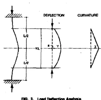
exposure to fire, the strength of the column decreases with the duration of exposure. 'lbe strength of the colnmn can be calculatl!d by a method based on a load.-deftc:ction or stabilit}' analysis (ADen and Lie 1974 ). In this method, the colum11s are idealized as pin...,nded cohiRUis of ef-fective length XL (Fig. l). The load on the colum11 is intended. to be ron· cenhic. Due to imperfections of !be oolumns and tbe loading device, some ea:eotricity exists. The loading system and the test columns were made witlthf8h precision, however. Therefore, in the calculations, a very small
arbi-trary load oo:entricity of 0.2 mm, refleetillg a nearly concentric load, has
been selected for the initial eecentricity. ·
The a:rrvature of the colwnn is assumed to vat}' from pin ends ro midheigbl aroordiog to a straight-line relation, as illustrated in Fig. 3. For such a relatioo, the deRection at mldheight Y, in terms of the cu>Varure セッヲ@ the oolnmn at 'Ibis beigbt, can be given by:
y _X (KL)-'
12 (17)
For any given cutvature, and thus for any given deflection at midbeight,
DEfl.ECTION CURVIITUAE
'
U2 IKMMセl@
--+Y-, I 1.12 'FIG. 3. u.d DIIIHtlaol ... ....,. ..
the axial strain is varied until 1M internalmnment at the midsection is in eqmlibrlum with the applied moment. i.e.
}: f,._.Am"Xm., = セ@ fm_.Am"(Y
+
e) (18) In !his way, a load-deflection curve can be calculated for any specifil: time dnring the exposure to fire. From these curves, tbe strength of the column, i.e., the maximum load that the columo can carry, can be determined for ・セセZ「@ time. In the calculation or rolumn stteagth, the following assumptions were made:l. The propenies of the steel and concnote are tho.., deocribed in Ap-pendix I.
2. Concrete has oc tensile strength. 3. Plane
tectioos
remain plane.4. There
isno
slip betweensteel
androncrete.
5. There is no composite anion between the steel and concrete. 6. 'The rcduellon In ccluom length before exposure to fire (oonsistiog of free shrinkage of tlte ronaete, creep. and llhorteoing of the colamn due to load) is neglisJble. This reduction can be eliminated by selecting the length of tbe shorteaed column as initial length from which tbe changes during exposure ro rne are determined.
Based on these assumptio11s, tbe column strength during expooure to fue was calculated. In tbe calculations, the-
network
of annual elements shown uo Fig. 2 was used. Because ャィセ@ strains lllld stres•es of tbe elements are nut symmetrical wilh respect to lite y-axls, lite calculations were pedonned for both the net\ll'ork sh.own and an i<kntical network to !he left of tbe )'-axis. Tbe load lltat the oolumn can carry and tbe ュ\セュ・ョエウ@ in tbe section were obtained by adding the loads carried by each element and rbe momentscontn'buted
by them.F.q10aliom for Conerete
The strain in エ「セ@ cmu:rete for the
elements
to the right of the y-IIXis セョ@be given by:
(8,)ft
= -(•,),
+
e
+
セ@
p and for the elemeniS to tbe left of the ケMエセクゥャゥ@ by:
(•Jt
セ@
·-(t,h+ • - ;
(19)
(20) where {t,}r = tbamal expansion of concrete, in millimeters -•; •
=
axial strain of tbe rolumn, in millimeters-•; "'' = horirontal distance from the tenter of the clement to a vertical plane tluouglly-axis of tbe ooiUIII.D section, in meters;and
p = radius of curvature, in meters.ne stre .. cs in lbe dements are calculated using tbe stress-strain relations Cor c:arbonate-aggrep.te concrete given in Appendix I (Uc 1992}.
EquatloasrorSWel
The strain in an dement of tbe steel can be given liS the sum of the
lhennal
expansion of the sreel (o,)T, tbe axial strain oftbe column •· and lbe strain due to bendinf of the column x,lp, where x, is the horizontal distsnce of the steel element to lbe venial I plalle through tbe y-axis ofthe rolumn section andpis
tbe radiuo of cuf\'ature. For the steel to the rigbt of they-axis (Fig. 2), the ウエイ。ゥョHセLILN@ is given by:(e,)R = - (•,}r
+ •
+
セ@
(2l)p
For tb.e steel elements to the left of they-axis. the Mrain (o,)L is !liven by:
(22) The stresses in the steel are calculated using the steel-strain relatiom for steel given io Appendix I (Ue 1992).
El(ullliuml f<J< Sleet Relnfon:emenl
The strlli11 in tbe steel reinforcing baJs """ be given as tbe sum of the thermal expansion of the steel HセNINMN@ the axial strain of the column x8/p
where
x
8 is the horizontal distance of tbe center of the section of steel bar ·to the verlkal plane through the y-axis of the column sedion, and p is tbe radius of Wf\'llture. For the steel ban at the right of the y-axis, tbe straln (a•)• is ァゥカ・セエ@ by:
(23) For tbe steel ba:n to the left of they-axis, the strain (•,.)L is given by:
( Xs
(E,.)L = - £a)T
+
£ - - ; (24)The stresses in the
steel
are calculated using thestress-straiu
relations for oteel given in Appendix I (Lie 1992).セャoイ@ CakuJollnn of C -Streqth
With tl1e old of (19) -(24) and equatitins in Appendix I, the stresses at midsection in the otcel and concrete elementB can be calculated for any value of the axial strain • and curvature l/p. From these stresoes, tbe load that eadl element carries and its contribution to the iotemal mOillent at mid· Jectiou can be deri..,d.
By
adding the loads and moments, the load that the column curies and tl!<o total internal moment at midsectiou can be calcu· lated.The fire resmance of tbe colum11 is derived by calculatill,g the str.,ngth of tbe column as a function of time of fire exposure. Thi• strength reduces
セwゥャャケ@ with time. At a certain point, the otrength becomes so low that
11 io no longer sufficient to support the toad. At this point, tl!<o column beoomes unstable and i• ... umed to have failed. The time to reaeb this fllilure poillt is the fire reoistance of the column.
TEST 8PECIMEN8
Two specimens, ・ッセウエゥッァ@ of boUow steel columns tilled with reinfurood aubonate-aggregate concrete, were tested and used to verifY. the model giveR in this paper. The test spccimcons are described in detail by Chabot 1111d Lie (1992} and are illustrated in Fig. 4.
The columns were 3,810 mm long from end plate to end plate. The outside diameter wat 1:73 mm IUid the steel wall thickoess was 6.3S mm.
The steel columRS were fabricated by cutting the steel to セイゥ。エ・@
lengtbll. Steel end plates were then welded to the column extr.,md.i..,.. Cen-tering and perpendicularity of tbe end plates were given speciAl attention to ensure a high degree of tweuracy. Before welding the end plates, a hole, . with a diam .. rer 26 mm smailer than the inner diameter of the hollow steel section. was cut in each plate. Be<:ause of the smaller diameter of the holes in the end plates, a lip of l3 mm to transfer tbe load from tbe steel plate
10 tbe concrete fillinll was crcJtted after weldiug, as shown in
Fis.
S. Four small boles were also drilled In tbe steel wall to provide vent boles for water vapour produced durins tbe experiment. Two holes were located opposite one another at 1 ,448 mm above midheigbt of the rolwnn: the other u.v weteloeated opposite one another at 1,448 mm below midheight of tbeeolumn.
The stee! of the columns had a specified yield strength of 3SO MPa. Deformed bms,
with
a minimam yield stlenglb of 400 MPa, were used for the maio reinforcing and tie bars. The diameter of reinforcing bars was 19.5 mm and tbat of the tics was 6.4 mm,The mam reillforciJ!s ban were tied together to oomplete the steel cage and were cut 10 mm shoner than the column length (Figs. 4 and 5). The steel ca$C was エィセョ@ placed into the column with special care
to
ei1Silre appropnate centering.The concrete wa• poured in tlte column through the top opening. Its composition, per cnbic meter of coru:rete mix, was as follows:
• Cement, 439 kg
o Water, 161 kg
• Fine aggregate, 621 kg
o Co:me aggregate, 1,128 kg
E E
..
セ@
r-I ...e.4
mm tiesV
-og
"2115 mmfャセ@ 4. Elevallan ond C... &ecllon ol Columna
Tile 28-day cylilldet strength was approximately 42 MPa. The average cyl-inder strength at the time of testing was approllimately 47 MPa.
Cluomel-alunocl thermocouples with a thickne.., of0.91 mm were installed at the midheight of the rolumn for measuring tbe temperatures of the steel reinforcement and concrete at different locations in the"'"""" <ection. The loeadoos of !he thel'IJ!<)C()uples are described in detail in • report by Chabot and Lie (1992).
lEST APPARArus
The tests were doJJe by exposing the columns to heat in a col11mn test fumare. The test furnace was designed to produce the conditions to whi<:h a member might be subjected during a fire. It consists of a steel fmmework wpported by fuur steel columns, with the fnrn.at"' chamber inside the frome-IIIOrk- The ·characteristics and instrumenmtion of the fumace. whiclt has a loading capacity of 1.(]00 t. are de<scribed in detail in Lie (1980).
lEST COIIIDITIOHS AND PROCEDURES
The tests were done with both ends of the columns fiXed. i.e., re•trained against rotation and horizontal translation.
l>,f>
<1.
End plate wllh opening
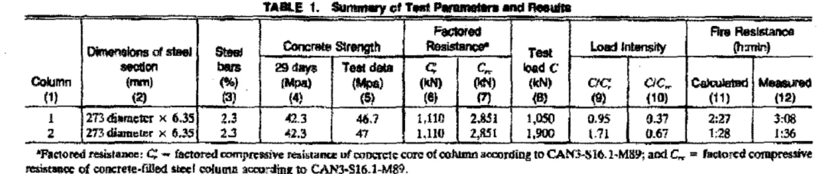
The oolumns were tested under a oonrentric load. The applied loads ...,re 37% and 67% of the factored compressive resistance of the oolumns ( cセス@ · or 95% and 171% uf the tilctored oompressi'lle resistance cf the concrete core (C:}, determined acoordillg to the Canadian Standard• Association standard CSNCAN.S16. l-M89 ("Unlit Stateo" 1989). The factored com-pressive resistances of each oolumn, as well as the applied luads, are given in Table I. The e£1l:cti¥C length factor K used in tbe calculation of the facton:d compressive イ・ウゥFセウ@ was that recommended in CSNCAN-SI6.1-M89 for the given end ooodition, i.e., 0.6S. The effective leqth of the
columns,
KL,was
thus assumed to be 2.48 m.During the test, the column was exposed to beating controUed in sucll a
way
that the average temperature in the furnace followed, as closely "" possible, the ASTM Ell'l-88 or CAN/ULC-8101 standard temperature-time curve.RESULTS AND COMIIEIII'$
Using the mathematical model described in this paper, the temperatures, axial deformations, and strengths of the rolumns wen: calculared. In the calculations, the thermal and mechonirAI properties nf tbe
corbonate-llg-gregateron<:rete
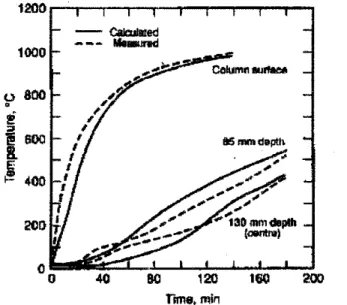
aod steel, given in Lie (1992), were used. These properties and the specifics of the キャセセセセエュ@ and tbc funuwe are given in Appendix II. In Fogs. 6 and 7, the calculated temperatures ar" compared with tbe temperatures meuured at lbe external surfaee of the steel •oction and at ¥arious depths in the concrete. With the exception llf the temperatures measured at an early stage, tbete is good agreement between calculated1500
g
TABlE 1. Su...,oiT.-I...,._and,__
- -··---·-·· MMMセM
Faclored
FinoResl-DinlenGlons
of-
Steel c。ョ」ョッセエセ@ Slrength Reoislanee' Test Load lnlansily {h:mlnJ-011
bars 29days Teal datac;
」セ@ loadCColumn (mm) (%) . fMpa) (Mpa) (leN) (14N) (kN)
ac;
CIC. セ@M...,
(1) (2) (3) (4) (5) (8) (7) (8) (9) (10) (11) (12)
-I 273 di•m.c1U X (>.35 2.3 42.3 46.7 1,110 2.851 l,!lSO 0.95 0.37 2:27
I
3o08 2 273 diamcler X 6.35 2.:! セRNS@ 47 1.110 2,851 1,900 l.71 0.67 1;28 I :.36-'Fie:tored r:e&Uitanoe:
c; -
factored compre:Mive rea.is1ana: ut ooocre1e- CO!'C! of coJumn accon:lin,g to CANl-Sl6.l ... MS9; acd C.... = faolor«< cO!llpreSSi'Ve....,.,.,... of eonc:rete·f!lle<l-1 oolumn •-rding 11> CAN3·SI6.1-M89.
1000
0 800
•
rcma.min
FlO. 8. Tem...,... at V1rtoua Dopllle of Column 1 n Fllnelkln of iJipclaul8 Time 1100 1000 900 800 0 700
•
e
セ@J
500 セPP@ 300 200 100 0 ·100 0 40 60 80 100 Time. TrinFIG. 7. T_...,. Ill -.alloptha of Column a • fii...Uan of Expoaure Time
and measured tolumn tempemtuces. The
temperatum
ュ・イオセオイ・、@ deeper insidl! the column sbow initially a relatively rapid rise up to tempemlures of 11pproximalely lOO"C, followedby
aporiod
of relatively olow rate of temperatwe rise. TI1is temperature behavior may be tbe result of thermally iDducecf migration of the moisture toward tbe e<>nter of tbe column where.20 - Calculaled
ID
-- • Measuredセ@
I --0...
_____
{
Mセ@ セセ@ セL@..
'
I
-10' '
'
\...
'
lt..
-20
\ \ <( \ \ -3D \ I I I I セP@ -40 BO 120160
200
'Tima, mloFlO. I. セMM・キ・」ゥaクャ・ャMャッョ。ッャ@ Cal..-t MFuncllonol
セtゥュ・@ 10 -Ca!QII-5
---
M-0
セL@セ@
--
--
Mセ@f
J.i...
...
...
·10....
i
·15' '
'
'
J
\ \·20
\ \ \ ·2S -·3D 0 20 40eo
eo
100nm ...
minf'IJ. 9. C..IIIU.--
---Axial
-Jan•
ol COlumnIf••
Fum:llan ol ... 111Mas shown in previous tests (Cbabot and Ue 1992),
theinfluence
ofmigration
is
most pronoo:mced. Altbo!tgb tbe model takes into au:ouot evaporarion of moisture, it does oot take buo aooount tbc mignltion of tbe moisture tQ\Yard tbe wnter. That migradon appears 10 acronor foe tbc deviation between calculated and measured temperature• at tbe earlier stases of fire exposure.4000 :!500 セ@ 3000
"'
12fi00
"' 2000 1500 1000 500 0o ao
40eo
110 100 1m 140 1so 110 200 220 T1me.minFIG. 10. セ」ッMョNNNNLNNN@
•
Func:tion Clfnme
。ョ、セ@ •nd-Fint--
AI the later stages, however, which are important from the point of vi"wof predicting !be fire rcsisiMce of the oolumns, !OOre is a good agreement between calculated
and
measuredtemperatures.
ln Figs. 8 and 9, the calculated and measured axial deformati<ms of the oolumns duritlg eJtposure to fire are shown. There is reuonably good agree- · men! in the trend of deforma!ioos between calculated and measured results. There are
some
differences, however, between tbe actual valuell of tbe ealeodared and measur·ed defonnatio11s.It must be noted that tbe rolumn deforms axially as a n:sult of several liu:tors-namely, lood, thermal expansio11, bending, and ereep-that can·
1101. be rompletely taken into account in tbe calculations. Since tbe aKial deformations, wbich are in the order of 20 mm, are for rolumos with a leagth of about 3,!l00 mm, small inaccuracies in thoae factors may callSe noticeable diffenlnces between calculated and rnell$nred rudal deformations. A difforenre of 10% betwem tbe theoretical and actual coelftcients of thermal eKpansion of steel, for example, will cause a 、ゥャヲ・イ・エセ」・@ of approx-imately 5 mm in tbe axial deformations.
· The effect of creep, wbich is more pronounced at the later stages of fire expoiiUre, may be even greater. The model define• 100 failure point as the point at which the o:olumn CM no kmger support tbe applied load and assumes tbat failure 91 this point is instantaneous. Duriqtbe tests, failure was not instantaneous bnt tbe 」ッャャddョセ@ contracted ronilderably, apparently as a result of oontinucd Joss of strength and creep, before thcr were crushed.
In
Fig. 10, the calculated column strengths, as a functoo11 of tbe fire-ClJIOSllfe time, are shown エッァ・エ「セイ@ witb tbe calculated and measured lire resistallCCS for the teat loads given in Table 1. The strength decreases with time until it beoomes so low !bat the columll cau no longersuppon tbeload. The time to ""'ch this point is tbe lire. resistance·oi
tbe column. The results show that tbe calculated fire resistance of column 1 is about20% lower andf',
i
I
!'
that of tolumn 2 about 10% lower than tbe measured foe resistances. The differences are probably caused mainly by the ronsiderel>le contraction of the columns, which the model can ooly partly take into lKCDUnt. For practical
セN@ lx•we•·er, the calcuJated fife resistances, which lie on the safe side, are reaoonab!y BeCurate.
CONCLUSIONS
Based on the fC$lllts of tltis study, the foUowing oonclusio!IS can be drawn: The mathematical model employed in this study is capable of predlding the fire resistance of circular columns, made of hollow sttuctural steel filled with bar-reinforced concrete, with an accuracy that is adequate for prac1icol pucposes. The results indicate tltat the model is ronservative in it• predic-tions.
The model will enable lbe expansion of data on the fire resistance of cirrular concrete-filled steel columns, which at present predominantly con-sists of data for culumns
filled
with plain ooocrele, with tbat for columns fiUed with bar-reinforced roncrete.Using the model, the fire resi.o;tance of circular COll<:rere-fiUed steel ool· umm can be evaluated for any value of the si.gnificant puameters-such as load. rolumn-oectioo dimen•inns, oolumn length, and percentage of rein-fon:ing steel-·-without the necaaity of tc•tins.
1'11!>
model can abo 「セ@ used for the calculation of tbe lire resistance of «>>unms made with concretes otltcr than those investigated in this study-for t:llample, lightweight or siliceou• 8Sf!tegate coJ!Creles that were not tes«ed-if the relevant material properties are known_ACKNOWLEDGMENTS
This work was carried out at the National Fire Laboratory of tbe ln.•tltute for Research in CWlSiruction. National Research Council of Canada, with the support of tbe Canadian Steel Construction Council and the American Iron and Steel Institute. The writer would like to thank Martin Chabot for his oontribotion in procasing tbe theoretical and experimental results, aDd John Mllel.aurin and John Latour for their usistance witb tbe exporimenl:!l. APPENDIX I. MA TEIIIAL PRDPERIIES AND SPECIFIC8 01"
COLU.S AND FURNACE CIIIKIH I'Nperdes
Swss-Strain Relations
For 1,:s
エセ@For
Ec>
£111111 where 1506 (ZS) (26)• - • 0.0025 + (6.0T
+
0.047"') x IO-• {27} and {; セ@ [:., for<rc;_
<
T<
451FC (28)/.
セ@イセ@
[
2.011 - 2.353」セZI}@
for 4SO"C "" T s 874"C (29)f:
=
0 for T>
874"C {30) Thermal Capacity p,.c, - 2.5'66 x 10' J/(m'"C) for 0 :s 1'::s
400"C (31) p,.c,=
HoNjWVNセtM 68.034) x 10'1/(m'"C) for400< Ts4tO'C (32) p,.c, セ@ (-0.05043T- 25.00671) X 10' Jf(m"'C} for410< To>445"C (33) p.,c,=
2.5'66 x 10' Jf(m'"C) for 44S<
T:S SOO"C (34) p.,c,=
(0.01603T -- 5.44881) x 10' Jf(m'"C) for 500<
Ts63S"C (35) p.c,=
(0.16635T- 100.90225>:
IIJ' J/(m'"C) for 635<
Ts 715"C {36) p.,c, = ( -0.22103T+
176.07343) x IIJ' J/(m''C} for 715<
Ts 785"C (37) p.,c, .. 2.566 x 10" Jl{m''C) for T> 785'C (311) TMrmol Conductivityk,
= 1.355 W/(m"C) for 0,;;T
:s 293"C (311) k, = -0.0012411'+
1.7162 Wl(m•q for T>293'C (40)COI!{ficiell! of Thermal E:qJanswn
«, セ@ {O.OOST
+
6) xto-•
mf(m'C) (4!) Sfr<•s-Strain R•lfllions fッイエNセ@ s: f.i,.. wbere and , _ f(T, 0.001} '·· - 0.001 e, (42) '• = 4 X 10-"f"' (43) f(T, 001) = (50 - 0.1141) X (I - exp(( -30+
0.031)'ViJ.OOi)] X 6.9 (44)For 1!1, > ep
/y
=OHセNセセAI@
•,.+
f(T, (t, - •,セ@
0.001)) -· f(T, 0.001) (45) where f(T, (•, - •• + 0.001)) = (50 - 0.041) X [1 - exp({- 30+
0.031)1/(£, - Bp+
0.001)}! X 6.9 (46)n. •
.,u/ Capacityp,.c, = (0.004T +3.3) x1Q6 J/(m3"C) for O'C s Ts 6SO'C (47)
p,.:,
= (0.068T+
38.3) X 10' J/(m''C) for 6SO"C<
T "'m•c
(48)p.c,
= ( -O.otlliT+
7:'1.3S) x UJ6 Jl(m"'C) for 725"C<
T ,; 800"C(49) p,.c, セ@
4.SS x
10" Jl(m''C) forT >
800"C (50}11otrmal Conduciivity
k, = - 0.022T
+
48 Wl(m'C) for O''C s T s 900'C (51)k, = 28.2 W/(m'C) for T
>
900'C (52)Coq{lt*nt of Thermal Expanslo11
a, = (O.OOIT
+
12) x 10 6 ml(m"C) forT< l,OOO'Ca,
=
16 xto-•
ml(m"C) Waitt Properties 111trmul (.llpacity forT?:
t,OOIJ"C p.c. = 4.2 x 10⁶ Jl(m"'C') Hmr of Vtqrorization Aw = 2.3 X 10' JlkgAPP!NDIX I. SPECI'ICS OF COlUMNS AND FURNACE
(53) (54)
HセUI@
(56)
n.c
ウー・」ゥヲセ。@ of columns and furnaces are: e, = emissivity of columnfurnace fire, 0.75; •· = emissivity of steel, 0.8; KL = etlecti.., length of mlumns, 2.0 m for fire·resislllnce calculations; I = length of colliiDn that contribu!es to aKial defmmatioo, 3.5 m; and
4>
= wnrentration ol moisture in concrete by volume, 0.10.APPENDIX IU. REFERt':NCES •
Allen, D. E., ar:td Lie, T. T. (191'4) ... funhcc studies. of tbe fue rcs.ista.RCC -Qt'
re.in-rorc;ed oom:rete oo!nmns." NRCC l41Hl. Nat. Reo. cッセゥャ@ of canada, Div. of
llldg. R<;s., Ottawa, Ontari<>.
OJabm, M • and Lie, T. T. (1992). "Experimental stu<lies on the
fire""'"''""""
of 1ti07hottow steel columns fiJI(d ;,..ith bar-reinforced cuncrete." IRC lnteriUII Rtport No.
1128, Nat. R ... Council of Olnada, last fe>r Rc1. in cッイオセエイNL@ Ottawa, Ontario. dオセョ|^ュ・L@ G. M. (1%1). HeJlt tran.rfrr mku/4Jirms by
finw
diffmnM.lnterna-li<mal Textbook C.. .. Scran!On, l'a.
Ue, T. 1'. (l!n7). "T•mperature dislributiom in fire-.. posed building oolumns." J. H<11t1hw{er, 9!1(1), 113-119.
l..ie, T. T. {1980). "New facility 1<1 detennine the lite m;istlnce of oolvmns.''
c.tn.
J. Civ. E>rgr1., 7(3 •• 551-SSB.
l..ie, T. T., ed. (199<!). "Struclllfal fire protection." Almlwlb onJ Reports"" E'lgi·
ntering pLNLNZセ。@ No. 78. ASCE, New Yorl, N.Y.
li<, T. T., lln, T. D., Allen, D. E., l!lld Abralll!, M.S. (1984). "Dre r<.<i•tance ol
roinl'orad ronr.rete ooiUIIIDs." DBR P•!H• No. 116'!, .VRCC 21065, Nat. Res. Olun<il ofC..aada, Div. of Bldg. R.,.., Ouawa, Ontario.
"Limit states desi&n of ll<d SUuctute!.." (191!9). CANICSA·SI6.l-M89, CBQ. Stan-dards-Assoc., Toroato, Ontario.
"Standard methods of lire endllrancc tc•ls of building conlltrue1:ioo and marerials." (1!189). CAN/ULC-SIOI, Underwriters' Lob. of Canada, S..'8tb<>rougb, Onwi<>. "Standard methods of fin:: ''"15 of boJ1ding oonsln><tion and materials." {!990).
ASTM E/19-811, Arn. Soc. for Teslillg and Mater., PhiWielphia, Po.
APPEHDIX r'l, NOTATIOH
The following symbols we
usedin
thitpaper:
A. セ@ area of element (nr);
C = load intensity;
c;
セ@ factored oompres•ive resistance of concrete core;C,.,
•o
factored compre•sive resistance of イッョ」イ・エセNMヲゥu」、@ oteel col· umns.;c
= specific beat Jll(kg"C)J;e
セ@ eccentricity (m);f
= stress (MPa);f
セ@ cylinder strength of concrete at temperature T (MPa);f'.-. = cylinder strength of concrete at room tempuature {MPa);
セM セ@ stren8th of steel at temperature T (MPa);
It = ooeflicient of beat ttansfer allitc-cxpooed surface [Wt(m"C)J;
i
= セN@ i, 2 .... ;K = effecti•e length factor:
k = thermal oondm:tivity (W/(m"C));
L " unsupported length of oolwnn (m);
I
=
Jtnsrh of column that contribute• to axial. deformation {m); M1=
nnmber of points Pin steel section in radial direction;M, = total ntunl:oer of points P in column oection in radial
direc-tion; ·
N, number of dements in tangential direction;
P = point;
R. = rndius
<>I
conctetc core (m);R, セ@ t"4WUS
<>I
steel wlwnn (m);T = temperature ("C);
V セ@ volume
<>I
moisture in an element (m');x
= coordinate (m);.Y = lateral deflection of columo at midheigbt (m);
y
セ@ coordinate (m);cr. = cooffi<.icnt of エAエ・イュ。ャNMセーbdウゥッョ@
(II"C);
1508
A i.m.n:ment or difterenoe;
Tセ@ m mesh width
in
radial direction (m);• =
emissivity, strain (rhlm); I. セ@heal
of vaporization (Jikg); p = deBSlty (kg/m3);u
セ@ Stdan-Boltzmmo constant [W/(m2K4}J;
T
=
time (b);4> "'
concentration of moi•ture; and)( --- cut\lllture
or
column .at midbeigltt {lim). S..bol:rlpiB8
=
stul reinfOrcement;c::
=
concrete;f
=
fiR;
L
=
left of )'-WS;m,
M1, M2 セ@ polo!$m,
M, and M, in radial diteetion;n,
N,=
pointsn,
and N1 in tanptial dlremon; o '="' room temperature;p = propo11lonal strea...ruain relation;
R