Flow Properties of Tailored Net-Shape Thermoplastic
Composite Preforms
S. T. Jespersen&F. Baudry&M. D. Wakeman&
V. Michaud&P. Blanchard&R. Norris&J-A. E. Månson
Received: 10 March 2009 / Accepted: 6 July 2009 / Published online: 16 September 2009
# Springer Science + Business Media B.V. 2009
Abstract A novel thermoplastic programmable preforming process, TP-P4, has been used to manufacture preforms for non-isothermal compression molding. Commingled glass and polypropylene yarns are deposited by robot onto a vacuum screen, followed by a heat-setting operation to stabilize the as-placed yarns for subsequent handling. After an optional additional preconsolidation stage, the preforms are molded by preheating and subsequent press forming in a shear edge tool. The in- and out-of-plane flow capabilities of the material were investigated, and compared to those of 40wt% Glass Mat Thermoplastics (GMTs). Although the TP-P4 material has a fiber fraction of 60wt%, the material could be processed to fill 77 mm deep ribs with a thickness of 3 mm, indicative of complex part production. The pressure requirements for out-of-plane flow were shown to depend on the fiber length and fiber alignment. Segregation phenomena were found to be less severe with TP-P4 than with GMT material.
Keywords Preforming . Consolidation . Thermoplastic . Composites . Commingled yarns
S. T. Jespersen
:
F. Baudry:
M. D. Wakeman:
V. Michaud:
J.-A. E. Månson (*)Ecole Polytechnique Fédérale de Lausanne (EPFL), Laboratoire de Technologie des Composites et Polymères (LTC), Station 12, CH-1015 Lausanne, Switzerland
e-mail: [email protected] P. Blanchard
Ford Motor Company, Ford Research and Innovation Center, 2101 Village Road, Dearborn, MI 48124-2053, USA
R. Norris
US Department of Energy, Oak Ridge National Laboratory, P.O. Box 2008, Oak Ridge, TN 37831, USA Present Address:
F. Baudry
Rieter Automotive Heatshields AG, Sevelen, Switzerland Present Address:
M. D. Wakeman
1 Introduction
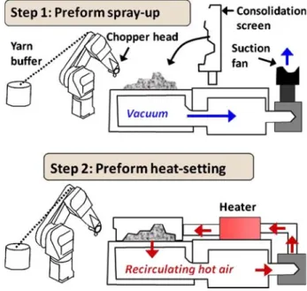
The TP-P4 technology is a net-shape preforming technique using commingled yarns of glass and Polypropylene (PP) fibers as the feedstock, as presented previously [1,2]. A chopper head mounted on a robot deposits the material onto a vacuum screen, as shown in Fig. 1. A porous screen then compresses the fibers while hot air is forced through the preform, melting the PP fibers. This creates a semi rigid preform which can be used for compression flow molding in a similar fashion to blanks of glass mat thermoplastic (GMT). This process is based on the original P4 process, which consisted of a net-shape preforming technique where glass fiber yarn was chopped and deposited with a powder binder (typically 5wt%) onto a vacuum screen. After a subsequent heat set cycle of the powder binder, the semi-rigid preforms were then injected in RTM and SRIM cycles using a variety of thermoset resin systems [3,4]. The process targeted waste issues associated with non crimp fabric (NCF) or textile materials. In previous work [1,2], it was shown that this process adapted to thermoplastic commingled yarns is suitable for making high volume fraction glass-PP preforms.
The applicability was demonstrated for compression molded plates and a double dome generic shape. The objective of the present work is to investigate the suitability of TP-P4 preforms as a bulk flow molding material, to be used in ribbed parts. However, since the glass fiber mass fraction of 60% is higher than that of traditional GMT flow molding materials (upper commercial limit of 40%) [5–8], flow behavior could be impaired and it is necessary to determine processing limits, and also consider potential segregation issues.
This article thus investigates the influence of preheating and transfer times on the out-of-plane flow of TP-P4 to determine initial conditions for subsequent detailed studies of TP-P4 flow behavior. Here a design of experiments approach was used to investigate the in-plane and out-of-plane flow as a function of material and process parameters, with particular
Fig. 1 Schematic of the preforming system with heat-set air blower system. a Deposition of fibers. b Heat-setting of the preforms
emphasis on potential segregation effects. Comparison with a commercially available GMT was also performed. Finally co-compression of these preforms with GMT was investigated.
2 Materials and Methods
2.1 Materials
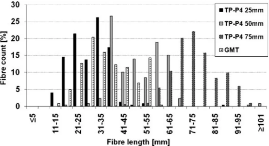
The material was 1870tex 60wt% glass/PP commingled yarn, known commercially as Twintex and produced by OCV reinforcements. The fiber length set-points chosen were 25, 50 or 75 mm. As benchmark material, the widely used 40wt% D110F40 GMT was chosen, supplied by Quadrant AG, with a measured average fiber length of 35 mm. The initial fiber length distributions will affect flow behavior, hence Fig. 2 shows the measured fiber length distribution, determined by more than 200 caliper measurements, for TP-P4 materials and GMT. The results indicate similar narrow length distributions enabling subsequent investigations to focus on the mean fiber length, which was 25 mm,50 mm and 75 mm for the TP-P4 material and 35 mm for the GMT, all with a standard deviation of ~10 mm [1].
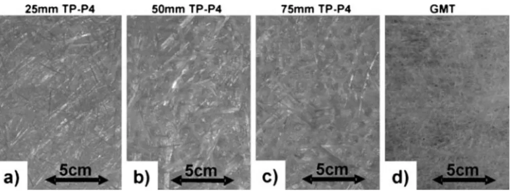
A photo of the surface of TP-P4 blanks and a GMT needled fiber mat is shown in Fig.3, where a globally similar 2D planar random structure is observed for the TP-P4 samples and a 3D structure in the needled GMT mat.
2.2 Hydraulic Press System and Tooling
Compression molding trials were performed using a fast acting Svoboda hydraulic press as shown in Fig. 4a. Combination of a 30 kW pump and two 50 L, 315 bar hydraulic accumulators enabled 800 mm/s daylight closure and 150 mm/s compression speeds over 75 mm to be achieved. Automated programmable closing and light curtains were used to eliminate closing delays. Stroke precision was 0.01 mm, with a highly rigid upper platen, although no closed loop parallelism control was used. A closing rate and compression speed of 800 mm/s and 70 mm/s were used unless otherwise stated.
The oven used was a 2 m3Ernst Reinhardt GmbH forced hot air convection oven (80 to 450°C) with oscillating tray. An air flow rate of 15 m/s measured at the tray was used for all trials unless otherwise stated.
A shear edge tool was used to keep pressure constant during cool-down. Exchangeable tool inserts enabled molding of either flat plates or plates with 77 mm deep ribs, as seen in Fig.4band (c). A tool temperature of 60°C was used unless otherwise stated.
3 In-Plane Flow
During the compression molding of thermoplastic composites, it is important that the matrix is sufficiently above melt temperature when pressure is applied both to fill the mould and reduce void contents. This is due to the non-linear drop in polypropylene viscosity with temperature, which defines flow behavior of the bulk concentrated suspension [6]. With the oven and press system used it was possible to obtain short transfer (~3 s) and fast closing and pressure build-up times (~2 s), reducing cooling of the preheated TP-P4 material and hence maintaining reduced polypropylene viscosities. The objectives were thus to investigate the bounds of the process to determine suitability of industrial press molding facilities and to generate process windows for the molding process.
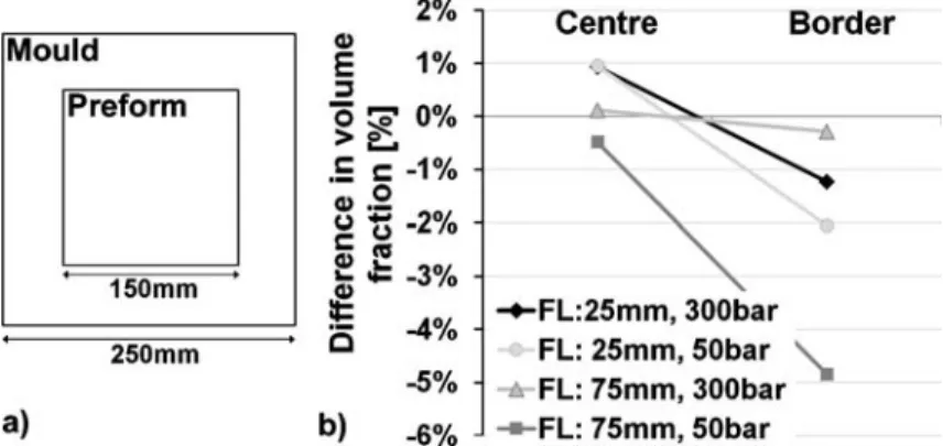
Taking the simplest case of in-plane material flow [9,10], the TP-P4 material behavior was examined. Six preforms were stacked giving a final part thickness of 4.7 mm and a mass of 428 g, Fig.5a. The two fiber lengths of 25 mm and 75 mm were used. The molding pressure was varied from 50 bar to 300 bar and the thickness was measured across the final part. For a mean plate thickness of 4.7 mm, no significant variation in thickness occurred for the different fiber lengths and molding pressures, with a standard deviation of 0.12 mm from 6 tests. Using burn-off tests of samples taken at the sample centre and border, Fig.5b, it is seen that a slight difference in fibre volume fraction occurs at the border, but in all
Fig. 4 a The press system. b The shear edge tool with removable inserts for flat plate or deep ribs and c the molded part dimensions; here with ribs
Fig. 3 Photos showing the surface fiber architecture; a,b,c TP-P4 preform before molding, d GMT glass mat before PP impregnation
cases it is less than 5% for the press forces and speed used here. The tendency for in-plane segregation is from Fig. 5 observed increasingly with lower pressures, as expected from earlier segregation studies of needled concentrated suspensions [11]. For non-needled preforms this behavior has been found to be less pronounced [12].
4 Out-of-Plane Flow
The out-of-plane flow limitations as function of processing parameters for the TP-P4 material was examined to guide potential use of this material in complex components where ribbing is often used.
4.1 Optimised Rib Fill
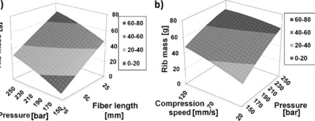
A design of experiments approach was taken, using a 3 factor 3 level array, Table 1, to determine the necessary press requirements to fill the rib-tool. The low, medium and high settings were based on extensive trial runs so that the lowest setting would approach fill of the tool and the highest setting would fill the ribs in a repeatable manner, in particular for the 25 mm fiber length. Three 2 mm thick (as pressed thickness) 216·216 mm2panels (Covering the rib-areas, but small enough to ensure easy placement in the mould) were heated to 220°C in a forced hot air oven and pressed to give a target molded part thickness of 3 mm, for a full mould. A time at pressure of 30 s was used, with a tool temperature of 60°C.
Complete filling of the mould was achieved at 250 bar with 25 and 50 mm panels. The 75 mm fiber length required an increase to 300 bar — a little outside the DOE bounds. Negligible warpage was observed with the naked eye (ribs almost parallel) and the base plate was visibly smooth and flat.
The average mass of the two ribs was used as a measure for the rib filling efficiency, Fig. 6. A t-test showed that the pressure and fiber length were the only significant parameters with 35% and 38% contributions respectively, at 95% confidence. Statistically significant interactions between parameters were not observed. Optimized conditions were: a pressure of 250 bar, 25 mm fiber lengths, and a compression velocity of 100 mm/s. The compression velocity dependence was seen to be small at high pressures, confirming that the velocity range chosen in the present work is above the restricting limit [11–14].
Fig. 5 a Blank placement. b In-plane flow using 6 blanks: effect of fiber length (25 mm and 75 mm) and pressure (50 to 300 bar) difference in fiber volume fraction compared with base material at 35vol%
With rapid transfer times and fast daylight closure, the tests have shown that the effect of a large compression velocity was lower than that of pressure and it is rather the press force that drives the material flow. Provided that sufficient pressure is used and the pressure build-up time is short (together with rapid transfer into the press from the preheat oven), it was considered that a press with 60 to 70 mm/s compression speed would suffice, as is used commercially today.
4.1.1 Rib filling
The rib filling results were analyzed after burn-off tests. Figure7presents photographs of ribs cut from three samples with different fiber lengths, all pressed at 300 bar and 70 mm/s compression velocity. These compression parameters were chosen based on the optimum parameters used in section 4.1., but with a slightly higher pressure to ensure complete mould fill with the 75 mm fibers, and with 70 mm/s to stress the mould less than what was experienced with 100 mm/s. The 25 mm fiber rib exhibits a more homogeneous structure with little apparent fiber alignment and fewer and small knots. At a 50 mm fiber length, knots were more apparent and the tip of the rib was seen to be almost transparent with a low fiber content. The 75 mm fiber length rib did not fill the mould completely in this case. There was a clear tendency of knot formation, especially in the areas where the rib did not fill, which is expected to limit the flow considerably. Additionally, flow induced fiber alignment could be observed in the rib flow direction.
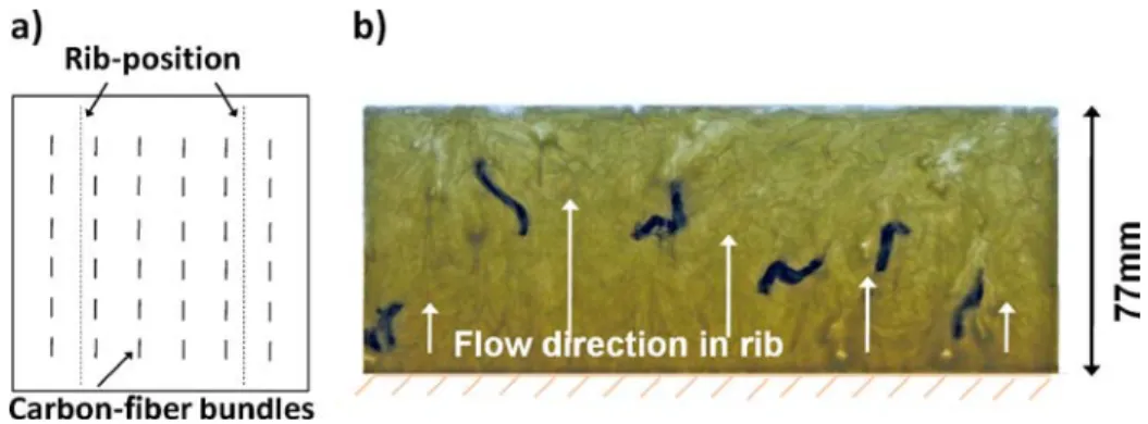
To further examine the flow characteristics, carbon fiber bundles were positioned in between two TP-P4 layers prior to compression molding, Fig.8ato act as a tracer for the TP-P4 material flow. From the resulting rib, Fig. 8b, the carbon fibers moved during fountain flow into the rib, decreasingly so towards the rib edges. This phenomenon was
Fig. 6 The average rib fill mass as function of a fiber length and pressure and b compression speed and pressure
Table 1 DOE parameters, no repeats used, but two ribs per stamping
Parameter Low Medium High
Fiber length [mm] 25 50 75
Pressure [bar] 150 200 250
repeatable since four ribs qualitatively showed the same pattern. When placing the carbon fibers at the preform surface no flow of the tracers was observed. For improved flow-pattern resolution ultra small metal wires could be used as tracers, which don’t influence the flow. However, the carbon fiber bundles clearly show the expected flow pattern and how it is important to retain heat in the preform centre to achieve deep rib design features.
4.2 Optimisation of Rest Time and Temperature
Following the optimization of pressure, compression velocity, and fiber length, the optimized parameters were used to study the effect and interactions between preheat temperature, transfer time, and fiber length.
4.2.1 Mould Rest Time and Fiber Length
During the compression molding operation, the hot TP-P4 preform is transferred from the oven onto the waiting steel tool. The press then closes and compresses the preform, but a short delay occurs, which is here denoted‘mould rest time’, while the press safety system operates, the hydraulics close the daylight gap and pressure is built up.
The effect of mould rest time and TP-P4 fiber length on the degree of rib fill was examined using the ribbed tool. In all cases the 2 mm (as pressed thickness) materials were pre-heated in a forced hot air oven to 220°C core temperature (340 s), and the press closed with an average of 300 bar on the material surface (assuming a full tool), with the molding
Fig. 8 Flow test done with a. carbon bundles laminated between two 25 mm fiber length TP-P4 layers. The resulting rib b processed at 300 bar and 70 mm/s compression velocity
Fig. 7 Backlit photographs of TP-P4 ribs at 300 bar and 70 mm/s compression velocity. The base of the rib is down. Letters were used to identify samples
tool maintained at 60°C. A compression speed of 70 mm/s was used, which was maintained for 30 s before the press was opened and the molded part removed. These compression parameters were chosen based on the parameters used in section4.1.1in order to be sure to fill the mould when using the fastest transfer time. It took approximately 3 s to transfer the samples by hand from the open oven to the press. Once in contact with the lower molding tool the operator moved to safety behind the light guards and pressure was applied, a further ~2 s were needed for this. The average weight of the two ribs was used as measure for the filling quality. Based upon instrumented trials, it was found that rest time in air during transfer was insignificant compared with the mould rest time, due to the faster heat transfer between metal and preform.
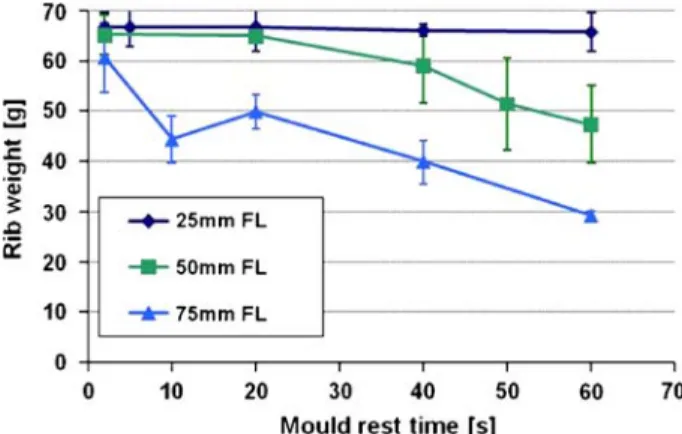
The mould rest time was varied between 2 s and 60 s to determine the effect on rib fill, for fiber lengths of 25, 50, and 75 mm. The two molded ribs were cut from the base plate after molding, and the average weight was used as a measure of degree of tool fill. Figure9 shows that mould rest times of 2–20 s had only a small effect for 25 and 50 mm fiber lengths, with fill dropping off for longer times. At 75 mm fiber length, any additional delay had a strong effect on degree of fill, due to the higher bulk suspension viscosity arising from stronger fiber entanglements. For the 25 mm samples the effect was small, but the part surface roughness increased with mould rest time for all samples.
As has been observed previously for GMTs [15], the lofted structure held the core of the TP-P4 preform away from the steel tool surface and insulated the core region from the surface such that the core region remained above the melt temperature and molding was still possible. The surface, however, cooled in contact with the tool and this local area froze, as also seen for GMTs. Outside of the original blank area the ribbed plate is filled by fountain flow [6] of the core region material. Increased mould rest times will result in the material available (i.e. sufficiently above Tm) for fountain flow to be reduced, and for increased energy to be required to force the now higher viscosity concentrated suspension through the mould cavity and into the ribs.
4.2.2 Temperature and Fiber Length
The effect of preform preheating temperature (150–220°C in preform centre) using the forced hot air oven at 220°C on the degree of rib fill was then analyzed. In all cases, the
Fig. 9 Sensitivity of rib average rib weight (two ribs) to the mould rest time versus TP-P4 fiber length. The upper and lower values from the two measurements are marked with error bars
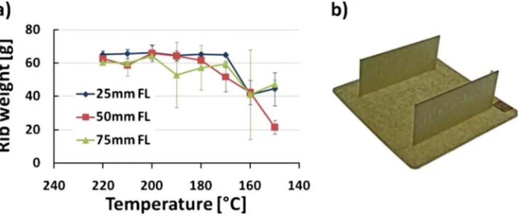
materials were transferred from the oven within 3 s, with subsequent press molding at 300 bar (assuming a full molding tool) with a tool temperature of 60°C, 2 s mould rest time, a compression speed of 70 mm/s, and hold time of 30 s. The average weight of the ribs was used as measure of flow. Figure10shows a limited effect of centre-temperature on the rib weight until a strong reduction appears below 180°C. Increased fiber lengths showed a marginal increase in the drop-off temperature. This was considered to be due to continued movement of hot intermediate layers in the bulky blank stack. The upper preheat temperature of 220°C was used in the other studies as this improved surface quality and gave the maximum degree of fill for all fiber lengths.
4.3 Comparison with GMT
In order to compare the flow behavior of P4 with a benchmark material, GMT and TP-P4 ribbed samples were molded at a 70 mm/s compression velocity, 30 s hold time at pressure and preheating to a centre temperature of 220°C. For the GMT material a pressure of 100 bar was used although the lowest pressure to fill the tool with GMT was ~80 bar, higher pressures were unnecessary to fill the mould. The TP-P4 was processed using 300 bar which just filled the mould for the 75 mm fiber length. We did not have 60wt% fiber fraction GMT available for the tests, nor did it exist commercially at the time of writing. By using different pressures, with which to just fill the mould, we used the conditions that would likely be used in industry where excess pressure would mean additional cost. The fiber content in the molded ribs was quantified by burning off the matrix of selected samples (vertical & horizontal) at 600°C for 60 min, and measuring the resulting fiber weight fraction.
4.3.1 GMT Burn Off
The measured GMT fiber fraction in the burnt off ribs was 36wt% vs. 40wt% in the initial material. The small difference shows that the fiber flow into the ribs is impeded, but not significantly, [16]. Figure 11shows micrographs of the vertically cut samples, indicating preferred fiber orientations and knots of fibers. There was no difference in fiber weight fraction for the most central sample compared with the outer samples. The fiber samples
Fig. 10 a Rib fill dependence of temperature and fiber length; Error bars show the standard deviation b Completely filled sample made with 25 mm long fibers
had a‘woolly’ feeling 3D-fiber structure compared with a more flat 2D structure in the TP-P4 samples.
On the horizontally cut sample specimens shown in Fig. 12, the change in fiber alignment from inner towards outer samples is pronounced. The fiber weight fraction for the most inner sample was 45.6wt% compared with the mid and outer samples having 38.5wt% and 21wt% respectively. The knots and general wall friction hence hold back the fibers in the 3 mm thick ribs.
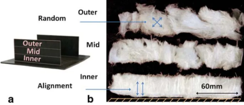
4.3.2 TP-P4 Burn Off
Following the same method as for GMT, TP-P4 was examined using burn off test samples in the vertical direction for three different fiber lengths, Fig. 13. For TP-P4, the average measured fiber content in the rib was 60wt%, the same as in the initial material, indicating even more consistent fiber movement than for GMT. Some segregation was observed towards the tip of the ribs. Some orientation was also observed in the flow direction especially for the middle sample towards the base. When comparing the flow pattern of GMT with TP-P4, the 40wt% GMT had a longer flow distance in-plane and out-of-plane at lower processing settings than the 60wt% TP-P4. This is to be expected because the volume fraction is much lower, inducing less fiber-fiber contact points which dominate the resistance to flow [11–14].
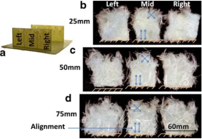
The horizontally cut samples are presented in Fig. 14, which showed increased fiber alignment towards the base. This alignment could be expected to influence the mechanical properties. For the medium 50 mm fiber length, the fiber fraction changed from 63.4wt%
Fig. 11 a Sample positions and b resulting fiber samples after burn-off
(inner) to 61.8wt% (mid) and 55.4wt% (outer). This segregation increased with fiber length, hence, the longer fibers are held back more than the shorter ones, albeit not substantially.
The fiber fraction results for the horizontally-cut samples are presented in Fig.15. This shows that in all cases the innermost sample has a higher fiber fraction than the base material, indicating that fibers are held back, and that this effect is increasing with fiber length for the TP-P4 material.
In comparison with the GMT material, the TP-P4 retained the fibers better in the outer part of the ribs with only a 7.6% decrease from base material to the outer sample compared with a 47.5% decrease for GMT which can make a large difference when the ribs are highly loaded, Fig.16.
These results indicate that, although the press requirements are clearly increased for the 60wt% TP-P4 materials, the segregation effects are much less marked than for the 40wt% GMT material, in particular for out of plane flow into ribs. A potential explanation is that GMT materials tend to segregate more easily, mostly because the needled fibers exert more resistance to break-up of the structure under flow, as reported in [12]. SMC materials, on the other hand, have a planar random, non-needled fiber structure, closer to that of TP-P4 materials, with glass fiber bundles cut and randomly deposited onto a layer of paste. These are much less prone to segregation [11]. Flow models based on flow of concentrated suspensions, as proposed in [17,18] could thus be applied to model TP-P4 flow in the future.
Fig. 13 a Sample positions and b c d resulting fiber samples after burn-off for 25 mm, 50 mm and 75 mm original fiber length respectively
Fig. 14 a Sample positions and b c d resulting fiber samples after burn-off for 25 mm, 50 mm and 75 mm original fiber length respectively
5 Co-Compression Flow Moulding
Since each material has specific mechanical properties and flow characteristics, they could be used together to take the best advantage of their respective properties. In order to evaluate the combination of TP-P4 with GMT, co-compression molding trials were carried out. The TP-P4 and GMT has a tensile modulus / ultimate strength of ~10 GPa/165 MPa and ~5 GPa/65 MPa respectively at 20°C [1]. TP-P4 material is structurally superior to standard GMT for two main reasons: it has a higher fiber fraction of 60wt% than 40wt% GMT and with TP-P4 the fiber length can be increased versus GMT. On the other hand, the lower fiber content and the special needling of GMT make the material flow to fill the rib-tool at ~80 bar versus 300 bar required for TP-P4, reducing investment in press costs.
Hence co-compression of both materials could be of interest to use TP-P4 as a structural inserts where the geometry is relatively simple and the loads are high, and GMT in more complex areas where a longer flow length is required, for instance to create thin stiffening ribs and reduce press tonnage requirements. To illustrate the possibilities offered by the co-compression of TP-P4 and GMT, several variants were produced, all TP-P4 with 25 mm fiber length; a few are presented here.
5.1 GMT Flow Through TP-P4
One test was carried out by placing a 145·145·5 mm GMT blank on top of two 217·217·2 mm TP-P4 blanks. These where preheated to 220°C and compression molded at
Fig. 15 Fiber fraction results for GMT and TP-P4 materials on a volume and b mass basis
Fig. 16 Results for GMT and TP-P4 materials showing the difference in fiber volume fraction from the base material
200 bar. The result in Fig.17ab show that GMT can flow through a TP-P4 preform and still fill deep ribs. A potential application would be to create stiffening ribs or other complex features on both sides of a TP-P4 insert, without the need to place GMT on both sides.
5.2 TP-P4 as Local Insert
Another experiment was carried out using TP-P4 as local insert together with GMT. One GMT blank of 221·221·5 mm was placed on top of two 150·150·2 mm TP-P4 preforms and then molded at 100 bar. The result, shown in Fig. 17c, illustrates the difference in flow properties. The TP-P4 material shows minimal displacement except for some outward flow where it is moved with the GMT. The GMT material on the other hand flow enough to fill the mould and the ribs, except in the TP-P4 insert zone. This trial shows that a TP-P4 insert can be positioned relatively precisely in a certain area of a part and keep the same position also after molding. Hence a part could be efficiently reinforced in critical areas by TP-P4 inserts.
6 Conclusions
Flow of TP-P4 materials was analyzed, and compared to that of GMT materials, for in-plane and out of in-plane flow. In-in-plane flow molding trials with TP-P4 material showed that a shear edge tool could be filled with a fountain flow mechanism similar to the benchmark GMT material. Press requirements to fill the mould with same dimension blanks were below 50 bar for both GMT and TP-P4.
Out-of-plane flow trials were performed to mould 77 mm deep ribs. This could be achieved with the TP-P4 material, even for 75 mm fiber length material. However, significantly increased pressures (300 versus ~80 bar) were needed compared with GMT to fill the mould cavity from the same dimension blanks. This is due to both the increased fiber length and mostly increased fiber volume fraction compared to GMT materials, which lead to an increase of the suspension overall viscosity, and of fiber-fiber contact points which dominate the pressure needed for flow. However, the segregation was much less important for the TP-P4 material than for GMT. GMT tend to segregate more easily because the glass preform is needled, creating additional entanglement and out-of plane fibers. From these results, it seems that TP-P4 with equivalent fiber volume fraction as GMT would show increased flowability, as is observed for SMC materials. It was however not possible to check this hypothesis, as glass-PP commingled yarns were not available for the trials with this low fiber fraction.
Fig. 17 Co-compression moldings showing a b GMT (black) flowing through the white TP-P4 material and c TP-P4 used as local insert
Finally, it is possible to combine both TP-P4 and GMT materials and co-mould them. This combination could allow the production of complex shapes with added reinforcement, while keeping the press requirements low.
Acknowledgements This work was supported by the EPFL and the Automotive Composites Consortium comprising Daimler Chrysler, Ford Motor Company, General Motors and the US department of energy and US Council for Automotive research (USCAR). The authors wish to thank J.Carron, D.May, D.Schmäh, L. Kämpfer and G.Pasche from the EPFL, J.Dahl, G.Smith, M.DeBolt, R.Cooper and D.Houston from Ford Motor Co., S.A.Iobst from GM and K.D.Yarborough and R.D.Lomax from Oak Ridge National labs as well as C.Ducret from Vetrotex. The authors would also like to acknowledge Quadrant for supplying GMT materials.
References
1. Jespersen, S.T. Baudry, F. Schmäh, D. Wakeman, M.D. Michaud, V. Blanchard, P. Norris, R. Månson, J.-A.E.: App. Compos. Mat 16(1), 55–71 (2009)
2. Jespersen, S.T., F. Baudry, M.D.Wakeman, V.Michaud, P.Blanchard, R.Norris and J-A.E. Månson Consolidation of net-shape random fiber thermoplastic composite preforms. Polymer Composites (2009). doi:10.1002/pc.20844
3. Corum, J.M. Battiste, R.L. Ruggles, M.B. Ren, W.: Compos. Sci. and Technol. 61(8), 1083–1095 (2001) 4. Chavka, N.G., J.S.Dahl. Proc. of SAMPE US symp. and exhib. Long Beach, USA. (1999).
5. Wakeman, M.D. Cain, T.A. Rudd, C.D. Brooks, R. Long, A.C.: Compos. Sci. and Technol. 58(12), 1879–1898 (1998)
6. Wakeman, M.D. Cain, T.A. Rudd, C.D. Brooks, R. Long, A.C.: Compos. Sci. and Tech 59(5), 709–726 (1999)
7. Wakeman, M.D. Cain, T.A. Rudd, C.D. Brooks, R. Long, A.C.: Compos. Sci. and Tech. 59(8), 1153– 1167 (1999)
8. Wakeman, M.D. Cain, T.A. Rudd, C.D. Brooks, R. Long, A.C.: Compos. Sci. and Tech. 60(10), 1901– 1918 (2000)
9. Tornqvist, R. Sunderland, P. Månson, J.A.E.: Compos. Part A 31, 917–927 (2000) 10. Tornqvist, R. Sunderland, P. Månson, J.A.E.: Polymer compos 21(5), 779–788 (2000) 11. Dumont, P. Orgeas, L. Favier, D. Pizette, P. Venet, C.: Compos.: Part A 38, 353–368 (2007)
12. P. Dumont, L. Orgéas, C. Servais, V. Michaud, D. Favier and J.-A. E. Månson, Proc. of ESAFORM 8, Cluj-Napoca, Romania, 2005
13. Servais, C. Luciani, A. Månson, J.-A.E.: J. Non-Newtonian Fluid Mech. 104, 165–184 (2002) 14. Servais, C. Michaud, V. Månson, J.-A.E.: Polymer Compos 22, 298–311 (2001)
15. Comprehensive composite materials, Pergamon Press, 2000
16. L. Orgéas, P.J.J. Dumont, V. Michaud and D. Favier, Int. J. of Mat. Forming, 2008. 17. Dumont, P. Orgeas, L. Le Corre, S. Favier, D.: Int. J. of Plasticity 19, 625–646 (2003)
18. Dumont, P. Le Corre, S. Orgéas, L. Favier, D. Gabori, C. Lory, P.: Eur. J. of Comp. Mech. 13, 883–900 (2005)