Publisher’s version / Version de l'éditeur:
Vous avez des questions? Nous pouvons vous aider. Pour communiquer directement avec un auteur, consultez la première page de la revue dans laquelle son article a été publié afin de trouver ses coordonnées. Si vous n’arrivez pas à les repérer, communiquez avec nous à [email protected].
Questions? Contact the NRC Publications Archive team at
[email protected]. If you wish to email the authors directly, please see the first page of the publication for their contact information.
https://publications-cnrc.canada.ca/fra/droits
L’accès à ce site Web et l’utilisation de son contenu sont assujettis aux conditions présentées dans le site LISEZ CES CONDITIONS ATTENTIVEMENT AVANT D’UTILISER CE SITE WEB.
Acoustics Week in Canada 2009, Annual Conference of the Canadian Acoustical
Association [Proceedings], p. 13, 2009-10-14
READ THESE TERMS AND CONDITIONS CAREFULLY BEFORE USING THIS WEBSITE. https://nrc-publications.canada.ca/eng/copyright
NRC Publications Archive Record / Notice des Archives des publications du CNRC :
https://nrc-publications.canada.ca/eng/view/object/?id=2874c716-49c0-43ce-a240-53e742995c8e https://publications-cnrc.canada.ca/fra/voir/objet/?id=2874c716-49c0-43ce-a240-53e742995c8e
NRC Publications Archive
Archives des publications du CNRC
This publication could be one of several versions: author’s original, accepted manuscript or the publisher’s version. / La version de cette publication peut être l’une des suivantes : la version prépublication de l’auteur, la version acceptée du manuscrit ou la version de l’éditeur.
Access and use of this website and the material on it are subject to the Terms and Conditions set forth at
Characterizing flanking transmission paths in the NRC-IRC flanking
facility
http://www.nrc-cnrc.gc.ca/irc
Cha ra c t e rizing fla nk ing t ra nsm ission pa t hs in t he N RC-I RC Fla nk ing
Fa c ilit y
N R C C - 5 1 3 8 9
K i n g , F . ; S c h o e n w a l d , S . ; S a b o u r i n , I
O c t o b e r 2 0 0 9
A version of this document is published in / Une version de ce document se trouve dans:
Acoustics Week in Canada 2009 (Annual Conference of the Canadian Acoustical
Association), Niagara-on-the-Lake, Ontario, Canada, October 14-16, 2009, pp. 2
The material in this document is covered by the provisions of the Copyright Act, by Canadian laws, policies, regulations and international agreements. Such provisions serve to identify the information source and, in specific instances, to prohibit reproduction of materials without written permission. For more information visit http://laws.justice.gc.ca/en/showtdm/cs/C-42
Les renseignements dans ce document sont protégés par la Loi sur le droit d'auteur, par les lois, les politiques et les règlements du Canada et des accords internationaux. Ces dispositions permettent d'identifier la source de l'information et, dans certains cas, d'interdire la copie de documents sans permission écrite. Pour obtenir de plus amples renseignements : http://lois.justice.gc.ca/fr/showtdm/cs/C-42
CHARACTERIZING
FLAN
PATHS
IN
THE
NRC-IRC
FLANKING FACILITY
Institute for Research in Construction, National Research Council, Ottawa, Ontario, Canada [email protected]
al flanking paths for the 6 junctions of the
ss (TL) of each flanking path for
e measurement results p
the commission
T : sion paths b two
izontal side-by-side rooms.
# gTransmission Paths
KING
TRANSMISSION
Frances King, Stefan Schoenwald, Ivan Sabourin
1. INTRODUCTION
This paper is the third of a series of papers that provide an overview of work conducted by NRC in the past years on flanking transmission. In the previous papers the measurement system and the new NRC-IRC Flanking Facility are described1,2. The ISO 10848 method for measuring flanking paths is time-consuming and not feasible for a facility of this complexity. This paper describes the methodology used in the Flanking Facility to systematically measure airborne sound transmission through the individu
specimen.
2. METHODOLOGY
Between two adjacent rooms there is 1 direct path through the partition and a total of 12 flanking sound transmission paths (3 for each of the 4 junctions, shown in Table 1 for the horizontal side-by-side case) and even diagonal room pairs that are connected by only one junction have four flanking paths. The room arrangement in the Flanking Facility allows evaluation of 8 horizontal, 4 vertical, 8 diagonal and 8 cross diagonal room pairs. The relative importance of these paths will depend on the properties of the floor, ceiling, party wall and side walls and of the junctions. Hence, extensive research studies are carried out in the Facility to characterize the sound transmission lo
different specimens3,4,5.
ISO 10848 suggests to measure all flanking paths one-by-one by shielding the surfaces of all other building elements that are not part of the considered path, but are either excited in the source room or radiate sound into the receive room. In the NRC-IRC flanking facility, 16 mm gypsum board on 90 mm glass wool is put in front of the building elements as shielding with no rigid connection to the test specimen. However, applying shielding to horizontal surfaces, the floor or ceiling, is not always feasible. In the NRC-IRC facility, some flanking paths are characterized with a slightly modified approach by extracting single path data from measurements with different shielding conditions. For example, the paths listed in Table 2 are measured between two lower horizontal rooms of the Flanking Facility using both the ISO standard and the modified
approaches as described below. Th
resented in Figure 1 are for the specimen that was used for ing of the Facility2.
able 1 Direct and flanking transmis etween hor
Path Direct and Flankin Airborne
#1 Party Wall–Party Wall Direct
#2 Floor–Floor Flanking
#3 Floor–Party Wall Flanking
#4 Party Wall–Floor Flanking
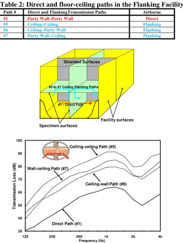
#5 Ceiling–Ceiling Flanking #6 Ceiling–Party Wall Flanking #7 Party Wall–Ceiling Flanking
#8 Side Wall–Side Wall (1) Flanking
#9 Side Wall–Party Wall (1) Flanking
#10 Party Wall–Side Wall (1) Flanking
#11 Side Wall–Side Wall (2) Flanking #12 Side Wall–Party Wall (2) Flanking #13 Party Wall–Side Wall (2) Flanking
#5 to #7 Ceiling Flanking Paths
#1 – Direct Path #8 to #10 #11 to #13
through the permanent
wall-#2 to #4 Floor Flanking Paths
The Flanking-TL of the ceiling-ceiling (#5) path in Figure 1 is measured according to ISO 10848. For the measurement, only the party wall and one pair of the side walls that belongs to the specimen have to be shielded in both rooms since measures have been taken to suppress sound transmission between the rooms
shell of the Facility1 which forms one pair of side walls and the floor of the considered rooms.
The remaining paths in Table 2 are obtained with the modified approach. The shielding is removed from the party wall in the receiving room and the TL due to the
ceiling-wall (#6) and the ceiling-ceiling (#5) path is measured. The
TL of the ceiling-wall (#6) path shown in Figure 1 is obtained by subtracting the TL of the ceiling-ceiling (#5) path from the measured data. Similarly, the TL due to the
wall-ceiling (#7) path and the ceiling-ceiling (#5) path is
obtained by moving the shielding from the party wall in the source room to the receiving room. The TL of the
ceiling (#7) (Figure 1) is obtained by subtracting the TL of
Finally, all shielding is removed from the party walls and the TL due to all four paths of Table 2 is measured. Since the TLs of three of the paths are known, the remaining direct path (#1) can be extracted.
For the side wall paths listed in Table 1 (#8 to #10 or #11 to
s emati r flanking paths (#3 t can be c acte upper rooms of the Facility. The fl king vertical and diagonal r irs can also be estimated following e same methodology.
Table 2: Di anking Facility.
Path # Di Airborne
#13), they can be characterized by shielding all the party walls and changing the shielding condition of the side wall
yst cally. The floo o #5) har rized in the
an paths of the oom pa th
rect and floor-ceiling paths in the Fl
rect and FlankingTransmission Paths
#1 Party Wall–Party Wall Direct #5 Ceiling–Ceiling Flanking #6 Ceiling–Party Wall Flanking #7 Party Wall–Ceiling Flanking
`
Facility surfaces Specimen surfaces
#5 to #7 Ceiling Flanking Paths
#1 – Direct Path Shielded Surfaces 30 125 250 500 1k 2k 4k Frequency (Hz) 40 50 T ra n s m is60 70 80 90 100 s ion Los s ( d B ) Ceiling-ceiling Path (#5) Ceiling-wall Path (#6) Direct Path (#1) Wall-ceiling Path (#7)
Figure 1: TL of ceiling-ceiling, wall-ceiling, ceiling-wall and direct path between two rooms separated by a party wall.
3. LIMITS OF MEASUREMENT METHOD
Although this paper shows that the applied method works fine, its limitations are discussed in this section. In Figure 2, the TL of the direct, the ceiling-wall and ceiling-ceiling path is presented for an extended frequency from 63 Hz to 4 kHz. Below 125 Hz, the TL of all three paths are very low and converge around the Apparent-TL. Hence, the applied shielding is not effective at low frequencies - most sound is transmitted directly through the shielded party wall – and the TL of all flanking paths is underestimated. Similar to the limitation of TL due to the mass-spring-mass resonance of double leaf walls (leaves are the masses and the spring is the air in the cavity), the TL of the shielded wall (now a system
with 4 masses coupled by 3 springs) is limite nances. The shielding could be improved by incr e mass of the applied gypsum board. which ge
kes the shielding method even more impractical vious study6 has shown that it is reasonable to h a 6 dB increase per octave band to the m
king TL below 315 Hz as shown in Figure 2.
d by
reso easing
th nerally
ma . Thus,
pre fit ‘tails’
wit easured flan 30 60 70 80 90 100 on Los s ( dB ) Ceiling-ceiling Path Ceiling-wall Path Fitted "Tails" (slope 6 dB/oct.) 10 20 63 125 250 500 1k 2k 4k Frequency (Hz) 40 50 T ra ns m is s i Horizontal Apparent Direct Path Estimate of Ceiling-wall Path from sum of direct and Ceiling-wall path
Figure 2: Shielding limits at low frequencies – flanking TL with fitted “tails”; Conservative estimate of Ceiling-wall path
due to small measured differences (grey)
Another limitation that affects the extraction of flanking paths is discussed in the following. In the example in Figure 1 an ideal case is presented with rather big differences in measured TL because the flanking path with the highest TL was measured separately. But in some cases the measured differences are small, and sometimes less than the repeatability uncertainty of measurements despite the high precision measurement system1. In such cases, only a conservative estimate can be defined as shown below. It is assumed that in this example the TL of the direct path with smallest TL is measured separately. The difference of this TL to the apparent TL due to transmission by the direct path and by any other ceiling paths that is measured next is small. If it is less than the measurement uncertainty of 1 dB then it could certainly not be related to a change of the
underestimates the flanking TL as e in Figure 2.
on
shielding condition. In the extraction of the path data, the difference must be assumed to be 1 dB. This gives a conservative estimate for TL of the second path that is only 7 dB greater than the TL of the direct path. In most cases this estimate grossly
shown by the grey lin
Like every measurement method, the one applied in the NRC-IRC Flanking Facility has its limitations. Hence, thorough planning of the tests and care in the data analysis is required.
REFERENCES
1
Estabrooks T., “NRC-IRC Computer Controlled Acoustic Measurement and Quality System”, Canadian Acoustics, V37, No3, 2009
2
Estabrooks T. et al., “NRC-IRC flanking sound transmissi facility”, Canadian Acoustics, V37, No3, 2009
3
King F., Sabourin I., “The effect of resilient channels on ceiling flanking transmission paths”, Canadian Acoustics, V37, No3, 2009
4
Sabourin I., et al.,, Effects of structural load and joist type on flanking sound transmission, Canadian Acoustics, V37, No3, 2009
5
Nightingale T.R.T. et al., “A hierarchy of flanking transmission paths in lightweight wood frame construction”, Internoise 2009
6
Nightingale, T.R.T. et al., “HFlanking Transmission in Multi-Family Dwellings: Phase IVH”, Research Report 218, NRC-IRC, 2006