Biotemplated Silica and Silicon Materials as
Building Blocks for Micro- to Nanostructures
The MIT Faculty has made this article openly available.
Please share
how this access benefits you. Your story matters.
Citation
Dorval Courchesne, Noémie-Manuelle et al. “Biotemplated
Silica and Silicon Materials as Building Blocks for Micro- to
Nanostructures.” Chemistry of Materials 27.15 (2015): 5361–5370.
As Published
http://dx.doi.org/10.1021/acs.chemmater.5b01844
Publisher
American Chemical Society (ACS)
Version
Author's final manuscript
Citable link
http://hdl.handle.net/1721.1/107467
Terms of Use
Article is made available in accordance with the publisher's
policy and may be subject to US copyright law. Please refer to the
publisher's site for terms of use.
Biotemplated Silica and Silicon Materials as Building Blocks for
Mi-cro- to Nanostructures
Noémie-Manuelle Dorval Courchesne,⊥§ Stephen A. Steiner III,‡§ Victor J. Cantú,‡§ Paula T. Hammond,*⊥§ Angela M. Belcher,*‡§ ⊥ Department of Chemical Engineering, Massachusetts Institute of Technology, 77 Massachusetts Avenue, Cambridge, MA,
02139, USA
‡ Department of Materials Science and Engineering and Department of Biological Engineering, Massachusetts Institute of
Technology, 77 Massachusetts Avenue, Cambridge, MA, 02139, USA
§ The David H. Koch Institute for Integrative Cancer Research, 500 Main Street, Cambridge, MA, 02139, USA
ABSTRACT: Silicon is essential in several energy-related devices, including solar cells, batteries and some electrochemical systems.
These devices often rely on micro- or nanostructures to function efficiently, and require patterning of metallic surfaces. Currently, constructing silicon features at the micro- and nanoscale requires top-down energy-intensive processes, such as e-beam lithography, chemical etching or anodization. While it is difficult to form silicon in aqueous solution, its oxide, silica, can easily be synthesized using sol-gel chemistry and nucleated onto templates with diverse shapes to create porous or continuous architectures. Here, we demonstrate that novel silica nanostructures can be synthesized via biomineralization, and that they can be reduced to silicon using magnesiothermal reduction. We selected three biotemplates to create silica structures with various aspect ratios and length scales. First, we use diatomaceous earth as a model silica material to optimize our process, and we also biomineralize silica onto two micro-organisms, the high aspect ratio M13 bacteriophage, and the helical Spirulina major algae. During our process, the shape of the materials is preserved, resulting in silicon nanowires, nano-porous networks, spirals and other micro- and nano-structures with high surface area. Our method provides an alternative for the creation of silicon nanostructures, using pre-formed silica synthesized in solution. The process could be extended to a broader range of microorganisms and metal oxides for the rational design of on-demand micro- and nanostructured metals. In addition, we show that the intrinsic composition of the biotemplates as well as their growth medium can introduce impurities that could potentially be used as dopants in the final silicon structures, and that could allow for tuning the composition of n-doped or p-doped biotemplated silicon for use as semiconducting building blocks.
INTRODUCTION
Metalloid silicon is of paramount importance for several indus-trial applications, including the fabrication of semiconductors, solar panels and high strength alloys. In addition to using bulk silicon, there has been a growing interest in creating micro- and nanostructured silicon materials for applications in hybrid sili-con-organic photovoltaics,1 lithium-ion batteries,2-3
micro-elec-tronics,4 and even sensing devices.5-6 Organizing silicon into
continuous structures can be used to improve charge transport, and creating high surface area networks could contribute to its reactivity and efficiency as an anode material. Silicon has the highest known theoretical charge capacity as an anodic material in lithium ion batteries,7-9 and therefore developing new
meth-ods for the synthesis of high surface area silicon materials with on-demand nanostructures is of great interest. In addition, sili-con is widely used for photovoltaic applications, and nanostruc-tured silicon thin films are currently being explored for use as antireflection coatings, and in hybrid silicon solar cells which are inexpensive, low-temperature alternatives to conventional silicon solar cells.1, 10
Currently, patterning silicon is often carried out via top-down approaches, which include lithography combined with harsh chemical etching techniques,11-14 electron-beam lithography, 15-17 or anodization18-19 of silicon wafers. While these methods
have been widely employed to create structures with simple ge-ometries like silicon posts, pillars or nanowires, complex shapes
cannot be achieved with these top-down approaches. A few novel silicon structures, including nanocrystals,2021 nanorods22
and nanowires,23 were also synthesized in high boiling point
or-ganic solvents and supercriticals fluids, but it remains challeng-ing to form silicon under ambient and mild conditions. The abil-ity to template metalloid silicon onto pre-assembled scaffolds with a desired shape would open up new possibilities for this material in the field of nanotechnology.
While silicon, due to its highly negative reduction potential, cannot be reduced from precursors in aqueous solution,24 silicon
dioxide or silica, is a material that can easily be synthesized via sol-gel reactions. Silica nanoparticle gels can be formed in so-lution, and subsequently nucleated onto scaffolds and templates that take on a variety of shapes. Now, with magnesiothermal reduction (MGTR), a process that has been recently developed to reduce metal oxides into their metal counterparts while pre-serving their shape, we can envision converting silica structures into metalloid silicon. MGTR was first investigated in the 1970’s and 80’s to prepare metals like boron25 and titanium.26-27
It was first applied to biologically-derived silica in 2007,28 and
since then, interest in creating various silicon nanostructures via MGTR has grown.
MGTR is the vaporization of magnesium at relatively low tem-perature (650 to 750 °C), and the reduction of a metal oxide,
such as silica, upon contact with its vapor. While silica is re-duced to silicon, the vaporized magnesium is oxidized to mag-nesium oxide. This process can be carried out at temperatures considerably lower than the melting point of silicon (1414 °C), which allow for preserving the shape of the silica structure that is being reduced, in contrast with carbothermal processes that require temperatures above 1700 °C and cannot be used to cre-ate nanostructures.29-30 It therefore allows for the formation of
a variety of silicon structures with a precise control over the po-rosity, three-dimensional structure and grain size by exploiting and controlling well-known silica chemistries. During the past decade, MGTR has been employed to produce nanoporous sili-con using diatoms31, mesoporous silica granules, 32, silica
parti-cles grown on inorganic templates,33 and rice husks34 as
precur-sors.
In order to produce a broader variety of silica shapes, with more complex or finer structures, we turned our attention to biologi-cal templates. Viruses, bacteria, algae and other microorgan-isms have a plethora of shapes that could be of interest for tech-nological applications. They often exhibit complex morpholo-gies containing turns, coils, angles, and pores, and their size var-ies from tens of microns for algae to nanometers for viruses. In addition, they can be organized into three-dimensional hierar-chical structures via bioconjugation techniques to create porous films or arrays.35-36 Proteins found in microorganisms like
dia-toms37 and sponges383940 can catalyze the formation of
biotem-plated silica. Silica can also be mineralized onto biotemplates with different shapes and length scales, and the silica structures can be reduced while preserving the shape of the template. Scheme 1 shows an overview of the biomineralization and mag-nesiothermal reduction process.
Scheme 1. Silica bio-mineralization and magnesiothermal
re-duction process. The process starts with a biotemplate onto which silica nanoparticles are nucleated. After annealing at high temperature to decompose the template and sinter the na-noparticles, the biotemplated silica is introduced into the mag-nesiothermal reactor along with Mg powder. The reactor is equipped with heating coils and insulation to reach the temper-ature required for magnesium vaporization and to maintain it. Argon is flowed in the reactor and any remaining magnesium vapors are collected in mineral oil at the outlet of the reactor. After the reaction, the silicon product is collected and impurities are removed with acid rinses.
The magnesiothermal reduction of silica proceeds as shown in Equation 1. Solid silicon powder is contacted with magnesium vapor, and is reduced to silicon.
SiO2(s) + 2 Mg(v) → Si(s) + 2MgO(s) (+ Mg2Si(s)) (1)
Magnesium oxide and magnesium silicide are formed as solid by-products, but can be easily rinsed off using an acid. For in-stance, with hydrochloric acid, magnesium oxide reacts to form magnesium chloride which is soluble in water (Equation 2), and magnesium silicide converts to micro-quantities of silane gas which bubbles out of solution (Equation 3). All purifications of the silicon products should be carried out in a fumehood to con-tain the toxic silane vapors and prevent exposure.
MgO(s) + 2 HCl(aq) → MgCl2(aq) + H2O (2)
Mg2Si(s) + 4HCl(aq) → SiH4(g) + 2 MgCl2(aq) (3)
After rinsing off the by-products, the product is a pure silicon structure with the same shape as the biotemplate. The silicon product can be porous or continuous depending on the shape of the template and the silica mineralization conditions.
Of particular interest for the formation of silicon is diatoma-ceous earth (DE), a natural and abundant source of silica formed by the skeletal remains of diatoms. We used these natural fos-silized silica structures as model low aspect ratio structures. In addition, many other microorganisms including viruses and al-gae can be used to nucleate silica nanoparticles. Here, the M13 bacteriophage, a filamentous bacteriophage, is used as a tem-plate to create silica nanowires. With its high aspect ratio – the phage has a length of 880 nm and diameter of 6.5 nm - the M13 bacteriophage is well known to generate fine nanowire-like structures upon biomineralization.4135 Spirulina major, a
coil-shaped blue-green algae also serves as a template for silicon mi-cro-coils. Spirulina major was recently used to mineralize tita-nia42 and copper4344 while preserving its spiral-like structure.
We are therefore interested in demonstrating the use of this complex shape for the formation of silicon.
In this work we demonstrate our ability to bio-mineralize silica using the M13 bacteriophage and Spirulina major as templates, and to magnesiothermally reduce the products to silicon to form high surface area materials with defined nanostructures. Alt-hough the magnesiothermal reduction of DE has been previ-ously demonstrated28 and applied to battery anodes45 and
pho-toelectrodes,46 we also use DE as a model organism to optimize
the magnesiothermal reduction process. We then apply the op-timal conditions to our biotemplated silica to produce novel sil-icon morphologies. We provide characterization of the mor-phology, elemental composition, and crystallinity of all biotem-plated silica and silicon samples, and show that upon reduction, the as-synthesized amorphous silica is converted to nanocrys-talline silicon and that the shape of the biotemplate is preserved throughout the process. In addition, we show that it is possible to first assemble the biotemplates into porous thin films, and then nucleate silica and reduce the thin films via magnesiother-mal reduction to create porous silicon films with nanowire-like features. Interestingly, our results indicate that the novel coil and nanowire-like silicon morphologies that we present here could also act as semiconductors. We show that microorgan-isms have the potential for serving both as templates and sources of dopants for the production of semiconducting sili-con. Our ability to produce high surface area and porous silicon materials could be extended to other metals and open up oppor-tunities for using these materials to create aerogels, light weight structures and other useful porous metallic structures.
EXPERIMENTAL SECTION
Materials. Tetramethylorthosilicate (98%) (TMOS), silicon
tetrachloride, ammonium hydroxide solution, dimethyl sulfox-ide (DMSO), and magnesium powder were purchased from Sigma (St-Louis, MO). 3-isocyanatopropyltrimethoxysilane was purchased from Gelest (Morrisville, PA). Diatomaceous earth powder was purchased from DiatomaceousEarth.com (Lewisville, ID).
The E3 M13 bacteriophage variant was amplified by infecting exponentially growing Escherichia coli bacteria, and was sepa-rated and purified via centrifugation. DNA sequencing con-firmed that the SFAAEEEDPAK peptide was displayed on each pVIII protein.
A starter culture of Spirulina major Alga-Gro® Seawater Me-dium were purchased from Carolina Biological Supply Com-pany (Burlington, NC). 8 mL of Spirulina culture was added to 200 mL of growth medium in a sterile flask, and grown for at least 10 days without agitation, alternating between 12 hours in light and 12 hours in the dark.
Bacteriophage-templated silica nanoporous network syn-thesis. 100 µL of NH4OH solution was added to 5.6 mL of
DMSO and thoroughly mixed. On ice, 8e14 pfu of
bacterio-phage dissolved in 1.5 mL of water was added to the mixture. Ice was used to cool down the heat of mixing that was produced. The DMSO/NH4OH/phage mixture was then added to 50 µL of
TMOS in a separate vial, which was left at room temperature for 3 hours. The resulting entangled silica nanowires were pre-cipitated by adding ethanol and toluene, and centrifuged down at 3000 rpm for 10 min. After further rinsing with ethanol, the silica nanowire pellet was dried in a vacuum oven at 80 °C over-night. To remove residual salts, the dried phage-templated sil-ica was rinsed with milli-Q water, collected by centrifugation and dried again, twice. The bacteriophages were burnt off and the silica annealed in a tube furnace in air at 500 °C for 12 hours. Two more rinses with water, centrifugation and drying steps were performed to clean the nanoporous silica.
Porous bacteriophage-based silica thin film synthesis.
Na-noporous bacteriophage thin films were assembled via covalent layer-by-layer, as described previously.35 The films were rinsed
with milli-Q water. A 0.2 M SiCl4 solution was prepared by
slowly pouring concentrated SiCl4 on iced water, with agitation
and allowing the ice to melt to form a solution. The bacterio-phage films were immersed in this solution and incubated for 1 h at 80 °C. The silica-coated bacteriophage films were then rinsed with milli-Q water, blow-dried with nitrogen and an-nealed in air at 500 °C for 12 hours.
Spirulina-templated micro-coil synthesis. A section of
Spir-ulina biofilm was taken directly from the growth flask and transferred into milli-Q water to rinse off minerals and salts. The rinsed film was deposited on a non-stick Teflon-lined sur-face and rinsed several times with acetonitrile. The film was then incubated on this surface for an hour in a 20 vol% 3-isocy-anatopropyltrimethoxysilane solution in acetonitrile, and then rinsed with acetonitrile. An overnight incubation in a solution containing TMOS and ammonium hydroxide (NH4OH) in
DMSO followed, and the silica-coated biofilm was finally rinsed several times with DMSO and dried via lyophilization. To remove carbon and burn off the biotemplate, the silica-coated Spirulina film was exposed to oxygen plasma for 1 hour, and annealed at 500 °C for 12 hours in air in a tube furnace.
Final rinses with milli-Q water and drying cycles were per-formed to clean the micro-coils.
Magnesiothermal reduction. A known mass of silica powder
was placed in a stainless steel boat, along with magnesium pow-der in an adjacent boat (in general 10 mg of silica and 10 mg of magnesium), and pushed to the middle of a (1 in in diameter by 10 in in length) tubular reactor. Alternatively, a ~ 1 cm2 thin
film of silicon was placed in the reactor along with 2 mg mag-nesium. Argon was flowed through the reactor at a rate of 100 sccm, and the temperature was elevated to at least 600°C for 3 hours. After cooling down, the silicon product was removed from the reactor and residual MgO and Mg2Si by-products were
dissolved by immersing the sample in 1 M hydrochloric acid for 12 hours. The purified silicon product was thoroughly rinsed in milli-Q water, and dried in air.
Nanomaterial characterization. The morphology of the
nano-materials before and after magnesiothermal reduction was char-acterized using transmission electron microscopy (TEM) with a JEOL 2010 FEG Analytical Electron Microscope and scanning electron microscopy (SEM) with a Helios Nanolab 600 Dual Beam Focused Ion Beam Milling System. Spirulina-based ma-terials were also observed by optical microscopy using a Leica LEITZ DMRX light microscope with a Nikon digital camera DXM1200F. The surface composition and chemistry of the samples was analyzed by X-ray photoelectron spectroscopy (XPS) with a PHI Versa-Probe II X-ray photoelectron spec-trometer with a scanning monochromated Al source (1,486.6 eV; 50 W; spot size, 200 μm). X-ray diffraction (XRD) was used to evaluate the crystallinity of the samples, using a PANa-lytical Multipurpose Diffractometer and zero background hold-ers. The surface area of the materials was measured by the Brunauer, Emmett and Teller (BET) technique, using an ASAP 2020 BET and monitoring nitrogen or krypton gas adsorption and desorption.
RESULTS AND DISCUSSION
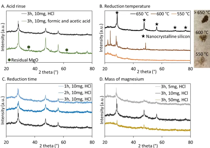
DE was used as a model microorganism to demonstrate and op-timize our magnesiothermal reduction process. The top panel of Figure 1 shows the morphology and color of DE before re-duction. Using this abundant source of biotemplated silica, the reduction time and temperature were varied, as well as the mass of magnesium and the nature of the acid used for the post-re-duction rinse (see Supporting Information, Figure S1, for XRD data). We established that the reduction must be carried out for 3 h in order to fully convert amorphous silica into crystalline silicon, and that the temperature should be kept at 650 °C or higher in order for the reaction to proceed. For a 10 mg silica sample, an equivalent mass of magnesium was found to be op-timal for the reduction, which corresponds to a 2.5:1 Mg:SiO2
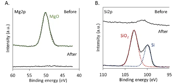
molar ratio. A slight excess of magnesium is therefore desirable for the reaction to proceed. The by-products were easily re-moved by a rinse with a strong acid like HCl, while traces of MgO could still be detected by XRD after rinsing with a com-bination of two weak acids, acetic acid and formic acid. XPS also showed a complete removal of MgO after acid rinse (see Figure S2).
Under optimized conditions, reduced DE exhibit the morphol-ogy shown in the bottom panel of Figure 1. Before and after MGTR, it consists of a mixture of diatom shapes that are con-sistent with previous reports of reduced DE.31 As indicated on
the images, the size of the DE features decreased by almost two times. The diameter of cylindrical diatomaceous earth changed
from 15.2 ± 2.2 μm to 8.4 ± 2.2 μm. In addition, a drastic change in color occurred and indicated the presence of nano-sized silicon after reduction.
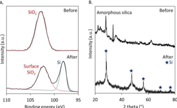
Figure 1. Upon magnesiothermal reduction, diatomaceous
earth features shrink, but their shape is preserved. SEM and optical images of DE before (top) and after (bottom) reduction. For a 3 h magnesiothermal reduction at 725 °C, the surface composition and crystallinity of DE were characterized, as shown in Figure 2. While only silica can be observed on the surface of the sample before reduction, silicon can be detected in the final product (XPS Si2p peak around 98.5 eV). Surface oxides are still present in the product due to normal oxidation of the surface during HCl rinse and under ambient atmosphere. If desired, these oxides could be removed via HF etching, but we did not perform this treatment in this work. XRD also indi-cates the presence of amorphous silica in DE before reduction, and shows peaks characteristic of nanocrystalline silicon after reduction. The additional peaks observed before reduction are attributed to salts and trace clay minerals that are also present in DE.47
Figure 2. Magnesiothermal reduction converts amorphous
di-atomaceous earth silica to nanocrystalline silicon. XPS spectra
showing the Si2p region (A) and XRD spectra (B) for DE be-fore and after a 3 h reduction.
The magnesiothermal reduction process was then applied to bi-omineralized silica using M13 bacteriophage as a template. Sil-ica nanoparticles were nucleated onto M13 bacteriophages in solution using TMOS as a precursor, and the reaction proceeded as shown in Equation 4. Dimethylsulfoxide (DMSO) was se-lected as a solvent in order to prevent denaturation of the bacte-riophage template.
Si(OCH3)4 + 2 H2O → SiO2 + 4 CH3OH (4)
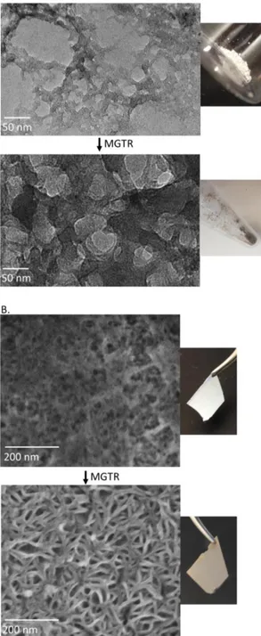
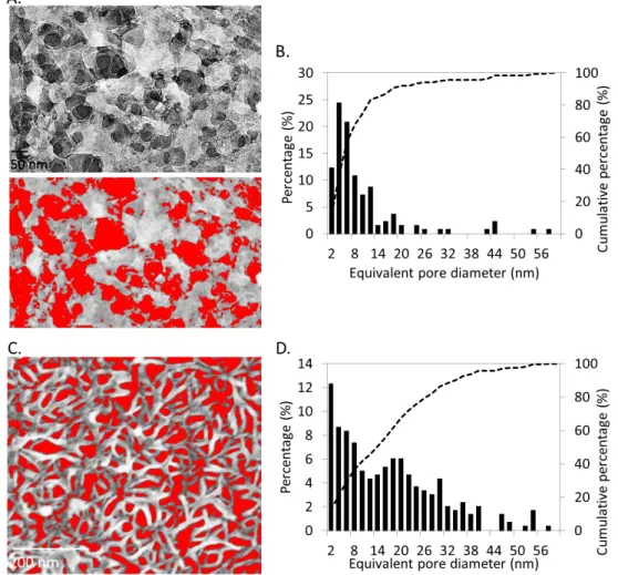
The reaction time was optimized (see Supporting Information, Figure S3), and after a 3 h reaction, bacteriophage-templated nanoporous silica with a structure shown in Figure 3A (top) was synthesized. High aspect ratio features resembling entangled flexible and curved nanowires can be observed, with a nanowire diameter in the order of 10 to 15 nm and an average of 11.2 ± 1.8 nm. These nanowires form a porous network of silica. After drying the product, annealing the structure and burning off the bacteriophage template at 500 °C in air, a white powder was obtained. The bottom panel of Figure 3A shows the product after magnesiothermal reduction and acid rinse. This product exhibits a high porosity (~ 40 %, with pores generally smaller than 25 nm in diameter, see Supporting Information, Figure S4 for details) derived from the silica nanowire network, but its macroscopic color changed from white to dark brown/black, in-dicative of the conversion of silica to silicon.
Silica nanoparticles can also be nucleated onto a pre-assembled biotemplated network. For instance, M13 bacteriophages as-sembled into a porous thin film using a covalent layer-by-layer assembly process35 can be fully infiltrated with silica
nanopar-ticles using silicon tetrachloride as a precursor. By immersing the bacteriophage thin film in an aqueous SiCl4 solution, the
precursor hydrolyzes and silica nucleates specifically onto the thin film (Equation 5).
SiCl4 + 2 H2O → SiO2 + 4 HCl (5)
Figure 3B (top) shows the structure of the resulting bacterio-phage-templated silica film after burning off the bacteriophage template. When the template is removed, the silica nanoparti-cles nucleated along the phage sinter together to form filled fine nanowires. Similarly, this thin film was magnesiothermally re-duced, and its final surface morphology is shown at the bottom of Figure 3B. A well-defined network of silicon nanowires is then created uniformly onto the substrate, which exhibits a dark color after reduction. The diameter of the nanowires is in aver-age 11.5 ± 1.2 nm. The porosity of the silicon thin film ap-proaches 30 %, and pores have diameters smaller than 40 nm with an average of 17 nm (see Supporting Information, Figure S4). This method provides a means to uniformly coat large sur-faces with porous silicon. It also allows for the formation of considerably finer silicon features compared wtih those previ-ously achieved to form mesoporous silicon via MGTR.4849
Figure 3. Silica and silicon interconnected nanoporous
net-works are produced with the M13 bacteriophage as a template. A. TEM and optical images of M13 bacteriophage-templated silica (top) and reduced silicon (bottom) nanowires synthesized in solution. B. SEM and optical images of silica (top) and re-duced silicon (bottom) nanoporous networks templated by an LbL-assembled M13 bacteriophage thin film.
Bacteriophage-templated silica and silicon powders were char-acterized via XPS and XRD (Figure 4). XPS shows that the surface content of silica decreases upon reduction and that re-duced species are also present (Si2p peak showing the presence of silicon and sub-oxides around 99.7 eV). From XRD meas-urements, it is determined that bacteriophage-templated silica was amorphous, and that it is converted to nanocrystalline sili-con after magnesiothermal reduction.
Figure 4. M13 bacteriophage-templated amorphous silica
nan-owires are converted to nanocrystalline porous networks of sil-icon. XPS spectra showing the Si2p region (A) and XRD spec-tra (B) for M13 bacteriophage-based silica and silicon nan-owires synthesized in solution before and after reduction.
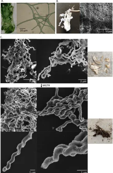
Spirulina major was used as a third biotemplate to produce
sil-ica and silicon structures. After at least 10 days of growth, the algae could be harvested as biofilms, and observed under opti-cal microscope to reveal loose coil structures (see Figure 5A). The diameter of the Spirulina coils ranges between 2.5 and 3 μm, and a turn spans ~ 4.5 μm. Conveniently, Spirulina bio-films exhibit a mechanical resistance that allows them to stay intact when removed from the growth medium, and to maintain their shape even after silica nucleation. To nucleate silica on
Spirulina biofilms, a silane with an isocyanate functional group
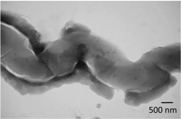
was used to first nucleate silane molecules onto the polysaccha-ride layer that is known to surround each Spirulina algae (see Supporting information, Figure S5, for a TEM image showing
Spirulina with its native polysaccharide layer). 50 This takes
place because the hydroxyl groups that are present on the sur-face of Spirulina can react with the isocyanate functionalized silane molecules. Then, TMOS was used to synthesize a thicker layer of silica along the algae. Figure 5B shows a Spirulina biofilm lyophilized after silica biomineralization. Spiral-like entangled structures can be observed by SEM.
To remove the Spirulina template, the silica-coated biofilm was oxygen plasma treated for 1 h, and then annealed in air at 500 °C for 12 h. Figure 5C shows that the micro-coil shapes are preserved after burning off the template, and that individual spi-ral structures can be observed. After magnesiothermal reduc-tion, similar silicon structures can be observed (see Figure 5D). Both for the Spirulina-templated silica and silicon, large entan-glements of micro-coils are found and result directly from the structure of the Spirulina biofilm. Individual coils correspond to free algae that were mineralized with silica, or algae at the edge of the biofilms. The size of these individual hollow silicon structures is constant, with a diameter of 0.7 ± 0.1 μm. SEM with elemental mapping confirmed the presence of silicon co-localizing with the coils observed (see Supporting Information, Figure S6).
In addition to the change in color of the Spirulina-templated biofilms observed before and after reduction (see Figure 5C and 5D), XPS confirmed the presence of additional silicon chemis-tries after reduction, including a peak corresponding to metal-loid silicon (around 99.5 eV). A single silica peak was meas-ured before reduction, while fitting indicates that silicon is pre-sent in addition to surface oxides and sub-oxides in the sample after reduction (Figure 6A). As shown in Figure 6B, XRD also
confirmed the transformation of amorphous silica into bulk nanocrystalline silicon after reduction.
Figure 5. Silica and silicon micro-coils are formed using Spir-ulina major as a template. A. SpirSpir-ulina major biofilm, as grown.
B. Lyophilized silica-coated Spirulina biofilm. Optical image (left) and SEM image (right). C. Magnesiothermal reduction of
Spirulina-templated silica. SEM and optical images of ulina-templated silica after annealing (top), and resulting Spir-ulina-templated silicon (bottom).
Figure 6. Spirulina-templated amorphous silica is converted to
nanocrystalline silicon upon magnesiothermal reduction. XPS spectra showing the Si2p region (A) and XRD spectra (B) for
Spirulina-templated silica and silicon micro-coils.
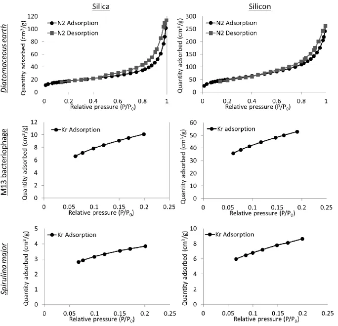
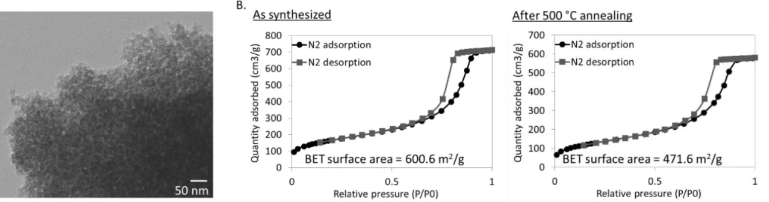
Quantifying the surface area of biotemplated silicon is of great importance for incorporating it in actual devices with specific design requirements and constraints. Large surface area mate-rials are often desired to create large contact areas between two materials that may lead to increased reaction rates, or more ef-ficient transport phenomena. On the other hand, a lower surface area might be desirable to reduce recombination rates in photo-active devices. We therefore assessed the surface area of our materials before and after magnesiothermal reduction. First, compared with a silicon nanoparticle control synthesized with-out biotemplate, the surface area of all biotemplated samples is lower (See Supporting Information, Figure S8). This difference results from the higher order organization of the nanoparticles along the biotemplates, to create high aspect ratio structures with reduced exposed surface area. Second, the data presented in Table 1 shows that, for all biotemplates, the surface area sig-nificantly increases upon reduction. This increase is due to the loss of oxygen atoms from the materials, as well as the change in crystallinity. M13 bacteriophage-templated nanoporous sili-con exhibits the largest surface area of approximately 271 m2/g.
Conversely, Spirulina-templated silica and silicon have a smaller surface area compared to their diatom or bacteriophage-templated counterparts, which is consistent with the larger length scales of the Spirulina templates.
Table 1. BET Surface Area (m2/g) of Biotemplated Materials
Increases when Silica is Reduced to Silicon. Isotherms can be found in Supporting Information (Figure S7).
Biotemplate Silica Silicon
Diatomaceous earth 64 188 M13 bacteriophage 51 271 Spirulina major 19 43
We also estimated the silicon crystallite size in our biotemplated samples. This parameter can be of importance in terms of con-centration of surface defects and interfaces within the material, and also for determining the properties of nanoscale silicon ma-terials. The particle size of silicon in each of the samples was therefore calculated from their XRD spectra, using the Scherrer equation. Overall, the particle size ranges between ~10 and 25 nm, as shown in Table 2. Silicon templated using DE and the M13 bacteriophage have similar crystallite size, while silicon templated with Spirulina major has significantly larger particle size. This can be explained by the longer silica nucleation per-formed on the Spirulina templates. Because the features of
Spirulina major are much larger than that of the M13
bacterio-phage, a longer TMOS hydrolysis and condensation is neces-sary to fully cover the surface of the algae. Consequently, the silica and silicon particle size also increases since the reaction proceeds for longer. These results are also consistent with the lower surface area of Spirulina-templated silicon. In addition, smaller silica particles were expected to be nucleated onto the surface of M13 bacteriophages compared to Spirulina major be-cause of the proximity of the nucleation sites on the coat pro-teins of the bacteriophages. Often, using M13 bacteriophages to nucleate materials tends to reduce the particle size.51
Table 2. The crystallite size for biotemplated silicon was
calcu-lated from XRD spectra using the Scherrer equation. Biotemplate Crystallite size (nm) Diatomaceous earth 11.9 ± 2.9
M13 bacteriophage 13.3 ± 1.3
Spirulina major 23.9 ± 2.9
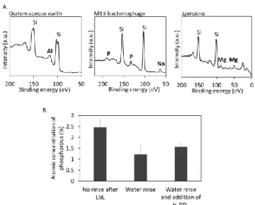
Although the conversion of silica to silicon is complete upon magnesiothermal reduction, other trace elements are found in the final biotemplated silicon materials, and their role needs to be understood in order to apply the materials to energy-relevant devices. In DE-based silicon, the main trace element found is aluminum, at an atomic concentration ranging between 0.2 and 1 % (Figure 7A left panel). The presence of Al is not surprising since DE is composed primarily of silica, but can also contain some clay minerals such as alumina. Upon magnesiothermal reduction, the alumina present in DE is reduced to Al, which could act as a p-type dopant in the final product. On the con-trary, phosphorous is present in the final bacteriophage-tem-plated nanoporous silicon, at an atomic concentration of 0.4 to 2 % (Figure 7A, middle panel). This P content likely originates from the DNA of the bacteriophage, and from the buffer solu-tion chosen to suspend the bacteriophages. Nonetheless, the presence of P in silicon nanowires is promising for applications as n-type semiconductors. In Spirulina-templated silicon, mag-nesium is observed at an atomic concentration of ~ 0.3 % (Fig-ure 7A, right panel). The presence of Mg is due to the chloro-phyll pigment found in this algae, which contains an Mg center. Even after acid rinsing the magnesiothermally reduced
Spir-ulina-templated silicon materials, Mg is still present, indicating
that it must be trapped within the silicon structure. Such Mg-doped silicon spirals could be used as n-type semiconductors.52
In addition to phosphorous, a high sodium content was initially found in the bacteriophage-based nanowires if no water rinse was performed after synthesis. Water rinses at various steps of the process are necessary for fully removing sodium ions (See Supporting Information, Figure S9). Rinsing silicon templated onto LbL-assembled bacteriophage films also allows for tuning the concentration of phosphorous in the nanoporous silicon thin films from approximately 1 to 2.5 %, as shown in Figure 7B. If the bacteriophage films are taken directly after LbL assembly, they can contain as much as ~ 3 % phosphorous, due to the phosphate buffer used during LbL assembly. However, when the films are thoroughly rinsed with water after assembly, the phosphorous content is decreased to ~ 1%. Adding dopants, such as phosphoric acid during the silica mineralization, also allows for modifying the phosphorous content in the final sili-con film.
The 1 % P content observed after rinsing the LbL films is con-sistent with the theoretical maximum amount of phosphorous that could dope silicon directly from the bacteriophage DNA. Considering the crystalline density of cubic crystals of silicon, one can determine that 8 Si atoms compose one unit cell, with a known cell volume of (0.543 nm)3.53 This corresponds to a
silicon atom density of 5e22 Si atoms/cm3. Then, the volume of
a bacteriophage-based silicon nanowire can be approximated as a cylinder of 880 nm in length, and the total number of silicon found in such a wire can be easily calculated. The phosphorous concentration deriving from the bacteriophage DNA is thus
simply the ratio of the 7222 P atoms found in the 7222 bases that constitutes the single-stranded DNA genome of a bacterio-phage,54-55 over the number of silicon atoms in a phage-based
silicon wire. Based on the geometry of the bacteriophage-based silicon nanowires, the phosphorous content due to DNA in a bacteriophage-templated silicon nanowire reaches 0.2 to 1 %. This percentage thus refers to the minimum phosphorous con-tent in bacteriophage-templated silicon, and is equivalent to a dopant concentration of 1e21to 5e21 P atoms/cm3, resulting in
heavily n-type doped materials.
Other trace elements could be introduced on-demand in the var-ious biotemplated silicon materials by changing the microor-ganism growth and purification conditions, and the buffer solu-tions used at different stages of the process. Further experi-ments could lead to the production of useful biotemplated sem-iconductors and the precise quantification and tuning of the re-sulting n-type or p-type carrier concentrations.
Figure 7. Intrinsic biotemplate composition and growth
me-dium or buffer components contribute to doping the final silicon products. A. Sections of XPS survey scans showing the impuri-ties in reduced biotemplated silicon. B. Phosphorous concen-tration in silicon templated onto LbL-assembled bacteriophage films, with or without rinses or phosphoric acid addition. The concentrations were averaged from at least three surface XPS measurements.
In addition to tuning the composition of the final biotemplated silicon products with impurities, the nature of the products can be modified by the process conditions. More specifically, car-bides and nitrides can be synthesized instead of metals if bio-templated oxides are magnesiothermally reduced without burn-ing off the organic template, or if the MGTR is carried out under a nitrogen environment, respectively. Scheme 2 summarizes the materials that can be synthesized by varying process condi-tions. For all the data presented in this work, the first process flow was followed; (1) the biotemplate was burnt off at high temperatures or using a combination of plasma treatment and high temperature annealing, (2) inert argon gas was flowed through the MGTR reactor, and (3) a metal or metalloid was obtained. If this process flow is modified by leaving the bio-template in, the large amount of carbon present during the MGTR will cause the appearance of carbides. In the case of silica, the expected product will be silicon carbide. Alterna-tively, if the biotemplate is burnt off, but nitrogen is flowed through the reactor instead of argon, then nitrides can be
formed. After reducing silica, silicon nitride is the expected product.
Scheme 2. Three different process routes lead to different
prod-ucts after magnesiothermal reduction: metals, carbides or ni-trides.
For a reaction carried out under nitrogen and with silica still containing the bacteriophage template, we have observed the formation of silicon nitride and silicon carbide (see Supporting Information, Figure S10, for details). Silicon carbide and sili-con nitride materials could also be applied to useful devices. For instance, porous silicon carbide could be of interest for the fabrication of temperature-resistant membranes due to the high thermal shock resistance of this material combined with its re-markable mechanical properties, or for use as a thermoelectric material due to its high thermal conductivity.56-57 Silicon nitride
also has attractive properties for a variety of applications. For example, it can act as an antireflective coating in photovoltaic devices,58 and has also been studied for incorporation in
wave-guides.59 Combining silicon nitride and silicon carbide
materi-als has materi-also attracted interest for taking advantage of the prop-erties of both materials and improving mechanical and dielec-tric properties of the product.60
CONCLUSIONS
In conclusion, we have demonstrated that combining a biotem-plated approach to nucleate silica nanoparticles along with mag-nesiothermal reduction represents a versatile process to create silicon nano- and microstructures. Complex shapes such as coils and entangled nanowires can be produced with this method. Individual microorganisms can serve as templates for discrete shapes, or they can be assembled into thin films to cre-ate three-dimensional networks. As-grown biofilms can even be used directly as templates, like the Spirulina major biofilm, or cross-linked microorganisms that can be synthetically drawn into higher order structures, like M13 bacteriophage porous thin films.
We have shown that amorphous silica is first nucleated onto the biotemplates via hydrolysis reactions, and that the template can be removed with heat treatments. After magnesiothermal re-duction, the remaining silica is converted into nanocrystalline silicon, while preserving the original shape of the template. During the reduction process, the size of the features decreases, and as a consequence the specific surface area of the material increases. The process can therefore be used to synthesize high-surface-area biotemplated silicon building blocks.
In addition, our investigations of the elemental composition of the final silicon products reveal that biotemplates can serve as a sources of dopants to produce potentially semiconducting ma-terials. Changing the reaction conditions would also allow for
modifying the composition of the biotemplated silicon prod-ucts.
While we have demonstrated this process with diatomaceous earth, the M13 bacteriophage, and Spirulina major, the concept could be extended to a broader range of microorganisms. Dif-ferent oxide nanoparticles could also be synthesized on the bi-otemplates, and subsequently reduced to produce metallic struc-tures with different compositions, including pure metals, doped semiconductors, and alloys.
ASSOCIATED CONTENT
Supporting Information. Process optimization data and
addi-tional characterization including: morphology of biotemplated sili-con, BET surface area analysis, sodium removal via water rinses, and synthesis of silicon carbide and nitride. This material is avail-able free of charge via the Internet at http://pubs.acs.org.
AUTHOR INFORMATION
Corresponding Author
* E-mail: Belcher@mit.edu, Hammond@mit.edu Author Contributions
N.-M.D.C., S.A.S., P.T.H and A.M.B. conceived the idea and de-signed the experiments. N.-M.D.C., S.A.S. and V.J.C. performed the experiments and analyzed the data. The manuscript was writ-ten through contributions of all authors. All authors have given approval to the final version of the manuscript.
Funding Sources
Discretionary funds were used to support this research.
ACKNOWLEDGMENT
This work made use of the MIT MRSEC Shared Experimental Fa-cilities supported by the National Science Foundation under award number DMR-0819762. The authors wish to express their appre-ciation to the Institute for Soldier Nanotechnologies at MIT, sup-ported by the Army Research Office and Army Research Labora-tories, whose facilities and equipment were used to conduct the re-search reported in this paper. N.-M.D.C. gratefully acknowledges support from an Eni-MIT Energy Fellowship through the MIT En-ergy Initiative Program, and from a Postgraduate Scholarship from the Natural Sciences and Engineering Research Council of Canada (NSERC)
ABBREVIATIONS
BET, Brunauer, Emmett and Teller; DE, Diatomaceous earth; SEM, Scanning electron microscopy; TEM, Transmission electron microscopy; TMOS, Tetramethylorthosilicate; XPS, X-ray photo-electron spectroscopy; XRD, X-ray diffraction.
REFERENCES
(1) T. Song, S.-T. Lee, B. Sun Silicon nanowires for photovoltaic applications: The progress and challenge, Nano Energy 2012, 1, 654-673.
(2) M. Ge, Y. Lu, P. Ercius, J. Rong, X. Fang, M. Mecklenburg, C. Zhou Large-Scale Fabrication, 3D Tomography, and Lithium-Ion Battery Application of Porous Silicon, Nano Letters 2014, 14, 261-268.
(3) T. Mokkelbost, E. Sheridan, A. Fossdal, A. M. Martinez, Ø. Dahl The Effect of Synthesis Routes for Preparation of Si Nanostructures for Lithium Ion Battery Anodes,
Meeting Abstracts 2011, MA2011-01, 586.
(4) Y. Yang, Y. Hwang, H. A. Cho, J.-H. Song, S.-J. Park, J. A. Rogers, H. C. Ko Arrays of Silicon
Micro/Nanostructures Formed in Suspended Configurations for Deterministic Assembly Using Flat and Roller-Type Stamps, Small 2011, 7, 484-491. (5) F. A. Harraz Porous silicon chemical sensors and biosensors: A review, Sensors and Actuators B:
Chemical 2014, 202, 897-912.
(6) P. Inkyu, L. Zhiyong, P. P. Albert, R. S. Williams Top-down fabricated silicon nanowire sensors for real-time chemical detection, Nanotechnology 2010, 21, 015501.
(7) U. Kasavajjula, C. Wang, A. J. Appleby Nano- and bulk-silicon-based insertion anodes for lithium-ion secondary cells, Journal of Power Sources 2007, 163, 1003-1039.
(8) Y. Zhang, X. G. Zhang, H. L. Zhang, Z. G. Zhao, F. Li, C. Liu, H. M. Cheng Composite anode material of silicon/graphite/carbon nanotubes for Li-ion batteries,
Electrochimica Acta 2006, 51, 4994-5000.
(9) Y. Chen, M. Nie, B. L. Lucht, A. Saha, P. R. Guduru, A. Bose High Capacity, Stable Silicon/Carbon Anodes for Lithium-Ion Batteries Prepared Using Emulsion-Templated Directed Assembly, ACS Applied Materials & Interfaces 2014, 6, 4678-4683.
(10) S. Jeong, E. C. Garnett, S. Wang, Z. Yu, S. Fan, M. L. Brongersma, M. D. McGehee, Y. Cui Hybrid Silicon Nanocone–Polymer Solar Cells, Nano Letters 2012,
12, 2971-2976.
(11) J. Yeom, D. Ratchford, C. R. Field, T. H. Brintlinger, P. E. Pehrsson Decoupling Diameter and Pitch in Silicon Nanowire Arrays Made by Metal-Assisted Chemical Etching, Advanced Functional Materials 2014, 24, 106-116.
(12) B. Karthik, S. S. Jyothi, S. Jae Cheol, A. Bruno, C. Debashis, M. Mohammad, H. Keng, A. R. John, F. Placid, S. Sanjiv, L. Xiuling Porosity control in metal-assisted chemical etching of degenerately doped silicon nanowires, Nanotechnology 2012, 23, 305304. (13) Z. Shenli, W. Xinwei, L. Hong, S. Wenzhong Controllable light-induced conic structures in silicon nanowire arrays by metal-assisted chemical etching,
Nanotechnology 2014, 25, 025602.
(14) Y. Hu, K.-Q. Peng, L. Liu, Z. Qiao, X. Huang, X.-L. Wu, X.-M. Meng, S.-T. Lee Continuous-flow Mass Production of Silicon Nanowires via Substrate-Enhanced Metal-Catalyzed Electroless Etching of Silicon with Dissolved Oxygen as an Oxidant, Sci.
Rep. 2014, 4.
(15) J.-S. Wi, H.-S. Lee, K. Lim, S.-W. Nam, H.-M. Kim, S.-Y. Park, J. J. Lee, C. D. Hong, S. Jin, K.-B. Kim Fabrication of Silicon Nanopillar Teradot Arrays by Electron-Beam Patterning for Nanoimprint Molds,
Small 2008, 4, 2118-2122.
(16) G. Alexandre, B. Jean, T. Bernard Creating nanostructures on silicon using ion blistering and electron beam lithography, Nanotechnology 2006, 17, 600.
(17) R. Juhasz, J. Linnros Silicon nanofabrication by electron beam lithography and laser-assisted electrochemical size-reduction, Microelectronic Engineering 2002,
61–62, 563-568.
(18) T. Gorisse, L. Dupré, P. Gentile, M. Martin, M. Zelsmann, D. Buttard Highly organised and dense vertical silicon nanowire arrays grown in porous alumina template on <100> silicon wafers, Nanoscale Research Letters
2013, 8, 287-287.
(19) H. Sugimura, N. Nakagiri Fabrication of silicon nanostructures through scanning probe anodization followed by chemical etching, Nanotechnology 1995,
6, 29.
(20) D. Neiner, S. M. Kauzlarich Hydrogen-Capped Silicon Nanoparticles as a Potential Hydrogen Storage Material: Synthesis, Characterization, and Hydrogen Release, Chemistry of Materials 2010, 22, 487-493. (21) J. R. Heath A Liquid-Solution-Phase Synthesis of
Crystalline Silicon, Science 1992, 258, 1131-1133. (22) X. Lu, B. A. Korgel A Single-Step Reaction for Silicon and
Germanium Nanorods, Chemistry – A European
Journal 2014, 20, 5874-5879.
(23) T. D. Bogart, X. Lu, B. A. Korgel Precision synthesis of silicon nanowires with crystalline core and amorphous shell, Dalton Transactions 2013, 42, 12675-12680.
(24) S. K. Cho, F. R. F. Fan, A. J. Bard Formation of a silicon layer by electroreduction of SiO 2 nanoparticles in CaCl 2 molten salt, Electrochimica Acta 2012, 65, 57-63.
(25) L. Y. A. Markovski Chemistry of Magnesiothermal Preparation of Boron, Electron Technol 1970, 3, 95-102.
(26) V. F. Baibuz, V. Y. Zitserman, S. I. Gorbov, Y. N. Olkhov, V. V. Golikov THERMODYNAMICS OF THE MAGNESIOTHERMIC REDUCTION OF TITANIUM TETRACHLORIDE, Russian metallurgy. Metally 1986, 43-47.
(27) A. A. Zakharevich, R. A. Sandler, S. V. Aleksandrovskii Modeling OF Recrystallization Processes in Magnesiothermic Production of Sponge Titanium,
Journal of applied chemistry of the USSR 1987, 60,
78-81.
(28) Z. Bao, M. R. Weatherspoon, S. Shian, Y. Cai, P. D. Graham, S. M. Allan, G. Ahmad, M. B. Dickerson, B. C. Church, Z. Kang, H. W. Abernathy Iii, C. J. Summers, M. Liu, K. H. Sandhage Chemical reduction of three-dimensional silica micro-assemblies into microporous silicon replicas, Nature
2007, 446, 172-175.
(29) K. H. Kim, D. J. Lee, K. M. Cho, S. J. Kim, J.-K. Park, H.-T. Jung Complete magnesiothermic reduction reaction of vertically aligned mesoporous silica channels to form pure silicon nanoparticles, Sci. Rep.
2015, 5.
(30) M. Nagamori, I. Malinsky, A. Claveau Thermodynamics of the Si-C-O system for the production of silicon carbide and metallic silicon, MTB 1986, 17, 503-514. (31) W. Luo, X. Wang, C. Meyers, N. Wannenmacher, W. Sirisaksoontorn, M. M. Lerner, X. Ji Efficient Fabrication of Nanoporous Si and Si/Ge Enabled by a Heat Scavenger in Magnesiothermic Reactions, Sci.
Rep. 2013, 3.
(32) J. Zhu, J. Wu, Y. Wang, C. Meng Synthesis and characterization of mesoporous silicon directly from pure silica sodalite single crystal, J Mater Sci 2010,
45, 6769-6774.
(33) J. Xie, G. Wang, Y. Huo, S. Zhang, G. Cao, X. Zhao Hollow nano silicon prepared by a controlled template direction and magnesiothermic reduction reaction as anode for lithium ion batteries, New Journal of
Chemistry 2014, 38, 4177-4181.
(34) W. Wang, J. C. Martin, R. Huang, W. Huang, A. Liu, A. Han, L. Sun Synthesis of silicon complexes from rice
husk derived silica nanoparticles, RSC Advances
2012, 2, 9036-9041.
(35) N.-M. D. Courchesne, M. T. Klug, P.-Y. Chen, S. E. Kooi, D. S. Yun, N. Hong, N. X. Fang, A. M. Belcher, P. T. Hammond Assembly of a Bacteriophage-Based Template for the Organization of Materials into Nanoporous Networks, Advanced Materials 2014, 26, 3398-3404.
(36) P.-Y. Chen, M. N. Hyder, D. Mackanic, N.-M. D. Courchesne, J. Qi, M. T. Klug, A. M. Belcher, P. T. Hammond Assembly of Viral Hydrogels for Three-Dimensional Conducting Nanocomposites, Advanced
Materials 2014, 26, 5101-5107.
(37) M. Sumper, N. Kroger Silica formation in diatoms: the function of long-chain polyamines and silaffins,
Journal of Materials Chemistry 2004, 14, 2059-2065.
(38) J. N. Cha, K. Shimizu, Y. Zhou, S. C. Christiansen, B. F. Chmelka, G. D. Stucky, D. E. Morse Silicatein filaments and subunits from a marine sponge direct the polymerization of silica and silicones in vitro,
Proceedings of the National Academy of Sciences 1999, 96, 361-365.
(39) A. Rai, C. C. Perry Facile Fabrication of Uniform Silica Films with Tunable Physical Properties Using Silicatein Protein from Sponges, Langmuir 2010, 26, 4152-4159.
(40) R. L. Brutchey, D. E. Morse Silicatein and the Translation of its Molecular Mechanism of Biosilicification into Low Temperature Nanomaterial Synthesis, Chemical
Reviews 2008, 108, 4915-4934.
(41) C. Mao, D. J. Solis, B. D. Reiss, S. T. Kottmann, R. Y. Sweeney, A. Hayhurst, G. Georgiou, B. Iverson, A. M. Belcher Virus-Based Toolkit for the Directed Synthesis of Magnetic and Semiconducting Nanowires, Science 2004, 303, 213-217.
(42) Y. D. Tu, Z. Zhou, R. J. Yan, Y. P. Gan, W. Z. Huang, X. X. Weng, H. Huang, W. K. Zhang, X. Y. Tao Bio-template synthesis of spirulina/TiO2 composite with enhanced photocatalytic performance, RSC Advances
2012, 2, 10585-10591.
(43) X. Zhang, M. Yu, J. Liu, S. Li Bioinspired Synthesis of a Hollow Metallic Microspiral Based on a Spirulina Bioscaffold, Langmuir 2012, 28, 3690-3694. (44) K. Kamata, Z. Piao, S. Suzuki, T. Fujimori, W. Tajiri, K.
Nagai, T. Iyoda, A. Yamada, T. Hayakawa, M. Ishiwara, S. Horaguchi, A. Belay, T. Tanaka, K. Takano, M. Hangyo Spirulina-Templated Metal Microcoils with Controlled Helical Structures for THz Electromagnetic Responses, Sci. Rep. 2014, 4. (45) L. Shen, X. Guo, X. Fang, Z. Wang, L. Chen
Magnesiothermically reduced diatomaceous earth as a porous silicon anode material for lithium ion batteries,
Journal of Power Sources 2012, 213, 229-232.
(46) S. Chandrasekaran, M. J. Sweetman, K. Kant, W. Skinner, D. Losic, T. Nann, N. H. Voelcker Silicon diatom frustules as nanostructured photoelectrodes, Chemical
Communications 2014, 50, 10441-10444.
(47) W.-T. Tsai, C.-W. Lai, K.-J. Hsien Characterization and adsorption properties of diatomaceous earth modified by hydrofluoric acid etching, Journal of Colloid and
Interface Science 2006, 297, 749-754.
(48) M. Guo, X. Zou, H. Ren, F. Muhammad, C. Huang, S. Qiu, G. Zhu Fabrication of high surface area mesoporous silicon via magnesiothermic reduction for drug delivery, Microporous and Mesoporous Materials
2011, 142, 194-201.
(49) T.-D. Nguyen, J. A. Kelly, W. Y. Hamad, M. J. MacLachlan Magnesiothermic Reduction of Thin Films: Towards Semiconducting Chiral Nematic Mesoporous Silicon Carbide and Silicon Structures,
Advanced Functional Materials 2015, 25, 2175-2181.
(50) M. Raposo, R. de Morais, A. Bernardo de Morais Bioactivity and Applications of Sulphated Polysaccharides from Marine Microalgae, Marine
Drugs 2013, 11, 233-252.
(51) D. Oh, X. Dang, H. Yi, M. A. Allen, K. Xu, Y. J. Lee, A. M. Belcher Graphene sheets stabilized on genetically engineered M13 viral templates as conducting frameworks for hybrid energy storage materials,
Small (Weinheim an der Bergstrasse, Germany) 2012, 8, 1006-1011.
(52) H. Sigmund, D. Weiß, in Ion Implantation: Equipment and
Techniques, Vol. 11 (Eds.: H. Ryssel, H.
Glawischnig), Springer Berlin Heidelberg, 1983, pp. 473-480.
(53) E. Meng, Biomedical Microsystems, Taylor & Francis,
2011.
(54) C. Rosant, B. Avalle, D. Larcher, L. Dupont, A. Friboulet, J.-M. Tarascon Biosynthesis of Co3O4 electrode materials by peptide and phage engineering: comprehension and future, Energy & Environmental
Science 2012, 5, 9936-9943.
(55) A. S. Khalil, J. M. Ferrer, R. R. Brau, S. T. Kottmann, C. J. Noren, M. J. Lang, A. M. Belcher Single M13 bacteriophage tethering and stretching, Proceedings
of the National Academy of Sciences 2007, 104,
4892-4897.
(56) J.-H. Eom, Y.-W. Kim, S. Raju Processing and properties of macroporous silicon carbide ceramics: A review,
Journal of Asian Ceramic Societies 2013, 1, 220-242.
(57) M. Fukushima, Y. Zhou, Y.-I. Yoshizawa Fabrication and microstructural characterization of porous silicon carbide with nano-sized powders, Materials Science
and Engineering: B 2008, 148, 211-214.
(58) J. Shi, F. Xu, P. Zhou, J. Yang, Z. Yang, D. Chen, Y. Yin, D. Chen, Z. Ma Refined nano-textured surface coupled with SiNx layer on the improved photovoltaic properties of multi-crystalline silicon solar cells,
Solid-State Electronics 2013, 85, 23-27.
(59) C. Gladden, M. Gharghi, T. Zentgraf, Y. Liu, X. Yin, J. Valentine, X. Zhang, in Optics InfoBase Conference
Papers, 2011.
(60) X. Li, L. Zhang, X. Yin, Z. Yu Mechanical and dielectric properties of porous Si3N4–SiC(BN) ceramic,
Journal of Alloys and Compounds 2010, 490,
![Applications de la Chimie Radicalaire des Xanthates : Synthèse d'Alcaloïdes d'Origine Marine ; Synthèse de Thiéno[2,3-b]thiopyranones ; Synthèse de Thioéthers Aryliques ; Approche à la Synthèse Totale du (+)-Maritimol.](data:image/gif;base64,R0lGODlhAQABAIAAAP///wAAACH5BAEAAAAALAAAAAABAAEAAAICRAEAOw==)