Publisher’s version / Version de l'éditeur:
Electrical Insulation Magazine, IEEE, 26, 4, pp. 8-15, 2010-07-23
READ THESE TERMS AND CONDITIONS CAREFULLY BEFORE USING THIS WEBSITE.
https://nrc-publications.canada.ca/eng/copyright
Vous avez des questions? Nous pouvons vous aider. Pour communiquer directement avec un auteur, consultez la première page de la revue dans laquelle son article a été publié afin de trouver ses coordonnées. Si vous n’arrivez pas à les repérer, communiquez avec nous à PublicationsArchive-ArchivesPublications@nrc-cnrc.gc.ca.
Questions? Contact the NRC Publications Archive team at
PublicationsArchive-ArchivesPublications@nrc-cnrc.gc.ca. If you wish to email the authors directly, please see the first page of the publication for their contact information.
NRC Publications Archive
Archives des publications du CNRC
This publication could be one of several versions: author’s original, accepted manuscript or the publisher’s version. / La version de cette publication peut être l’une des suivantes : la version prépublication de l’auteur, la version acceptée du manuscrit ou la version de l’éditeur.
For the publisher’s version, please access the DOI link below./ Pour consulter la version de l’éditeur, utilisez le lien DOI ci-dessous.
https://doi.org/10.1109/MEI.2010.5511184
Access and use of this website and the material on it are subject to the Terms and Conditions set forth at
Clay-containing polymeric nanocomposites and their properties
Utracki, Leszek
https://publications-cnrc.canada.ca/fra/droits
L’accès à ce site Web et l’utilisation de son contenu sont assujettis aux conditions présentées dans le site LISEZ CES CONDITIONS ATTENTIVEMENT AVANT D’UTILISER CE SITE WEB.
NRC Publications Record / Notice d'Archives des publications de CNRC:
https://nrc-publications.canada.ca/eng/view/object/?id=ccf9370a-e3dc-4d2d-b4d4-5b256c0cd79d https://publications-cnrc.canada.ca/fra/voir/objet/?id=ccf9370a-e3dc-4d2d-b4d4-5b256c0cd79d
6 IEEE Electrical Insulation Magazine
F
E
A
T
U
R
E
A
R
T
I
C
L
E
The article describes the ingredients
of polymeric nanocomposites
(poly-meric matrix, nanofiller, and
com-patibilizer), how these are combined,
and how their properties affect
per-formance for use in capacitors,
pow-er cables, electrical machines, and
transformers.
0883-7554/07/$25/©2010IEEE
Clay-Containing Polymeric
Nanocomposites and Their Properties
Key words: polymeric, material, nanocomposite, dielectric property, compounding, clay
Introduction
For decades, the electric and dielectric properties of materi-als have been of interest to electrical engineers and researchers. As technology has evolved, the materials have become progres-sively more complex, and to optimize performance, their com-position, method of production, and diverse performance char-acteristics must be considered.
Polymeric materials, first elastomers and then thermoplastics and thermosets, were discovered in the 19th century and as in-sulators became an integral part of electrical engineering tech-nology. Progressively, the textile reinforced rubbers and filled thermosets (e.g., Bakelite) were replaced by easy to process and recycle thermoplastics.
Plastics technology is in constant evolution—from the sin-gle component to multiphase, complex systems such as alloys, blends, composites, foams, and most recently polymeric nano-composites (PNC). Even PNC is evolving, and the current ten-dency is to use polymeric alloys as the matrix, reinforce it with nano- and microparticles, foam these (to reduce the weight), and produce it in a form having anisometric performance character-istics. In short, to understand the electric or dielectric properties of PNC and optimize performance and application, one needs to address the basic questions in polymer science:
1. What are the key components of PNC, and how does their composition affect performance?
2. What are the methods of preparation and manufacture of PNCs for electric and dielectric use?
3. How do the basic material properties (i.e., chemistry, which dictates the thermodynamic interactions between components, and physics, which controls the free vol-ume) affect their performance?
This article will attempt to answer these questions in the same sequence, first discussing the components and composition, then the methods of their compounding (assembling) and processing, and finally the basics of PNC performance. In this short article, only rudimentary information can be offered. Additional infor-mation can be found in the cited books and reviews [1]–[7].
PNC Components and Composition
Polymeric Matrix
A polymer is a substance comprising many (poly) units or mers. Depending on their physical properties, polymers are clas-sified as thermoplastics (which soften on heating), thermosets (crosslinked systems that cannot be softened by heating), and elastomers (which become rigid well below the ambient tem-perature). All polymers are polydispersed in chain length or molecular weight. Some are branched; some are composed of several different mers (copolymers).
Depending on the mer type and its chemical nature, perfor-mance can vary greatly. During the last several decades, with the growing pressure for material recycling, there has been a tendency for replacing thermosets with thermoplastics. First this trend affected the classical composites (e.g., epoxy/glass fiber), and now it affects polymer blends and nanocomposites [1], [8].
Leszek A. Utracki
National Research Council Canada, Boucherville,
QC, Canada
For this reason, in this text the emphasis will be on PNCs based on thermoplastics, especially the polyolefin (PO) type, namely polyethylene (PE) and polypropylene (PP).
Polyolefins are hydrocarbon-type semicrystalline commod-ity polymers with relatively low melting points, which are in-expensive, processable at low temperatures (T ≤250°C), and de-gradable by chemical (oxidation) or mechanical (chain scission) means. Because the degradability is enhanced by the presence of transition metals, for critical applications they are purified, stabilized, and often lightly crosslinked by radiation or chemical means.
Nanoparticles
According to International Union of Pure and Applied Chem-istry nomenclature, particles are considered nanosized if at least one of their dimensions is in the nanometer range, i.e., ≤2 nm. Accordingly, the nanoparticles may be
• One dimensional, i.e., having only one nanodimension. Thus, they are thin plates with much larger lateral di-mensions. These are of principal industrial interest, and consequently this article will focus on PNC reinforced by nanosized platelets.
• Two dimensional, i.e., having two nanodimensions. These are in the form of fibers, whiskers, or nanotubes, for example, cellulose whiskers or carbon nanotubes. The PNCs with a low concentration of single-walled or multiwalled carbon nanotubes have low density and high mechanical properties and are electrically conduc-tive.
• Three dimensional. These are mainly isodimensional, nearly spherical particles obtained in chemical reac-tions, e.g., by decomposition of metal mercaptides or by the sol/gel method [9]. These functional spheres are metal-atom clusters, metal oxide, or halogenated metal particles, rarely with diameters below 10 nm.
Industrially, for PNCs only layered materials, mostly natural or synthetic clays with platelets, ca. 0.7 to 2.5 nm thick, are of interest [1], [5], and [10]. Because of the nanometer size, the clay-containing PNCs (or CPNCs) show markedly improved mechanical, thermal, optical, and physicochemical properties (heat resistance, barrier properties, flammability) when com-pared with neat polymers or composites (reinforced by micron-size fibers or particles).
The most common natural layered minerals are phyllosili-cates in the form of three-layer sandwiches of an octahedral layer between two tetrahedral layers. The most common natu-ral clays are bentonite and its purified form, montmorillonite (MMT), hectorite (HT), and saponite (SP).
Montmorillonite [All.67Mg0.33(Na0.33)]Si4Ol0(OH)2 Hectorite [Mg2.67Li0.33(Na0.33)]Si4O10(OH/F)2 Saponite Mg3[Al0.33(Na0.33)Si3.67]O10(OH)2 Owing to substitution of Al+3 atoms in the octahedral layer
by Mg+2, the MMT platelet has 0.25 to 1.2 negative charges
per unit cell, expressed as the cation exchange capacity, which ranges from about 0.5 to 2 mEq/g, and a commensurate number of exchangeable cations in the interlamellar galleries. In HT the charge imbalance is caused by replacing Mg+2 atoms in the
oc-tahedral layer by Li+, whereas in SP it is the replacement of Si+4
in the tetrahedral layers by Al+3 atoms, which engenders cation
exchange capacity. The presence of the counterions in the inter-lamellar galleries is the key for swellability that eventually may result in exfoliation of clays. Owing to the nanometer thickness of clay platelets, their specific surface area is: Asp = 750 − 850 m2/g. Furthermore, because nearly 50% of clay atoms are on the
outside, from the thermodynamics point of view, they may be treated as inorganic, crosslinked macromolecules [1].
Synthetic clays, such as smectites and related phyllosilicates, have been obtained using methods belonging to three categories [5]:
1. Semi-synthetic. These are prepared by modification
of such natural minerals as talc or obsidian. For ex-ample, talc crystalline structure is modified by partial replacement of Mg+2 in the octahedral layer by Na+ or
Li+ [11]. For this purpose (Li, Na)
2CO3 or Na2SiF6 may
be used, producing HT, fluoro hectorite (FH), or fluoro mica (FM). The fluorine atoms partially replace the −OH groups, thus modifying its properties (making FH more hydrophobic than HT and thus easier to disperse in PO). Somasif ME-100 is an example of the semi-synthetic (talc-based) clays [12].
2. Fully synthetic. Here, formation of crystallizable
lay-ered silicate starts with a variety of metal oxides in proper composition for the desired crystalline clay, e.g., synthetic FH from Topy Ind., Na0.33Mg2.67Li0.33Si4O10F2, or more general, (Si4O10)2 (Mg6-xLix(OH)4-yFy [5]. Sev-eral subcategories are known:
a. The low temperature, hydrothermal process that starts with aqueous solutions of suitable salts, coprecipitated into a crystallizing slurry [13],[14].
b. The high temperature process that starts with fine powders of suitable salts (e.g., Li2O, MgO, SiO2, and MgF2), mixed in proper pro-portion, heated at 1300°C for 3 h, and then allowed to cool for 10 h, yielding synthetic HT [15].
c. Coprecipitation of divalent and trivalent metal ions in an alkaline, aqueous medium might produce a great variety of the layered double hydroxides with diverse physical and chemical characteristics [16], [17].
3. Templated synthetic. These are based on organic
tem-plates, which after synthesis may be pyrolyzed or left in as intercalants (noncommercial) [18].
The aspect ratio of commercial MMT-type organoclay is about p = d/t ≈ 280, where d is the inscribed clay platelet diam-eter and t is its thickness. An average natural (Wyoming) smec-tite clay platelet is about 0.96 nm thick, 220 nm wide, and 350
8 IEEE Electrical Insulation Magazine nm long; the width and length of synthetic FH are significantly
larger (see Table 1), ca. 750 and 1,100 nm, respectively.
Characterization of Clay Platelets
Three sets of information characterize the clays: 1. shape, size, and size distribution of clay platelets; 2. chemical compo-sition; and 3. impurities—type and quantity.
Re 1. Shape, Size, and Size Distribution
of Clay Platelets [19]
Clay sodium salt is exfoliated in demineralized water and a droplet of suspension is deposited on a membrane filter with pore size of 220 nm. Three orthogonal measures of platelet length (L), width (W), and thickness (tz), as well as their distribution, are determined in a scanning, transmission, or atomic force mi-croscope. Examples are listed in Table 1.
Re 2. Chemical Composition of Clays [21]
There are several methods for chemical analysis of mineral composition, with complexity increasing with the required de-gree of precision. These include the X-ray fluorescence or elec-tron probe microanalysis (EPMA) and scanning elecelec-tron micro-scope energy-dispersive X-ray analysis (SEM-EDX); the latter is a simplified version of EPMA in which the accelerated elec-trons from the scanning electron microscope gun eject second-ary electrons from the probed atoms. Compared with EPMA, SEM-EDX is easy to use, but the results are qualitative and about 10 times less sensitive. However, for the purpose of the preliminary round-robin test, within the VAMAS organization, it was judged adequate. Without the recommended instrument calibration with a standard mineral of similar composition to the test specimen, the results were comparable, although not quan-titatively correct.
The SEM-EDX is a widely used method that provides infor-mation about the crystalline size and shape as well as the atomic composition of the mineral. A characteristic X-ray is produced when outer shell electrons replace the inner shell ones. Because clays have locally diverse composition, it is important that sev-eral particles be sampled from each of at least five locations. An example is presented in Table 2.
Re 3. Impurities
Natural clays originate from the hydrothermal alteration of alkaline volcanic ashes and rocks of the Cretaceous period (85– 125 million years ago), deposited by winds in seas and lakes [22], [23]. In consequence, the natural clays are contaminated with diverse impurities that vary with the geographical location and deposit strata. Three types of impurities are recognized:
or-Table 1. Statistical Analysis of Three Clays. The number and weight averages (subscripts n and w, respectively) are provided [19].
Clay
Length, L (nm) Width, W (nm) Ratio
Ln Lw Wn Ww (L/W)n (L/W)w Natural, C-Na+ 290 350 183 219 1.58 1.60 Semi-synthetic, ME-100 872 1,097 572 743 1.52 1.48 Synthetic, Topy-Na+ 1,204 1,704 761 1,186 1.58 1.44 Error ±0.2 ±0.2
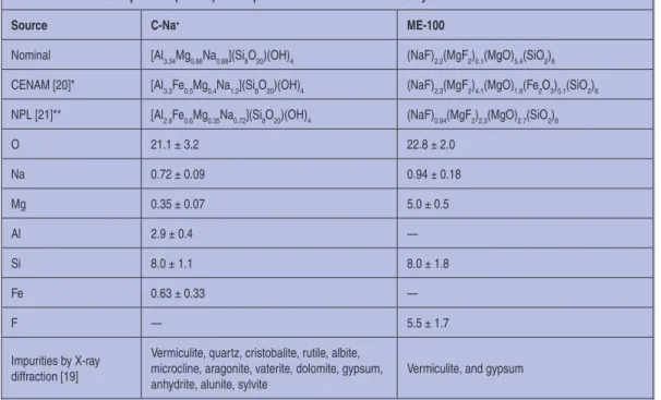
Table 2. Elemental Composition (in wt%) and Impurities of C-Na+ and ME-100 Clays.
Source C-Na+ ME-100
Nominal [Al3.34Mg0.66Na0.66](Si8O20)(OH)4 (NaF)2.2(MgF2)0.1(MgO)5.4(SiO2)8
CENAM [20]* [Al3.3Fe0.5Mg0.4Na1.2](Si8O20)(OH)4 (NaF)2.3(MgF2)4.1(MgO)1.8(Fe2O3)0.1(SiO2)8
NPL [21]** [Al2.9Fe0.6Mg0.35Na0.72](Si8O20)(OH)4 (NaF)0.94(MgF2)2.3(MgO)2.7(SiO2)8
O 21.1 ± 3.2 22.8 ± 2.0 Na 0.72 ± 0.09 0.94 ± 0.18 Mg 0.35 ± 0.07 5.0 ± 0.5 Al 2.9 ± 0.4 — Si 8.0 ± 1.1 8.0 ± 1.8 Fe 0.63 ± 0.33 — F — 5.5 ± 1.7 Impurities by X-ray diffraction [19]
Vermiculite, quartz, cristobalite, rutile, albite, microcline, aragonite, vaterite, dolomite, gypsum, anhydrite, alunite, sylvite
Vermiculite, and gypsum
ganic (e.g., humic substances), nonexpandable clays (e.g., amor-phous, vermiculite, kaolin), and diverse minerals (e.g., silica, feldspar, gypsum, orthoclase, apatite, halite, calcite, dolomite, quartz, biotite, muscovite, chlorite, and hematite) [1], [20].
Purification of natural clays into a polymer-grade material is a laborious, time consuming process involving hundreds of op-erations that finally result in sodium salt of clay containing less than about 5 wt% impurities, such as amorphous silicates, stacks of welded (by a crystallographic defect) platelets, and the re-sidual 0.3 to 2 wt% quartz particles with size exceeding 300 nm [24]. Purified clay also contains about 2 wt% of moisture and 7 wt% of material called “loss on ignition” comprising organics, hygroscopic and bound H2O, and carbonic acid [1], [25].
Table 2 lists impurities in natural (C-Na+) and semi-synthetic
(ME-100) clays. For the analysis of contaminants, clay was dis-persed in water and centrifuged. The sediment and solids recov-ered from the supernatant liquid were analyzed by X-ray dif-fraction.
Intercalants and Compatibilizers
The purified clays are in the form of sodium salts of plate-let stacks. They can be exfoliated in water or aqueous systems, forming thermodynamically miscible PNCs with water-soluble polymers. For dielectric applications, the polymers of choice are hydrophobic PO, which are thermodynamically immiscible with hydrophilic clays. The way out of this predicament is a two-step clay modification involving intercalation and compatibilization.
Intercalation involves replacement of Na+ by an organic
cat-ion, viz. ammonium or phosphonium. The most common are quaternary ammonium ions: R1R2R3R4N+ Cl− , where R
i is an
organic group. Their chemical character is selected on the basis of perceived miscibility with the polymer. For example, for PO
matrix, clay with di-methyl di-hydrogenated tallow quaternary ammonium chloride intercalant [Cloisite 20A, or C20A] might be used [1] (Figure 1).
The hydrogenated tallow contains a mixture of paraffinic chains: ~65% C18, ~30% C16, and ~5% C14. Intercalation not only changes the clay character (from hydrophilic to hydropho-bic), but also expands the intergallery spacing (i.e., between clay platelets in a stack) from about 1.2 nm up to 3 nm. The largest spacing is obtained using stoichiometric excess of intercalant with large molar volume. The expansion facilitates diffusion of macromolecular chains between clay platelets. Molecular simu-lation indicates that the ionic charge is delocalized on the clay surface and the intercalant is spread on it, covering its surface. Its structure is controlled by the concentration ratio of clay to intercalant [26].
The second step in the modification of a polymer/clay system is compatibilization. This is performed by incorporation of po-lar-group terminated macromolecules added to the polymer plus preintercalated clay during melt compounding. The theory of compatibilization was developed by Balazs and her colleagues [27]–[29].
Experimental
Compounding
The three principal methods for PNC preparation or com-pounding are (in order of historical importance):
• Reactive(in situ polymerization) by polymer manufac-turers,
• Solution(dispersingorganoclayinapolymersolution or emulsion), and
• Meltcompoundingbypolymercompoundersandplas-tics manufacturers.
Polypropylene has been used as a dielectric material in power capacitors and cable wraps, as well as in layer and phase sepa-rators for rotating electrical equipment and transformers [30], [31]. It has excellent properties, viz. outstanding resistance to moisture and oils, does not have stress-cracking problems, and offers good resistance at higher temperatures. The question is whether incorporation of clay platelets could improve the di-electric performance or not.
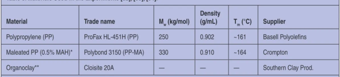
The three basic components of the formulation are listed in Table 3. Anhydride grafted polypropylene, Polybond 3150 (PP-MA), was used as a compatibilizer. The nanofiller was organi-cally modified MMT, C20A, shown in Figure 1.
Figure 1. Chemical structure of 2M2HT intercalant, di-methyl di-hydrogenated tallow, quaternary ammonium ion.
Table 3. Materials Used in the Experiments [32], [33], [34].
Material Trade name Mw (kg/mol)
Density
(g/mL) Tm (°C) Supplier
Polypropylene (PP) ProFax HL-451H (PP) 250 0.902 ~161 Basell Polyolefins
Maleated PP (0.5% MAH)* Polybond 3150 (PP-MA) 330 0.910 ~164 Crompton
Organoclay** Cloisite 20A — — — Southern Clay Prod.
*Polybond 3150 is PP grafted with 0.5 wt% of maleic anhydride (MAH) groups. **Cloisite 20A is MMT intercalated with methyl di-hydrogenated tallow ammonium chloride containing 38 wt% of organic phase, 2 wt% water; its nominal interlayer spacing is 2.47 nm.
10 IEEE Electrical Insulation Magazine Profiting from years of experience, the master batch method
of compounding was selected [32]. Thus, PP with 20 wt% PP-MA compatibilizer was dry blended and fed from a hopper with antioxidant (Irganox B-225 from Ciba), while 10 wt% of organ-oclay was supplied from a side feeder. The compounding was carried out at 200°C, screw speed of 200 rpm and throughput, Q = 5 kg/h (under blanket of dry N2) using a corotating twin-screw extruder. The extrudates were pelletized for use in the next step (dilution), which reduced the organoclay concentration to 0, 1, 2 and 4 wt%. The compatibilizer content was kept at a constant 2:1 ratio with respect to C20A.
Formation
The pelletized, dried compositions were film blown at T = 180°C to 230°C into 135-µm-thick films. Subsequently, the films were rolled twice at 115°C in a 3-roll calender to obtain the test samples.
Clay Dispersion
The interlayer spacing, d001 (basic spacing in clay stacks), was measured by the X-ray diffraction method. In addition, field emission gun scanning electron microscopy was used to observe the microdispersion in the film test samples. The direct observa-tion of exfoliated platelets in PNCs was conducted in a transmis-sion electron microscope.
As frequently reported, the d001 spacings for clay dispersion in isotactic PP is small, d001 = 3.00 to 3.72 nm, decreasing with concentration. Furthermore, the intercalated platelets form short stacks; thus the desired random dispersion of exfoliated platelets is not achieved. One of the reasons for this is crystallization of PP, which concentrates clay platelets in the amorphous regions, where the high concentration causes clay overcrowding and re-duction of d001.
It is known that the degree of clay dispersion depends on concentration; only at low concentration may the clay platelets freely rotate and thus achieve full exfoliation and random orien-tation. As the concentration increases above the encompassed volume packing fraction, clay platelets are forced to adopt local parallel orientation with spacing decreasing with concentration [1]. Some years ago a similar behavior was observed for con-stant clay content, Cclay, but a variable degree of crystallinity, X (%). Observations under electron microscope demonstrated that the clay stacks are located in the noncrystalline phase, indicat-ing that durindicat-ing crystallization the exfoliated or not clay platelets are expelled from the crystalline lamellae, increasing their lo-cal concentration in the amorphous phase. All of this led to the simple model of the interlayer spacing dependence in semicrys-talline polymers, which is a linear relationship [35]:
d001, calc(nm) = a0− a1Cclay− a2 X, (1) where a0 = 10.50 ± 0.64 nm, a1 = 0.392 ± 0.046, and a2 = 0.111 ± 0.011 are parameters, a0 being the interlayer spacing extrapo-lated to infinitely diluted CPNCs in amorphous PP. Thus, indeed exfoliation is expected in the amorphous PP.
Clay Effects on PNC Performance
Polymeric nanocomposites are used as either functional or structural materials. The functional ones are used in applications where a specific functionality is required, e.g., electrical con-ductivity or semiconcon-ductivity, magnetic properties, or biocom-patibility. The functional PNC contain expensive nanoparticles (e.g., carbon nanotubes or spherical nanoparticles) and are pre-pared in small quantity under strictly controlled conditions. By contrast, the structural PNC with 2 to 5 wt% clay are consumed in large volume with 10 to 15% higher cost than the matrix poly-mer. Although the dielectric properties in a variety of electrical applications are of principal interest, the polymeric part must also show an appropriate balance of properties. Different sets of properties are required for capacitors or rotor windings than for outdoor applications as insulators or coatings.
The main advantages of the clay-containing PNC include improved mechanical performance (at 5 wt% clay loading, the tensile modulus increases by a factor of two), reduction of gas and vapor permeability (by a factor of 100 at 10 wt% loading), and reduction of flammability [1].
Mechanical Properties
The mechanical properties of polymers and their composites may be summarized by three quantities: tensile modulus, E; the strength, σ; and the Izod impact strength at room temperature,
NIRT.
For polymeric composites, the Halpin-Tsai derived expres-sion for relative modulus, ER, in the stress direction is [36]
E
R ≡ Ec/Em = (1 + 2pκφf)/(1 − κφf)
κ = (Er − 1)/(Er + 2p); Er ≡ Ef/Em, (2) where φ is the volume fraction, φm = 1 − φf; subscripts c, m and f stand for composite, matrix, and filler, respectively; and p is the aspect ratio. Accordingly, addition of filler particles increases ER when p, Ef, and φf increase. However, at low filler loadings as in CPNCs, ER linearly increases with φf:
ER ≈ 1 + aEφf, (3) where aE is a gradient increasing with Er. In other words, it is more difficult to increase the modulus of a rigid polymer (e.g., a glassy one) where the value of Ef is close to that of Em than that of a soft one (e.g., rubber) [37]. For the PP + PP–MA with 2 wt% organoclay (Ef= 170 GPa and p = 295), Equation 2 correct-ly predicts the measured value for CPNC: E= 2.4 ± 0.2 GPa.
The tensile strength, σ, for PNC depends on concentration, degree of exfoliation, type of bonding between clay platelets and the matrix, and compatibilizers. In two-component systems with particles perfectly adhering to the matrix, σ in the stress direc-tion is expected to follow the volumetric rule of mixtures [38]:
σc= σmφm+ σfφf σr≡ σc/σ
m= 1 + φf(σR − 1)
Taking the tensile strength of clay platelets, σf = 240 MPa [39], the relative tensile strength calculated from Equation 4 was significantly smaller than that measured (by a factor of about 5 for the PP-based PNC).
An explanation for this unexpected observation is found in the well-documented physico-sorption of macromolecules on the clay surface. The high surface energy of crystalline solids causes adsorption and immobilization of molecules on the sur-face [40], [41]. The thickness of the solidified layer on each side of a clay platelet ranges from 3 to 6 nm; thus the solid content in a PNC is that of clay multiplied by a factor of 9 to 13. Substitut-ing the experimental values into Equation 4 yields the effective volume fraction of the reinforcing filler, from which one may find that the bulk-average thickness of the adsorbed polymer layer is about 3 nm. It is noteworthy that the effect of increased volume fraction does not affect the modulus. The reason is that adsorption reduces the mean value of the filler particle modu-lus and its aspect ratio, compensating for the increased volume [42].
For most materials, increased stiffness (modulus) increases brittleness; hence NIRT ∝ 1/E. However, for the PP-based PNC, addition of compatibilizer (e.g., PP-MA) is a must. Because the compatibilizer has lower molecular weight and crystallinity, it may act as a toughening agent. As a consequence, these PNCs are formed by addition of clay, which increases stiffness, and ad-dition of compatibilizer, which increases toughness. Selection of the two ingredients and their concentration may engender PNC with higher modulus and NIRT at the same time [1].
Degradability
The undesirable changes of polymer properties during pro-cessing and use of polymeric articles are lumped together under the term degradability. There are many aspects of the process, some physical, viz., shearing, temperature, irradiation, and some chemical caused by the presence of transition metal ions (e.g., manganese, iron, cobalt, nickel, or copper), which catalytically accelerate degradation. For the present discussion, the second aspect, the degradability during the lifetime of the CPNC arti-cle, is important. The main question is how the presence of clay, the intercalant and compatibilizers that come with it, affects the polymeric matrix stability. To narrow the discussion, only PO/ clay systems will be considered.
The onset of thermal instability of organoclays has been re-ported as low as 135°C. Two aspects need to be considered: (1) the type of intercalant and (2) the quality of clay. The predomi-nant type of organoclay is MMT intercalated with a long-chain aliphatic quaternary ammonium cation. The stability of organo-clay is improved by the reduction of the degree of substitution and the use of branched paraffinic substituents. Thus, the thermal stability improves in the sequence RiH3N+ > R
i2H2N + >R
i3HN + >
Ri4N+ and when straight paraffinic chains, viz., R(CH 2)n-N
+, are
replaced by the branched ones, e.g., RC(CH3)2CH2-N+ [1].
As discussed in Characterization of Clay Platelets, the chemi-cal composition of natural MMT varies with geographichemi-cal loca-tion and mine strata. Some clays (e.g., from Wyoming) contain Fe+3 ions (Fe
2O3 content of 3.6 wt%), which through catalytic
activity affect CPNC weatherability and thermal stability.
Fur-thermore, these clays with large surface areas adsorb polar mol-ecules such as antioxidants, stabilizers, and others, increasing the vulnerability of the polymer matrix. For these reasons there is a growing list of chelating metal scavengers that dramatically stabilize the PNC [43], [44]. Thus, the inherent problems associ-ated with thermo-oxidative sensitivity of clays, intercalants, and compatibilizers may be eliminated by judicious selections and stabilization, resulting in CPNC with high thermal and photo-oxidative stability, sometimes better than that of a neat resin [45], [46].
Some compatibilizers used in PP-based PNC may contain unsaturations (e.g., double bonds in the maleated ethylene-propylene-rubber). The unsaturations are responsible for rapid oxidative degradation, catalyzed by UV, light, and heat. It is noteworthy that rubbers require 10 times more stabilizer that do plastics [47].
The stabilizing clay effects on polymers often originate in the surface enrichment of clay concentration observed during the thermal, photo-oxidative, and flame retardance tests. As the out-er polymout-eric layout-er decomposes, the clay platelets are left behind, slowing the diffusion of the degradation products by creation of a dense platelet network or char. In all three cases there is sig-nificant slowing down of the degradative process. For example, in PNC with 2 to 8 wt% of clay, the flammability was reduced by 50 to 80% (as measured by peak heat release rate) without reduction of physical properties (that take place upon addition of standard flame retardants) or increase of smoke [48], [49].
Dielectric Properties of PNC [33], [34], [50]–[52]
Several dielectric tests have been carried out on PP-based PNC, taking into account the short-term electrical aging effects, e.g., breakdown strength (EBD), dielectric loss at power frequen-cy, electroluminescence emission (EL), space charge distribu-tion, and partial discharge erosion (PDE) depth measurements.
Significant differences in dc and ac were observed [33], [34], [50]. Adding organoclay to PP increased the dc breakdown strength, e.g., with 2 wt% clay loading, from 350 to 380 kV/mm. Slightly lower ac and dc breakdown strengths were obtained for PP with higher clay content (4 wt%). A significant effect of the clay presence on the loss tangent (Tanδ) and capacitance (Cp) is evident from data in Table 4. Within the employed concentration range, the increases are linear, viz.:
Tanδ = 1.13 + 10.2w, r = 0.998;
and Cp = 125 + 5.84w, r = 0.981, (5) where w is organoclay content in wt% and r is the correlation coefficient. The polar species (i.e., ionic organoclay and the
par-Table 4. Tanδ and Capacitance of PP-Based PNC at 15 V, 60 Hz [33]. PNC (PP-wt% clay) Tanδ (10−4) Capacitance, Cp (pF)
PP-0 1.88 123.3
PP-2 20.1 139.0
12 IEEE Electrical Insulation Magazine tially hydrolyzed PP-MA) increase the loss factor and
conduc-tivity of CPNC.
Electroluminescence emission (EL) from samples subjected to ac voltage under uniform field geometry was measured in the photon counting mode, increasing the electric field from 0 to 40 kV/mm in steps of 2 kV/mm. Addition of organoclay to PP did not affect the EL inception field, E0 = 18 kV/mm, but it dramati-cally changed the EL increase with voltage, viz., incorporation of 2 and 4 wt% organoclay reduced the number of EL pulses (in thousands, kp) at 40 kV/mm from 93 to 28 and 18 kp, respec-tively.
The PNCs of similar composition to those listed in Table 3 have been used in the VAMAS coordinated round-robin tests of the electrical and dielectric properties [51], [52]. The earlier observations have been confirmed—dispersion of organoclay platelets improved the PP performance, but one laboratory re-ported the ac breakdown strength (BD) of PP as 120 kV/mm increasing linearly with organoclay concentration to 132 ± 4 kV/ mm (at 6 wt% organoclay), whereas another laboratory reported
BD increased from 131 to 160 kV/mm. However, it is notewor-thy that the modest positive effect of nanofiller addition is in sharp contrast with a large reduction in performance produced by incorporation of microfillers.
Another industrially important effect of clay addition is a vir-tual arrest of PP aging. Similarly, a prominent effect was evident in the space charge effects—the accumulated charge in PNCs with 2 wt% organoclay started decreasing after 240 h of aging, whereas that in PP continued to increase with aging time t ≤500 h reaching the charge value 2.5 times larger than that in PNC.
A PDE test was carried out at 2 or 5 kVrms, 600 Hz with a tungsten rod electrode, with a 200-µm air gap. After 120 h of testing, the PP matrix and CPNC containing 2 and 6 wt% organ-oclay showed erosion depths of 44 ± 14, 22 ± 11, and 21 ± 3 µm, respectively. Apparently, the initial vaporization of PP increased the clay concentration on the surface to a similar level, virtually independent of the initial clay content. Thus, the presence of ≤2 wt% organoclay reduced the PDE depth by about 50%. The initial rate of erosion in the partial discharge test for PP was 1.26 mm/C, and that for PP with 6 wt% organoclay was about nine times smaller, viz., 0.14 mm/C [52].
Schönhals determined the dielectric behavior of PP-based PNCs with 0, 2, and 6 wt% of organoclay as a function of tem-perature (T) and frequency (ν) [53]. In accord with the previous observations, he reported that the dielectric loss increases with clay content, as does the permittivity at low frequency. The in-crease in dielectric loss is caused by inin-creased conductivity and Maxwell/Wagner/Sillars polarization changes with temperature and frequency, caused by blocking of the charge carriers by clay platelets and their double layers.
Bulinski et al. reported on the dielectric behavior of PP-based CPNCs containing 0, 2, 4, and 8 wt% of fully synthetic organo-clay [54], [55]. The ingredients of composition of the PNCs were similar to those in Table 3, and the method of compounding and forming was as described above. The fully synthetic organoclay was Topy 4CD-Ts, tetrasilisic fluoro-mica, NaMg2.5Si4O10F2, preintercalated with di-methyl di-stearyl ammonium chloride [5]. In contrast with the natural clay in Table 3, the synthetic clay
does not contain mineral contaminants, is more hydrophobic, and has a platelet aspect ratio of p <6,000 (instead of 280).
Charge injection in these samples was initiated at the same value of the electric field, but the electroluminescence and dissi-pation current measurements showed that the amount of charge injected into the PNCs during aging was less than that into PP. Thus, after prolonged aging at −40 kV, there was only a slight increase in the amount of charge accumulated in the nanodielec-trics as compared with PP. This suggests that these PNCs might be useful for such devices as high voltage capacitors and trans-formers that operate at high electric fields.
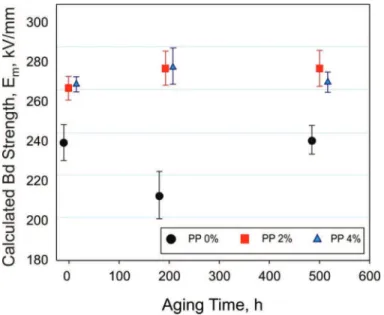
Figure 2 displays the breakdown test results for the PP-based PNC containing 0, 2, and 4 wt% synthetic organoclay. The breakdown strength, Em, was calculated according to the Mason method, thus eliminating the effects of surface discharge in oil [56]. The addition of organoclay to PP resulted in a moderate (by ca. 12%) increase in ac breakdown strength. Aging at 90°C in a dc field of 40 kV/mm for up to 500 h did not reduce the breakdown strength of the nanocomposites.
The addition of organoclay also increased the dielectric loss factor over broad frequency and temperature ranges. Again, ag-ing the PNC samples did not significantly change the behavior. Charge trapping at the nanofiller particle/polymer matrix inter-faces is the most likely cause. The dc conductivity of PNCs was higher than that of PP, most likely because of the overlapping of the ionic layers surrounding the clay particles. Aging the PNCs in dc fields resulted in a smaller increment of the dc conductivity than that of PP.
Summary and Conclusions
This article is an attempt to answer several questions listed in the Introduction. Therefore, it is logical that this final part should
Figure 2. Effect of aging at 90°C in a dc field of 40 kV/mm on breakdown (Bd) strength of PP-based PNC containing 0, 2, and 4 wt% synthetic organoclay. The experimental error bars indi-cate 95% confidence intervals [50].
attempt to answer some of these on the basis of the described procedures and test results.
Re 1. PNC Components and Composition
Chemically, there is a large difference between the two prin-cipal components of CPNCs: the polymeric matrix and clay platelets. The polymers of interest, PE or PP, are hydrophobic hydrocarbon macromolecules, thermodynamically immiscible with the hydrophilic silicate. The two-step compatibilization creates a diffused ionic layer around the clay platelet, with addi-tional ion clusters dispersed in the matrix. The interface between clay and matrix is further complicated by the physico-sorption of organic molecules (e.g., the matrix polymer) and its solidifi-cation, increasing the effective clay solid content. Clay is an effi-cient nucleating agent for polymeric matrix, which may increase its crystallinity. However, depending on the type and amount of intercalant, the intercalation may prevent this effect.
Re 2. Preparation of PNCs
Preparation of PNCs is a common practice in laboratories and in the plastics industry. The methods of compounding are well established. However, they rarely lead to full exfoliation in semi-crystalline, hydrophobic matrices such as PP. What we see in the high-resolution transmission electron microscope is a large number of exfoliated single clay platelets and at the same time stacks and aggregates. The performance depends on the relative quantity of these two clay dispersions.
The specimens used in this study were formed using stan-dard processing equipment in a general pilot plant, not in a fa-cility designed to produce dielectric films with precise control of purity and dimensions. However, because such facilities and procedures are known in the industry, production of CPNCs for dielectric application is not expected to cause undue problems.
Re 3. Properties of CPNCs
Evidently, the properties of CPNC depend on composition, thus polymeric matrix, type of clay, type of intercalant and com-patibilizer, as well as composition. In the second line, the critical parameters for performance are the morphology, including dis-persion and 3-D orientation of clay platelets. For the long-term properties, stability is critical, which also depends on compo-nents, their protection by addition of stabilizers, and abuse dur-ing compounddur-ing and formdur-ing.
It was not mentioned in the experimental part, but the compo-sition in Table 3 is a result of a long process of trials of various grades of PP, organoclays, and compatibilizers. For example, PP has low strain hardening behavior in elongational flow that makes film blowing difficult. The organoclays often contain ex-cess intercalant, which increases interlayer spacing but at the same time reduces the thermal stability and increases the amount of contaminating low-molecular-weight species. The compatibi-lizing maleated-PP is inefficient if the number of maleic groups is small, but it becomes immiscible with the matrix if it is too high (the phase separation forms ionic clusters dispersed in the PP matrix). Luckily, there are mathematical models that may help in selecting the best compatibilizer and concentration.
As mentioned in the text, full exfoliation of clay platelets is feasible only at low concentration, at which the individual clay platelets can freely rotate in 3-D space. For the most common organoclay based on Wyoming clay, e.g., Cloisite 20A, this limiting concentration is 1.14 wt%. Above this limit platelets will form local stacks of decreasing interlayer spacing. The next critical concentration is about 3.6 wt%, at which the stacks with solidified matrix layer around them will fill the whole CPNC volume. Thus, addition of a further amount of organoclay will only enrich the PNC in clay stacks having the same interlayer spacing as in the organoclay. In consequence, the usual upper limit of clay content in commercial CPNCs is 5 wt%—within the concentration range of 2 to 5 wt% organoclay, various prop-erties reach their maxima.
In the text, two types of CPNC with natural and synthetic clays were discussed, viz., Cloisite 20A (MMT) and the syn-thetic tetrasilisic fluoro-mica (FM), respectively. Considering the difference in purity, the aspect ratio, and the clay chemis-try, it was expected that CPNC with FM should show superior performance over that with MMT. Experimentally, for CPNC the short-term ac breakdown strength and resistance to partial discharges was virtually identical, independent of the clay type. Specimens based on FM showed a narrower distribution of the times to breakdown under partial discharges than the specimens containing MMT. Both clays increased dielectric losses of PP especially at higher frequencies and temperatures. However, CPNC with MMT had losses nearly one decade higher than that of specimens containing FM. Thus, type of clay influences some dielectric properties but not others.
In general, dispersion of the small amount of organoclay had a moderate effect on dielectric properties—the performance improved with the degree of dispersion. However, the clay ef-fect on aging in dc field was significant—addition of 2 wt% of organoclay reduced the matrix aging effect by a factor of two. Similarly a large effect was observed in the PDE test during which the depth in neat PP was halved by incorporation of 2 wt% organoclay.
It is evident that incorporation of clay affects other PP prop-erties. For example, the modulus of CPNCs (e.g., based on PO or polyamide) increases at a rate of 20% per 1 wt% of added clay. Their tensile and impact strength depends on the type and amount of compatibilizer; independently of the modulus, the two other properties may increase or decrease from the matrix level. The CPNCs show reduced diffusion of gases or vapors, UV degradability, weatherability, and flammability of the matrix polymer. For dielectric applications, these benefits are coming as a premium.
Acknowledgments
The author wishes to acknowledge with thanks the encour-agements, collaboration, and help by Alexander T. Bulinski and his colleagues from the NRCC/INMS in Ottawa, Soli Bamji and Mahmoud Abou-Dakka.
References
[1] L. A. Utracki, Clay-Containing Polymeric Nanocomposites, Shawbury, Shrewsbury, Shropshire, UK: RAPRA, 2004.
14 IEEE Electrical Insulation Magazine
[2] S. S. Ray and M. Bousmina, Polymer Nanocomposites and Their
Applica-tions, Valencia, CA: American Scientific Publishers, 2006.
[3] J. H. Koo, Polymer Nanocomposites, New York, USA: McGraw-Hill Professional, 2006.
[4] R. K. Gupta, E. Kennel, and K.-J. Kim, Polymer Nanocomposites
Hand-book, Boca Raton, FL: CRC Press, 2009.
[5] L. A. Utracki, M. Sepehr, and E. Boccaleri, “Synthetic, layered nano-particles for polymeric nanocomposites PNC’s,” Polym. Adv. Technol., vol. 18, pp. 1–37, 2007.
[6] F. Annabi-Bergaya, “Layered clay minerals. Basic research and innova-tive composite applications,” Microporous Mesoporous Materials, vol. 107, pp. 141–148, 2008.
[7] C. Green and A. Vaughan, “Nanodielectrics—How much do we really understand? IEEE Electr. Insul. Mag., vol. 224, pp. 6–16, 2008. [8] L. A. Utracki, Ed., Polymer Blends Handbook, Dordrecht, The
Nether-lands: Kluwer Academic Pub., 2002.
[9] L. Nicolais and G. Carotenuto, “Metal particles confined in polymeric matrices,” in Polymer Physics, L. A. Utracki and A. M. Jamieson, Eds. New York, NY: J. Wiley & Sons, 2010.
[10] B. K. G. Theng, The Chemistry of Clay—Organic Reactions, New York, NY: J. Wiley & Sons, 1974.
[11] J. K. Orlemann, “Process for producing synthetic hectorite-type clays,” US Patent 3,666,407, 1972.
[12] H. Tateyama, K. Tsunematsu, K. Kimura, H. Hirosue, K. Jinnai, and T. Furusawa, “Method for producing fluorine mica,” US Patent 5,204,078, 1993.
[13] B. S. Neumann, “Synthetic hectorite-type clay minerals,” US Patent 3,586,478, 1971; US Patent 3,671,190, 1972.
[14] J. Jaffe, “Hydrothermal method for manufacturing a novel catalytic mate-rial, catalysis containing said matemate-rial, and process using said matemate-rial,” US Patent 3,803,026, 1974.
[15] N. Daimon and T. Izawa, “Sol of ultra-fine particles of synthetic hecto-rite,” US Patent 3,936,383, 1976.
[16] Y. Zhao, F. Li, R. Zhang, D. G. Evans, and X. Duan, “Preparation of lay-ered double-hydroxide nanomaterials with a uniform crystallite size using a new method involving separate nucleation and aging steps,” Chem.
Mater., vol. 14, pp. 4286–4291, 2002.
[17] “Perkalite® processing in polyolefins,” Akzo Nobel Polymer Additives, Technical Bulletin PA 07.415.01, June 2007.
[18] K. A. Carrado, “Synthetic organo- and polymer-clays: Preparation, characterization and materials applications,” Appl. Clay Sci., vol. 17, pp. 1–23, 2000.
[19] F. Perrin-Sarazin and M. Sepehr, “Determination of shape size and size distribution of nano-filler particles,” Test Procedure for VAMAS TWA-33,
Project #1, Montreal, Canada, 2007.
[20] J. L. Cabrera-Torres, F. Rosas-Gutierrez, E. Ramirez-Maldonado, J. M. Juarez-Garcia, and N. Gonzalez-Rojano, “Report on the determination of shape size and size distribution of nano-filler particles,” Centro Nacional de Metrologia, Mexico, Aug. 2009.
[21] W. Broughton, “Chemical analysis of clay by EDX,” NPL Report, Ted-dington, UK, Sept. 2009.
[22] V. A. Drits, Structural and chemical heterogeneity of layered silicates and clay minerals, Clay Minerals, vol. 38, pp. 403–432, 2003.
[23] G. Lagaly and S. Zismer, “Colloid chemistry of clay minerals: The coagulation of montmorillonite dispersions,” Adv. Colloid Interface Sci., vol. 100-102, pp. 105–128, 2003.
[24] M. Clarey, J. Edwards, S. J. Tsipursky, G. W. Beall, and D. D. Eisenhour, “Method of manufacturing polymer-grade clay for use in nanocompos-ites,” US Patent 6,050,509, 2000.
[25] Standard Test Methods for Loss on Ignition LOI of Solid Combustion Residues, ASTM D7348 – 08, 2008, updated Dec. 1, 2009.
[26] G. Tanaka and L. A. Goettler, “Predicting the binding energy for nylon 6,6/clay nanocomposites by molecular modeling,” Polymer, vol. 43, pp. 541–553, 2002.
[27] A. C. Balazs, C. Singh, and E. Zhulina, “Modeling the interactions between polymers and clay surfaces through self-consistent field theory,”
Macromolecules, vol. 31, pp. 8370–8381, 1998.
[28] A. C. Balazs, C. Singh, E. Zhulina, and Y. Lyatskaya, “Modeling the phase behavior of polymer/clay nanocomposites,” Acc. Chem. Res., vol. 32, pp. 651–657, 1999.
[29] K. Kim, L. A. Utracki, and M. R. Kamal, “Numerical simulation of
poly-mer nanocomposites using a self-consistent mean-field model,” J. Chem.
Phys., vol. 121, pp. 10766–10777, 2004.
[30] M. Rabuffi and G. Picci, “Status quo and future prospects for metalized polypropylene energy storage capacitors, IEEE Trans. Plasma Sci., vol. 3, pp. 1939–1942, 2002.
[31] E. Ildstad and T. Haave, “Conduction and partial discharge activity in HVDC cable insulation of lapped polypropylene films,” IEEE 7th Int.
Conf. Solid Dielectr., 2001, pp. 137–140.
[32] J. Li, M.-T. Ton-That, W. Leelapornpisit, and L. A. Utracki, “Melt compounding of polypropylene-based clay nanocomposites,” Polym. Eng.
Sci., vol. 47, pp. 1447–1458, 2007.
[33] S. S. Bamji, M. Abou-Dakka, A. T. Bulinski, L. Utracki, and K. C. Cole, “Dielectric properties of propylene containing nano-particles,” Proc. 74th
IEEE Conf. Electr. Insul. Dielectr. Phenom. CEIDP, 2005, pp. 166–170. [34] S. S. Bamji, M. Abou-Dakka, A. Bulinski, and L. A. Utracki, “Electrolu-minescence and space charge in nanodielectrics subjected to AC voltage,”
J. Central Power Res. Inst., Bengaluru, India, vol. 4, no. 2, pp. 185–194, Sept. 2008.
[35] M.-T. Ton-That, W. Leelapornpisit, L. A. Utracki, F. Perrin-Sarazin, J. Denault, K. C. Cole, and M. N. Bureau, “Effect of crystallization on intercalation in clay-polyolefin nanocomposites and their performance,”
Polym. Eng. Sci., vol. 46, pp. 1085–1093, 2006.
[36] J. C. Halpin, Primer on Composite Materials Analysis, 2nd ed., Lan-caster, PA: Technomic Publ. Co., 1992.
[37] L. A. Utracki, “Mechanical properties of clay-containing polymeric nanocomposites,” in Handbook of Polymer Nanocomposites, R. Gupta, E. Kennel, and K.-J. Kim, Eds., Boca Raton, FL: CRC Press, 2009. [38] N. G. McCrum, C. P. Buckley, and C. B. Bucknall, Principles of Polymer
Engineering, Oxford, UK: Oxford Sci. Pub., 1988.
[39] J. V. Milewski and H. S. Katz, Eds., Handbook of Reinforcements for
Plastics, New York, NY: Van Nostrand Reinhold Co., 1987. [40] G. Luengo, F.-J. Schmitt, R. Hill, and J. N. Israelachvili, “Thin film
rheology and tribology of confined polymer melts: Contrasts with bulk properties,” Macromolecules, vol. 30, pp. 2482–2494, 1997.
[41] R. Hentschke, “Molecular modeling of adsorption and ordering at solid interfaces,” Macromol. Theory Simul., vol. 6, pp. 287–316, 1997. [42] L. A. Utracki, M. Sepehr, and J. Li, “Melt compounding of polymeric
nanocomposites,” Inter. Polym. Process., vol. 21, pp. 3–14, 2006. [43] R. Pfaendner, “Nanocomposites: Industrial opportunity or challenge,”
presented at the MoDeSt-2008 5th Int. Conf., Liege, Belgium, Sept. 7–11, 2008.
[44] F. P. La Mantia, N. Tzankova Dintcheva, V. Malatesta, and F. Pagani, “Improvement of photo-stability of LLDPE-based nanocomposites,”
Polym. Degrad. Stab., vol. 91, pp. 3208–3213, 2006.
[45] N. Tz. Dintcheva, S. Al-Malaika, and F. P. La Mantia, “Effect of extru-sion and photo-oxidation on polyethylene/clay nanocomposites,” Polym.
Degrad. Stab., vol. 94, pp. 1571–1588, 2009.
[46] A. Leszczyńska, J. Njuguna, K. Pielichowski, and J. R. Banerjee, “Poly-mer/montmorillonite nanocomposites with improved thermal properties: Part I. Factors influencing thermal stability and mechanisms of thermal stability improvement,” Thermochim. Acta, vol. 453, pp. 75–96, 2007; “Part II. Thermal stability of montmorillonite nanocomposites based on different polymeric matrixes,” Thermochim. Acta, vol. 454, pp. 1–22, 2007.
[47] M. Chen, N.-J. Ao, Y.-Y. Liao, Y. Chen, and H.-L. Zhou, “Thermooxida-tive degradation of natural rubber/clay composite,” J. Appl. Polym. Sci., vol. 100, pp. 3809–3815, 2006.
[48] J. W. Gilman, T. Kashiwagi, A. B. Morgan, R. H. Harris, Jr., L. Brassell, M. Vanlandingham, and C. L. Jackson, “Flammability of polymer clay nanocomposites consortium: Year one annual report,” US Dept. Com-merce, Technology Administration, National Institute of Standards and Technology, Report NISTIR #6531, Gaithersburg, VA, 2000.
[49] J. Zhu, and C. A. Wilkie, “Flammability properties of polymer nanocom-posites,” in Handbook of Polymer Nanocomposites, R. Gupta, E. Kennel, and K.-J. Kim, Eds., Boca Raton, FL: CRC Press, 2009.
[50] A. Bulinski, S. S. Bamji, M. Abou-Dakka, and Y. Chen, “Dielectric prop-erties of polypropylene containing synthetic and natural organoclays,” in Proc. 2010 IEEE Int. Symp. Electr. Insul., San Diego, CA, June 6–9, 2010.
[51] A. Bulinski, S. S. Bamji, and M. Abou Dakka, VAMAS TWA-33, Project #2 Report, 2nd Annual Meeting, Rome, Italy, Aug. 30, 2009.
[52] N. Fuse, T. Tanaka, and Y. Ohki, “Evaluation of dielectric properties in polypropylene/clay nanocomposites,” 2009 Ann. Rep. IEEE Conf. Electr. Insul. Dielectr. Phenom., Virginia Beach, VA, Oct. 18–21, 2009. [53] A. Schönhals, “Dielectric relaxation of nanocomposites of polypropylene
and clay nanofillers,” 2nd Annual Meeting of VAMAS TWA-33, Rome, Italy, Aug. 30, 2009.
[54] A. Bulinski, S. S. Bamji, M. Abou Dakka, and Y. Chen, “Dielectric properties of polypropylene loaded with synthetic organoclay,” 2009 Ann. Rep. IEEE Conf. Electr. Insul. Dielect. Phenom., Virginia Beach, VA, Oct. 18–21, 2009.
[55] S. S. Bamji, A. Bulinski, and M. Abou-Dakka, “Space charge in polypro-pylene containing synthetic nano particles,” 2009 Ann. Rep. IEEE Conf. Electr. Insul. Dielect. Phenom., Virginia Beach, VA, Oct. 18–21, 2009. [56] J. Mason, “Effects of thickness and area on the electric strength of
poly-mers,” IEEE Trans. Elect. Insul., vol. 26, no. 2, pp. 318–322, 1991.
Leszek A. Utracki is a senior research
officer of the National Research Council of Canada, Industrial Materials Institute in Montreal. He was educated in Poland (Chem. Eng. in 1953, M. Eng., Dr. Tech, Sci., Habilitated Private Docent/Doctorat d’État in polymer physics). After a post-doctoral stage (1960–1962) at the Univer-sity of Southern California in Los Angeles, he was visiting professor at Case Western Reserve University in Cleveland, Ohio, and then carried out re-search in Canada at Shawinigan Chemicals, McGill University, and CIL Inc. He is author of 21 written or edited books, 48 book chapters, and over 270 articles in referenced, scientific journals. Two companies were created on the basis of his 15 patented in-ventions. He has been an adjunct professor at McGill Univer-sity and lecturing professor in the Americas, Europe, Asia, and Australia. He is cofounder and past-president of the Canadian Rheology Group and the Polymer Processing Society (Interna-tional).
![Table 4. Tanδ and Capacitance of PP-Based PNC at 15 V, 60 Hz [33].](https://thumb-eu.123doks.com/thumbv2/123doknet/14143307.470760/7.891.453.840.971.1083/table-tanδ-capacitance-pp-based-pnc-v-hz.webp)