Analysis and Comparison of Connections in Steel Structures
byLeigh Manson
B.S., Civil and Environmental Engineering University of Illinois at Urbana-Champaign, 2005
Submitted to the Department of Civil and Environmental Engineering in Partial Fulfillment of the Requirements for the Degree of
Master of Engineering in Civil and Environmental Engineering at the
Massachusetts Institute of Technology June 2006
C 2006 Massachusetts Institute of Technology. All rights reserved.
MASSACHUSETTS It OF TECHNOLC
JUN 0
7
20
LIBRARI
Signature of Author:...
Department of Civil and Environmental Engineering May 12, 2006 C ertified by:... P A ccepted by:... .... --... Jerome J. Connor rofessor o1Cigl and 1nvironmental Engineering Thesis Supervisor ---- ---Andrew Whittle Chairman, Departmental Committee for Graduate Students
NSTITUTE
IGY
06
ES
Analysis and Comparison of Connections in Steel Structures
byLeigh Manson
Submitted to the Department of Civil and Environmental Engineering on May 12, 2006 in Partial Fulfillment of the Requirements for the Degree of Master of Engineering in
Civil and Environmental Engineering ABSTRACT
The topic of connections is often given only limited attention in structural analysis and design of buildings, despite the fact that they can play a critical role in the structure. It is customary practice in the U.S. for the structural engineer to design the structural
members, but leave the connection details to the steel fabricator. While this practice is more efficient and pragmatic in some instances, it is also necessary for structural engineers to have a good knowledge of connection behavior, especially when dealing with newer or atypical connections. Both the theoretical modeling of connections and the physical geometry and components of connections are considered in this thesis.
For the theoretical modeling of connections, the concept of semi-rigid connections as an alternative to the conventional idealizations of perfectly pinned or rigid connections will be addressed. Included will be methods to model and design semi-rigid connection behavior within frames. The effects of connection behavior on frames will also be considered.
With regard to the physical components of connections, an overview of types of fasteners and joints will be presented, including types and methods of installing bolts and welds, shop-welded, field-bolted column trees, and comparisons between these options. A final section presents options for connections between hollow structural sections of both circular and rectangular cross sections.
Finally, the topics covered for connections will be applied to the design project for the MIT class 1.562 as part of the MEng program in high performance structures.
Thesis Supervisor: Jerome J. Connor
TABLE OF CONTENTS
1. INTRODUCTION TO CONNECTIONS IN STEEL BUILDINGS...4
1.1 CONNECTION DESIGN METHODS... 4
1.2 CHARACTERIZATION OF CONNECTIONS ... 6
1.2.1 IDEALIZED PINNED AND MOMENT CONNECTIONS ... 6
1.2.2 SEM I-R IGID C ONNECTIONS... 7
1.3 CONNECTIONS IN A FRAME ... 8
2. SEMI-RIGID CONNECTIONS AND FRAMES ... ... 9
2.1 THE MOMENT-ROTATION RELATIONSHIP... 11
2.1.1 MODELING THE MOMENT-ROTATION CURVE ... 12
2.1.2 CLASSIFICATION OF CONNECTIONS BY RIGIDITY... 13
2.2 DESIGN OF SEMI-RIGID STRUCTURES ... 16
2.2.1 MOMENT DISTRIBUTION METHOD FOR SEMI-RIGID DESIGN ... 16
2 .2 .2 F R A M E D ESIG N ... 19
2.2.3 STABILITY DESIGN OF SEMI-RIGID FRAMES ... 20
2.2.4 STRUCTURAL COMPUTER MODELING OF SEMI-RIGID BUILDINGS... 21
3. STRUCTURAL CONNECTIONS... 26
3.1 PINNED AND FIXED CONNECTIONS ... 26
3.2 SEMI-RIGID CONNECTIONS...27
3.3 WELDED JOINTS... ... ... 28
3.4 BOLTED JOINTS... o... ... ... 29
3.5 FAILURE OF CONNECTIONS... 32
3.6 COMPARISON AND CHOICE OF JOINTS... 33
3.7 COLUM N TREES...34
4. CONNECTIONS FOR HOLLOW STRUCTURAL SECTIONS... 37
4.1 TYPES OF CONNECTIONS... ... 38
4.2 STRENGTH OF CONNECTION ... 39
4.2.1 W ELD ED JO IN TS... 4 1 4 .2 .2 B O LTED JO IN TS ... 42
4.3 CONNECTION DETAILS FOR RHS... 44
5. APPLICATION OF STUDY OF CONNECTIONS TO MENG COURSE 1 FORT POINT CHANNEL PROJECT ... 46
5.1 REPAIR AND REHABILITATION OF OLD NORTHERN AVENUE BRIDGE ... 46
5.2 CIRCULAR HOLLOW SECTION CONNECTIONS FOR MARITIME MUSEUM PROPOSAL ... 50
1. Introduction to Connections in Steel Buildings
Most design tasks in structural engineering are based both on theoretical models and empirical evidence. The theory is developed into a design procedure, and this procedure is carried out and tested. The results of these tests are then used to formulate new and more accurate analysis procedures. So, to some extent, this is an iterative process. Centuries of experience with building structures as well as new developments in
analytical procedures have led to a greater understanding of how structures work. This is especially true in the area of connections in structures. There is a fairly high degree of uncertainty in the behavior of connections, which makes their analysis and design
difficult, and makes experimental verification so important. Many of the elements of the connections have variability in their properties, which, when analyzed together, further increase the uncertainties in the connection. The consequence of this is that careful and accurate design of connections can be crucial to the design of the structure. This thesis attempts to understand and compare various types of connections in structural steel buildings, including both the modeling theory of connections as well as the physical components of connections.
1.1 Connection Design Methods
In the United States, a typical design engineer specifies the loads to be transferred through the connection, but does not design the connection completely. The steel
fabricator is responsible for designing the exact location, number, and type of bolts and welds, producing shop drawings with connection details. The design engineer then checks these shop drawings. In many ways this is the most practical and efficient method of design, but in some ways it might be beneficial for structural engineers to have a greater understanding of connections. The general design procedure which structural engineers use can be summarized in four essential steps:
1. Calculate the distribution of forces within the connection.
This calculation starts with a determination of the distribution of forces within the elements to be connected. For beams carrying shear and moment, it is almost always assumed that the beam web carries the shear force while the
flexibility of the parts of the connection are assessed. The flexibility is important for determining the flow of forces within the connection.
2. Design the components of the connection such that the each force path has the required strength to transmit the forces.
3. Ensure adequate ductility in the connection. This amounts to taking
compatibility into account, because the above steps account only for force equilibrium.
4. Check that serviceability requirements are met. Also check other factors such as fatigue resistance, fracture for welds, and corrosion protection.
According to one evaluation, "This is self-evident, and yet it is surprising how frequently designers leave a weak link somewhere in a connection" [4]. There are a number of possible reasons for this omission. One possible source is that designers sometimes use more than one analysis to determine the distribution of forces. For example, when both welds and bolts are present in a beam, many sources recommend against looking at these connections separately. A more preferable method is to determine the most critical part of the connection, and then use this to determine the forces in other elements of the connection. Another possible source of error in connection design comes from lack of experience. Because connection design does depend so heavily on learning from past experiences and test results, inexperienced engineers can sometimes naively follow code guidelines without regard to common practices and history. And finally, another major
source of error is that codes often focus on the actual connector strength, such as the bolt or weld strength, without focusing on other factors, such as the plates or angles which connect the members, and construction procedures. [4]
One of the most interesting facts about the design of structural connections is that, in practice, many checks are not actually carried out. "Most connection design is very
straightforward and satisfies the preceding criteria by implication rather than by specific calculation." [14]. The elements of the connection, such as geometry, bolt spacing, types of bolts, and weld geometries are often determined such that these checks are not
required. The assumption, then, is that these requirements have already been met. By designing the geometry of the connection to meet, for example, code requirements on minimum edge distance between the bolt and the plate, or by using symmetrical
connections, an exact structural analysis is not actually carried out. Furthermore, often heuristic methods are used, without a true understanding of why these guidelines work.
For example, plate thickness might be designed to be a certain percentage of the bolt diameter. While in most cases these simplifications and guidelines are quite acceptable, it does not help engineers gain experience and develop a full understanding of
connections, which could be detrimental when it comes to more irregular structures, such as hollow sections, eccentric loadings, or fatigue-critical zones. For this reason a greater focus on connections in academia and in practice may be very beneficial to structural engineers.
1.2 Characterization of Connections
Connections are classified by their strength as well as their ductility, where ductility is a description of the rotation capacity. The strength classification of
connections is based on the relative moment resistance of the connection compared to the moment resistance of the beam. A full strength connection has a strength that is greater than the plastic moment capacity of the beam. Both strength and rotation capacity are essential for the connections. To illustrate the importance of both strength and rotation capacity in connections, full-strength connections designed by plasticity theory can be considered. In this case, one possible complication may occur when the yield stress of the beam is actually higher than the specified value, which is often the case. The
structural system is designed so that a plastic hinge theoretically forms in the beam before it forms in the connection for full-strength connections. However, when the yield
strength of the beam is significantly higher than the specified value, the beam will not reach the fully plastic moment until it reaches a stress higher than predicted in design. In this case, sufficient rotation capacity at the connection is required in order to ensure that the beam develops its full plastic strength. [10]
1.2.1 Idealized Pinned and Moment Connections
Structural connections are typically categorized into one of two idealized types: pin connections or fixed connections. A pin connection is one which fully transmits
forces but not moments between the connected elements. Therefore, there may be a difference in the rotations of the connected elements at the point of the connection. Although in practice pin connections usually provide some rigidity, this is ignored in design. A moment, or rigid, connection is one which fully transmits both moments and forces between the connected elements. In this case there is no difference in rotation between the connected elements at the point of the connection; the original angle between
the connected elements remained unchanged and the joint is said to be "rotationally stiff'. However, both of these connections are idealizations which are used in design but
sometimes do not accurately describe the real behavior of the connection. [6]
1.2.2 Semi-Rigid Connections
In U.S. steel design codes, there is some mention of types of connections which fall between these two idealized types. In the ASD Specifications, the connection labeled as "Type 3" is considered semi-rigid, meaning that it can transfer vertical shear and also some moment. In the LRFD Specifications, the two types of connections are fully restrained (FR) and partially restrained (PR). The PR type can include both ideally pinned and also semi-rigid connections. The differences between the two obviously change the moment distribution along the connected members, but also affect other concerns such as frame drift and P-delta effects. The LRFD code provides fairly detailed design guidelines for the FR connections, but, "in contrast to this, the design specification provides for Type PR construction only broad principles for analysis and design. It is left to the engineer to implement these basic principles in a qualitative manner." [6] Because this design process is not widely used and highly developed, some design principles and examples will be presented and analyzed in this thesis.
Semi-rigid connections are both ductile and partial-strength. Ductility, in this sense, is not the same concept as material ductility, and refers instead to a relatively high degree of rotation capacity. Connections are generally classified as ductile if the
maximum rotation under the maximum moment is greater than .003 radians. For special moment frames in seismic zones, this minimum is increased to .004 radians because greater ductility is desired. [5] Partial strength implies that the connection strength is less than the plastic moment of the beam. The connection strength can be chosen by the
designer, and in practice this strength is typically between 30% and 50% of the plastic moment resistance of the beam. [10]
1.3 Connections in a Frame
The type of connections used in the structure relates to the type of frame used. Moment frames refer to frames which have rigid or moment connections between structural elements. These types of frames are often used when lateral bracing is unfeasible or architecturally undesirable. Moment frames are also generally more
flexible under lateral loads. For global elastic analysis of a moment frame, rigidity of the connections is assumed so that elastic beam theory can apply. On the other hand, for plastic global analysis of a moment frame, full strength of the connections is assumed, so that the plastic hinge occurs in the beam before it occurs in the connection. In contrast to moment frames, braced frames are frames which have some type of bracing between structural elements. These types of frames only require pinned connections because the bracing elements provide the necessary lateral stability. In general, moment connections cost more to fabricate and erect. In the design process, braced frames, which usually have pinned connections, are designed with regard to strength requirements, and unbraced frames, which rely on moment connections, are designed with regard to stability and deformation limits. Semi-rigid frames have some continuity of rotation in the connections, but do not achieve the full bending rigidity of the members. Semi-rigid frames tend to be used for shorter buildings when lateral forces are low, or in beams where some amount of rigidity at the ends helps to reduce deflections. [11]
In addition to these distinctions, frames are also characterized as "sway" or "non-sway." While moment frames are often referred to as sway frames and braced frames are referred to as sway frames, this does not define the boundary between sway and non-sway frames, which actually depends on the loading. A frame is called non-non-sway for a
given load case if sd 0. 1 where Vsd is the design value for the total vertical load and
VC,
Vcr is the elastic critical load for failure of the frame in sway mode. However, for typical flames, the non-sway classification can be simplified. In this case, a frame is
-5* - < 0.1 where 6 is the interstory drift, h is the story height, V is the vertical
H H
reaction at the bottom of a story, and H is the horizontal reaction at the bottom of a story.
[17]
2. Semi-Rigid Connections and Frames
Semi-rigid frames can be, in some instances, a more economical choice of framing system than the other alternatives. In some sense they offer a solution to the problem of choosing between a moment frame and a braced frame. With braced frames, the connections are cheap, but the structural members need to be larger than they would be in a moment or semi-rigid frame. The reason is that, for typical loadings of a
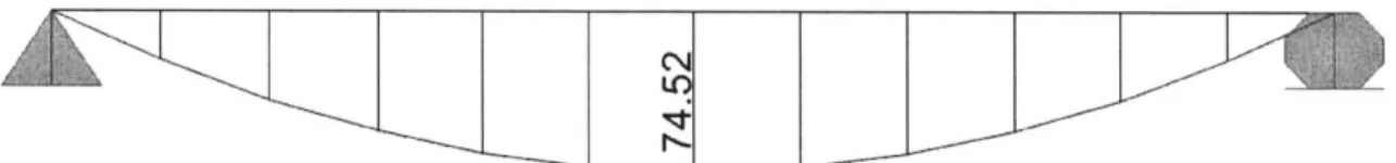
distributed load along the beam, fixity of the connections shifts the moment diagram upward from the simply supported case. This means that the total moment is shared between the positive moment at midspan and the negative moment at the supports, thereby decreasing the design moment. For example, the moment diagram for a simply supported beam with a factored distributed load of 1 k/ft and W I8x35 section is shown in Figure 1. For this simply supported beam, the design moment which the member must be able to resist is 74.5 k-ft., and the midspan deflection is .04329 ft.
Figure 1: Moment Diagram of Simply Supported Beam
In comparison, the moment diagram for a fixed-fixed beam with rigid connections is shown in Figure 2. The fixity at the supports shifts the moment diagram upward, and now the design moment for the beam is only 49.7 k-ft., as compared to 74.52 k-ft. for the simply supported case. The midspan deflection is .008465 ft., as opposed to .04329 ft. for the simply supported case.
Figure 2: Moment Diagram of Fixed-Fixed Beam
By comparing these diagrams, the fixed-fixed beam has a smaller maximum
moment, which is approximately 50 k-ft., compared to the maximum moment of the
simply supported span. Therefore, the fixed-fixed beam has a smaller requirement for the flexural strength of the section. However, this design is not as economical as it could be, because the difference between the negative moment and the positive moment is not minimized. To reach the optimal design moment condition, the moments at the support and at midspan should be equal or close to equal. A semi-rigid beam with a partial fixity factor, which is the relationship between moment and rotation, of 20,000 k-ft./radian gives favorable results, as shown in the moment diagram in Figure 3. In this design, the positive moment at the support and the negative moment at midspan are very similar. Therefore, the semi-rigid beam need only be designed for a flexural strength of 40 k-ft. as opposed to 75 k-ft. for the pinned-pinned case and 50 k-ft. for the fixed-fixed case.
Figure 3: Moment Diagram for Semi-Rigid Beam
However, this may not always be the most desirable case. For example, if deflections are the critical parameter and govern the design, a fixed-fixed beam may be preferable because it will yield the smallest midspan deflections. In particular, semi-rigid
on the scenario, the designer may perform an economic analysis and discover that the potential savings in beam size for a semi-rigid frame do not offset the extra cost of designing semi-rigid connections, and therefore decide to use a braced frame with simpler, cheaper connections. If stiffeners are required in the connection or if the beam must be haunched, then it is unlikely that the savings in beam size will be greater than the cost of these additional connection details. It is usually the case that increasing the depth of a column or beam is cheaper than welding stiffeners to the connection. Nevertheless, the semi-rigid frame is beneficial in some cases in that it presents another option for the design which may be optimal.
2.1 The Moment-Rotation Relationship
The concept of semi-rigidity has been around for a long time, but one of the reasons why this concept is not more often used in practical design of frames is that it is difficult to model. One of the key elements in semi-rigid connections is the moment-rotation curve. This curve is not as important for other types of connections. For
example, in a beam column connection,
Moment
_._....-- moment connections are .-
- -.-. - ~modeled with the
assumption that no relative rotation between the beam and column occurs, whereas for
Rotation pinned connections, it is
Figure 4: Typical Moment-Rotation Curve assumed that the beam is
Courtesy of ESPED [10]
free to rotate from the column. For semi-rigid frames, the response is somewhere between these two cases, and this is why the moment-rotation curve is so crucial.
Moment-rotation curves are not linear. For smaller values of moments the rotation increases more quickly than it does for higher values. This nonlinear behavior is
stress concentrations, local buckling in the vicinity of the connection, and changes in the geometry under the loading. The nonlinear behavior can be exacerbated in certain types of connections, especially bolted connections, where slip can cause a higher rotation than that caused by the moment. [7]
2.1.1 Modeling the Moment-Rotation Curve
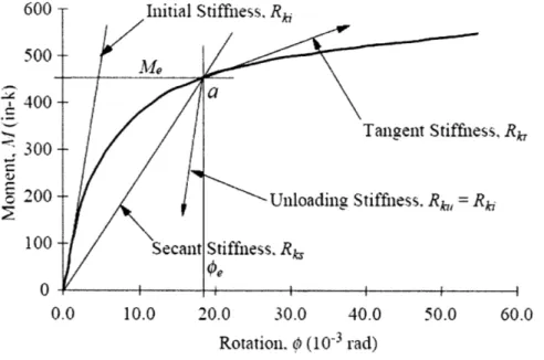
The important parameters of a moment-rotation curve are the initial stiffness, Rki, which is the initial slope of the curve, the secant stiffness, Rks, which is the effective stiffnes of the connection, the tangent stiffness, Rk, which is the instantaneous stiffness, which decreases with increasing moment, and the unloading stiffness, R"u, which is the result of load removals or reversals. Figure 5 shows these stiffness parameters.
600 Initial Stiffness, Rk
500
$ 400
C Tangent Stiffniess,, Rk,
-
300-200 Unloading Stiffness. Rk, = Rki
100 Secant Stiffness. Rk
0.0 10.0 20.0 30.0 40.0 50.0 60.0
Rotation. P (100 rad)
Figure 5: Moment-Rotation Curve
Courtesy of Bjorhovde and Christopher [181
This curve can be obtained by a number of different methods. One method is by experiment. In this case, care must be taken to ensure that the test conditions are an
accurate representation of the design problem. The moment-rotation curve of the actual connection being designed is not known exactly, and the amount of variability in
connection behavior makes this approach uncertain. In order to convert the moment-rotation empirical data into a format that is useful for design, curve-fitting techniques are
three-parameter power model, which models the moment-rotation curve for beam-column connections using double angles to make the connection. The curve is approximated as:
M = RkO where Rki is the initial stiffness of the connection, n is a shape factor,
and Oo is the reference rotation of Mu/Rki. [5]
2.1.2 Classification of Connections by Rigidity
With the concept of semi-rigidity, it is more important to be able to classify connections as "rigid", "semi-rigid", or "flexible". One classification developed by Bjorhovde compares the stiffness of the connection to the stiffness of the connected members. The non-dimensional factor for the connection stiffness is
El
a = where d is the depth of the beam. [2] Using this parameter can help classify Rkid
connections based on their stiffness. The chart which classifies connections based on this factor is shown in L_
__
Figure 6. 0.8 0.6 0.4 0.2 0 0Rigid Sinplilied Ductility Requirement
-- Seii-Rigi
S=10 Fle xible _
0.0 0.3 0.6 0.9 1.2 1.5 1.8 2.1 2.4 2.7 3.0 3.3 3.6
Figure 6: Bjorhovde Classification of Connections Courtesy of Bjorhovde and Christopher 181
Eurocode 3 gives guidelines to approximate the moment-rotation curve, also taking into account that semi-rigid connections exhibit different behavior in braced frames than they do in unbraced frames. The parameters
-M and 0 = - where MP is the full plastic moment capacity of the beam M
and O, = are used to classify connections. Eb
Lb
These parameters define the Moment-rotation curve, which helps engineers to classify different types of connections, as described in Eurocode 3. [10]
For unbraced frames, where sidesway is permitted [10],
m =25*j for M: s 2/3
S25+4 for 2/3 ! Hii 1.0
7
For braced frames, where sidesway is prohibited [10],
M =8*6 for Mis 2/3
200+3 for 2/3 i 1.0 7
The curve for unbraced frames is:
2/3-Simplified bi-linear boundary
Rigid
EC3 boundary Semi-rigid
0,04 0,12
0
Figure 7: Boundary Between Rigid and Semi-Rigid Connections for Unbraced Frames Courtesy of ESDEP [101
The curve for braced frames is:
m
2/3- Rigid
EC3Sboundary Semi-rigid
0 0,04
Simnlifisd hi-linsar hnynrlnrv
0,12
T
Figure 8: Boundary Between Rigid and Semi-Rigid Connections for a Braced Frame Courtesy of ESDEP [101
An alternative to the empirically obtained M- p curve is to use finite element analyses to model the connection and determine the relationship. The benefit of this
technique is that costly materials and laboratory time do not have to be used. Another benefit is that parameters in the model can be changed more easily, and the exact connection details can be modeled. The downsides to this approach are that it is time-consuming and requires a high level of understanding of finite element modeling. This method is suitable for welded connections but is especially difficult for bolts, as bolts have a higher amount of variability and complexity. For instance, with a geometric lack-of-fit, the bolt hole in the plate may be larger than the bolt diameter to an extent that allows more rotation than expected. [17]
2.2 Design of Semi-Rigid Structures
One of the conventional methods of analyzing a beam whose end restraints fall in between the idealized pin and the idealized fixed end is the concept of the "end-fixity
factor". [6] This end-fixity factor, r, is defined as:
a 1
# 3EI
RL
This factor, r, defines the stiffness of the end-connection relative to the attached element. It is the rotation of the end of the beam divided by the combined rotation of the beam and
a
the connection due to a unit end-moment, which is expressed as -. Therefore, for
pinned connections, the end-fixity factor is 0 whereas for fixed connections, the factor is
1. For a semi-rigid connection, then, the end-fixity factor lies somewhere between 0 and
1. This end-fixity factor, r, can be a more useful parameter for characterizing beams than
the rotational stiffness, R, or the connection stiffness ratio, RL/EI, because it has an approximately linear relationship with the moments and deflections.
2.2.1 Moment Distribution Method for Semi-Rigid Design
The end-fixity factor is also useful when applying the moment distribution method to semi-rigid frames. The moment distribution method is a way to solve for the moments in an indeterminate structure by fairly simple hand calculations, using
outlined a method for applying the moment distribution method to semi-rigid frames. [5] This approach is summarized here, with an example to follow:
Expression for the member stiffness factor Kij [5]:
4EI 4EI
KY = S Y and Kji = sji
L L
where the end connection flexibility factors sij are defined as [5]:
3r and s..- 3r
s 4 -"rrj ns
4 -rirj
The distribution factor, DF, which is defined as the stiffness factor of the member divided
by the total stiffness factor for the joint [5]:
K.. DF= "'
The carry-over factor determines the moment to be carried to the far end from the near end, and is defined as the ratio between the far-end moment to the near-end moment. The carry-over factor, C, for semi-rigid frames is defined as [5]:
r. r.
C.. =-!-and C..
=-" 2 " 2
To illustrate the use of this method, it is applied to a simple one-story, two-bay frame, where all connections are defined to be partially fixed, with equivalent spring constants of 20,000 k-ft./radian, as shown in Figure 9, with the joints labeled as shown. The bay widths are 24 ft. and the column heights are 12 ft. A 1 k/ft gravity load was applied to the beams, and the members are all Wi 8x35.
2 PFIXITY 3 PFIXITY
X X X
1 4 6
Using the parameters of the moment distribution method for semi-rigid frames as outlined above, the method was applied to this frame.
For the beams,
1 _
r =.609
1+3 *102,730
20,000 * 24
For the columns, r = 1
K23 = K32 = K35 = K53 K21 =K34 =K65= -For joint 2: DF21 _ K2 3 rbeam 2* EI"a=8620 -rbeam beam 3 rcolumn 4 EIco"umn = 18450 beam column Lcoumn
K21 =.682 1 + K23 DF23 =1-DF, =.318 For joint 3: For joint 5: DF = K32 =.242 K32 +K34 +K35 DF5= .242 by symmetry DF34 = - 2(.242) =.516 DF56 - = -.682 K5 6 +K 53 DF3 =1 -DF6 =.318
For the beams, the fixed end moments (FEM) which serve as the starting point in the moment distribution method were calculated to be
MI = -M 2 = WL
2
2r)
- =33.6 k-ft.12 m 4-r
Joint 1 2 3 4 5 6 Member 12 21 23 32 34 35 43 53 56 65 DF 0 0.682 0.318 0.242 0.516 0.242 0 0.318 0.682 0 FEM (k-_ _ 33.6 -33.6 33.6 -33.6 -22.92 -10.68 +10.69 +22.92 -11.46 -3.25 3.25 11.46 Total Moment (k-ft) .11.46 -22.92 22.92 -36.85 0 36.85 0 -22.92 22.92 11.46
Figure 10: Moment Distribution Method Example for Semi-rigid Frames
These values are similar to the results from the SAP2000 model of the same frame in Figure 11.
2, is~ Z 35
1.28 11.2
Figure 11: SAP2000 Moment Diagram for Semi-Rigid Frame
The accuracy of the moment distribution method to the moment diagram of the
SAP2000 model shows that the moment distribution method can be used for semi-rigid
frames as well as for rigid frames. This is a powerful tool that can be used for simple hand calculations and verification of results.
2.2.2 Frame Design
The overall frame and connections can be designed either from an elastic or a plastic perspective. In general, the calculations for frames and connections need not be
analyzed by the same method. However, a connection which remains in the elastic range until failure should be used in frames that are also designed elastically, unless the
connections are moment connections, and have a higher moment resistance than the connected beams. When elastic theory is used to determine the force distribution in a
connection, it will result in a stiffer connection than the value given by plastic theory. On the other hand, when the connections are designed plastically but the frame is designed elastically, second-order effects should be considered if the ratio between the Euler buckling load and the design load is small. For a global elastic analysis, the spring behavior is considered to be linear, and the connections are modeled as rotational springs. For purposes of simplicity, the elastic design moment is considered to be 2/3 of the ultimate moment, because experimental results show that most beam-column connections behave elastically through 2/3 of their full moment strength.
2.2.3 Stability Design of Semi-Rigid Frames
The stability design of semi-rigid frame is similar to that of rigid frames, where the traditional use of alignment charts for braced and unbraced frames can be modified to
account for the semi-rigid nature of the joints, as proposed by Chen and Lui [6]. For columns connected to beams at both ends with semi-rigid connections with rotational stiffness R, the modified stiffness distribution factor, G, is given as
I G =
alI
Zbib Lb
Where properties with subscript "c" are for the column and properties with subscript "b" are for the beam. The parameter a is a modification factor for the beams which
effectively reduces the moment of inertia, Ib, of the beam. 1
For braced frames, ab = I
+ 2EIb
1+ Rb
For unbraced frames, ac = where R is the rotational stiffness at the ends of the
1±6EI,
b+
Rb
2.2.4 Structural Computer Modeling of Semi-Rigid Buildings
An analysis program, SAP2000, can model structures with semi-rigid
connections. When choosing joint releases, the user can either choose to completely release the moment transfer between connected elements or to specify a partial fixity factor. This is a feature of the newer version of SAP2000 (version 9), which perhaps reflects the trend toward using semi-rigid connections in practical design scenarios. The partial fixity factor is the relationship between the moment and the rotation at the
connection, or the equivalent rotational spring constant. For example, the moment diagram shown above in Figure 3 shows the moment diagram for a beam with partial fixities at both ends of the beam of 20,000 k-ft/radian. In order to check that the results are accurate, it is possible to determine the equation for the moment diagram, integrate it to find the rotation equation, and check that the moment and the rotation at the ends of the beam are related by the specified partial fixity factor. For the beam as shown above in Figure 3, this check was performed. With the loading of 1.0 k/ft plus the dead load of the W I8x35 section, the shear and moment can be expressed as:
V =1.035x -12.42
M V(x)dx 1.035 x2 +12.42x+C, 2
Using the relation that M(x) = EI * dV and M(x) = EI * d,
dx2 dx 1 1-l.035 3 12.422 Ax) =- M(x)dx = x+ x +Clx+C 21 EI EI 6 2 v(x) = J/(x)dx = 1- .035 x4 + 12.42 x3 + § x2 +C2x+C 3] EI 124 6 2
For the W18x35 section used, Ixx = .0246 ft4 and Esteei = 4,176,000 ksf.
Using the boundary conditions that )1(0) = M(0)
20,000
v(0) =v(L) = 0
M -1.035 x2 +12.42x - 34.79 2 1 -1.035 12.42 Ax) = -M(x)dx = x + x2 -34.79x -178.74 EI 6 2 M(O) 34.79 El#(O3.7 = .00174 radians EI * partialfixityfactor .0246 * 29,000 * 12 2 * 20,000
This gives
P(0)=
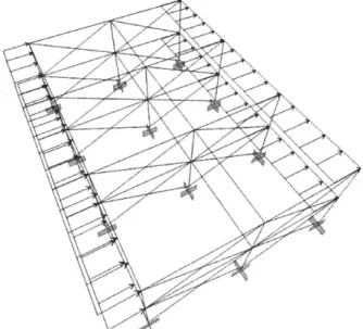
.00174 radians, and M(0) = 34.79 k-ft., which agrees with the SAP2000 results.In addition to studying the properties of the connections, it is important to determine what effect the connections have on the overall behavior of the structure. In order to compare frames with different types of fixity, three SAP2000 models were created. All three models had the same geometry, but the joint fixities as well as bracing members were altered between the models. The geometry of these buildings was a
2-story, 3-bay frame, with a story height of 12 ft. and a bay width of 24 ft. A distributed gravity load of 1.0 kips/ft was
applied to all of the beams, and a
0.25 k/ft distributed wind load >
was applied laterally to the beams in the y-direction, which is the critical direction because the frame is only two bays in the
y-direction as opposed to three bays in the x-direction. The beams and column were designed
to be W2 1 x83 sections. Three Figure 12: Geometry of SAP Model
models were created and analyzed: a rigid-framed model, a semi-rigid model, and a braced frame. The basic geometry of the building is shown in Figure 12.
The braced frame model is braced in the direction of wind loading, as shown in Figure 13. The braces are defined to be the same sections as the other members for
simplicity. All of the
connections, including beam, column, and beam-brace, are idealized pinned
connection, meaning that there is no moment transfer. The model for the semi-rigid frame is the same as that of the rigid frame, except that all connections were assigned a partial fixity factor, which is a new feature of the newer versions of SAP 2000.
Figure 13: SAP Model of Braced Frame
The partial fixity factor for this
frame was chosen to be 200,000 k-ft/radian, which yields a moment of approximately 83
k-ft. It is a reasonable middle point between a rigid connection and a pinned connection,
and produces moments intermediate between the two.
With both gravity loads and lateral loads, a static analysis of the three frames was performed. The maximum values for moment, vertical deflection, and interstory drift were calculated and compared for the three frames.
GRAVITY LOADS ONLY GRAVITY AND LATERAL LOADS
Maximum Maximum Maximum Maximum Maximum
Moment (k- Deflection Moment (k- Deflection Interstory Drift
ft) (ft) ft) (ft) (ft) Rame 70.5 0.00484 103.1 0.00756 0.0642 Semi-Rigid 57.3 0.005963 89.86 0.008596 0.06783 Frame Braced 77.9 0.012621 77.9 0.012621 0.0006633 Frameming Types
These results show the effect that lateral loads have on the system. As predicted
by a traditional understanding of braced frames, bracing elements substantially limit the
maximum interstory drift. The braced frame exhibited an interstory drift approximately
100 times less than the interstory drift for the other frames. Braced frames are generally
thought to be the most efficient structural type for simple frames, but architecturally they are not always feasible. This analysis also illustrates the difference between rigid and semi-rigid frames. With lateral loads, the semi-rigid frame showed a 13% decrease in moment and an approximately 13% increase in the beam deflections. The decision to use one frame over another is based on which aspect of design governs in each particular case. If the flexural strength of the beams governs the design, it might be beneficial to use the semi-rigid frame. The semi-rigid frame has lower design moments, and the savings in beam size for this smaller moment might be significant. On the other hand, if serviceability limit states govern the design, especially interstory drift, it might be more efficient to use the rigid frame, which has lower
deflections.
For the purposes of comparison, the same analysis was run for the same building geometry, but with a total of 12 stories instead of 2 stories. The members, geometries, and loads were kept the same except for the
additional stories added, as shown in Figure 14. Once again, the three frames were a braced frame, a rigid frame, and a semi-rigid frame with partial fixity factors of 200,000 k-ft/radian.
The results from this model were somewhat different from the results for the 2-story model. The result for the rigid frame and the semi-rigid frame became more similar at this
higher building height. The moments for the Figure 14: 12-story SAP model
two-the same as for two-the two-story building. Typically, semi-rigid frames are not used for buildings over a few stories unless some other type of lateral system is added, such as shear walls. In this scenario, it is possible that the combined system of shear wall and semi-rigid, rather than fully rigid, connections would result in savings for the structure.
3. Structural Connections
The previous section describes the modeling of connections and their role in frame design, but it is important to see also how these theoretical models, such as pinned connections and fixed connections, actually exist in the physical structure.
3.1 Pinned and Fixed Connections
Generally, connections between beams or from beams to columns which only connect to the webs of the beams are considered pinned connection. That is, since the shear force is carried in the beam web, only shear is assumed to be
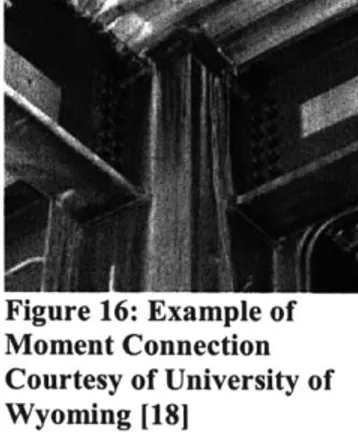
transmitted to the connected element if only the web is connected. One example of this is Figure 15. Using a single angle, as shown above, or a double angle, where the channel
section is on both sides of the web, are the most typical
Figure 15: Example of
methods of making a pinned Pinned Connection connection. On the other hand, if Courtesy of ESDEP 110] the flanges of the beam are connected to the adjacent column or beam, then a moment connection is assumed. One
example, where the beam web is bolted to the column and the Figure 16: Example of beam flanges are welded to the column, can be seen in Figure
Moment Connection
Courtesy of University of 16. These idealizations are usually accurate, although there
Wyoming [181 is usually some amount of moment transfer with pinned
connections which is neglected in design.
In order to achieve the idealized moment connection, the connection should be
both rigid and strength, relative to the connected members. Attaining the full-strength requirement is fairly routine and easily met, but attaining the rigidity
requirement can be more difficult. Rigidity implies that there is minimal flexibility. In order to achieve this, direct load paths through the connection are preferred; it is better to carry loads in axial tension or compression than in bending. [16]
End plate connections:
Figure 19: End Plate
Moment Connection
Figure 18: Haunched Moment Connection
Courtesy of ESDEP [101
Figure 17: Hybrid Moment
Connection
Courtesy of ESDEP [101
The hybrid connection, where the beam web is bolted and the beam flanges are welded to the column is one of the most common in North America. [10]. Although moment
connections are required to resist shear and sometimes axial forces, the moment is usually dominant for
strength. Typically, moment is transferred by axial
compression at the bottom Figure 20: Examples of Stiffened Moment Connections flange and axial tension at the
Courtesy of ESDEP [101 top flange. When the
strength in some region of the connection is insufficient, stiffeners can be added to
strengthen the connection. Some examples of stiffened connections can be seen in Figure 20.
3.2 Semi-Rigid Connections
The physical joints for semi-rigid connections are more complicated to design than simple pinned or moment supports. If pinned joints are those which provide connection to the web of the beam only, and moment connections are those which connect to both the web and flanges of the beam, then semi-rigid connection fall
somewhere between the two. True semi-rigid connections provide a small amount of fixity between the beam flange and the column. However, it is often the case that idealized pinned connections actually have more rotational rigidity than expected; in this case the frame should perhaps have been modeled as a semi-rigid one. For example, joints which involve clip angles either welded or bolted from the column flange to the beam web are usually classified by AISC-ASD as pinned connections, but actually can develop up to 20% of the full fixed-end moment of the beam. Therefore, they provide more rigidity than the structural analysis assumed. Another type of connection, which provides more moment restraint than predicted by AISC-ASD, are the top and seat-angle
connections, where an angle is connected from the column flange to the beam flange. According to AISC specifications, "The seat-angle transfers only vertical reaction and should not give significantly restraining moments on the end of the beam." [7].
However, experiments show that this is not the case; the seat-angle does aid the connection in transferring moment between the beam and the column. The stiffest of semi-rigid connections is considered to be T-stub connections, where T-stubs are bolted to the beam and column at the top and bottom flanges of the beam. [7]
3.3
Welded Joints
There are two main types of welds: groove welds, which are often called butt welds, and fillet welds. Other types of welds including plug, slot, and spot welds are also used. For building structures in general, approximately 80% of the welds are fillet welds,
15% are butt welds, and an additional 5% are some other type of weld. [3] The
assumptions underlying the structural design of welds are that welds are homogeneous and isotropic, residual stresses and stress concentrations in the welds are negligible, and the connected parts are held rigid with negligible deformations. This implies that there is a uniform stress distribution in the weld, which is not actually the case. Although this simplifying assumption is not completely accurate, the material ductility leads to a redistribution of stresses from residual stresses and stress concentrations, resulting in an overall stress reduction. Fillet welds are often preferred to butt welds because they require less equipment, fewer skills of the welder, and less preparation of the elements to
many types of welding processes, many of which are used
2 in the shop. However, field welding usually employs
- ' metal arc welding, because it can be performed in a number of different positions and orientations.
The orientation of the welds relative to the Figure 22: End Fillet Weld connected elements can be important in determining the
Courtesy of ESDEP [101 weld strength. Side fillet welds carry an axial force
parallel to the weld length, as seen in Figure 21. In
contrast, end fillet welds transfer axial loads
perpendicular to the weld length, as in Figure 22. An end fillet weld is generally stronger than a side fillet weld. The main reason for this is that the failure plane for an end fillet weld is larger, due to
the geometry of the connection. Figure 21: Side Fillet Weld
Courtesy of ESDEP [10]
3.4 Bolted Joints
The strength of a bolted connection depends on the resistance of the individual components of the connection. There are two main types of bolts: "ordinary" bolts, which are also called bearing bolts, and pre-tensioned or high-strength bolts, which are used in slip critical conditions. Ordinary bolts are cheaper and preferred when higher
strength bolts are not needed, although in many design scenarios, it is common for engineers to specify high strength bolts.
There are a number of bolt sizes and strengths available. For a bearing bolt that is not pre-tensioned, the bearing strength depends on the shear resistance of the bolt and the bearing resistance of the plates. If the bearing resistance of the plates is less than the shear resistance of the bolts, then the connection has a larger joint rotation capacity. This is more likely to occur when the bolt hole is larger than necessary and when the joint is longer; to protect against this, the bolt hole diameter in the plate is usually limited to the bolt diameter plus one eighth of an inch. [16] In addition to non-pre-tensioned bolts, high strength friction grip (HSFG) bolts are also used. These are used when the stiffness and strength requirements are higher, and especially when the connection conditions are
slip-critical and subject to fatigue. The shear strength of the HSFG bolts depends on the coefficient of friction of the materials and the amount of pretension.
The primary function of bolts is to transfer forces from one plate to another. Bolts usually carry both axial tension or compression and transverse shear. Generally, axial forces through the bolt are preferred, because experimental results show that the shear strength is usually only about 60% of the tensile strength for ordinary bolts. The reason that the shear strength is reduced is due to secondary bending actions caused by lack of symmetry of loading, and by additional rotation of the bolt due to the larger hole diameter than the bolt diameter. Increasing the number of bolts in a joint, which lengthens the joint, can mitigate the reduced shear resistance. However, long joints have undesirable effects on shear resistance too. With long joints, the bolts at the ends of the joint fail first, before the other bolts have developed their full strength. For cases where the joint length is long, the shear strength of the fasteners is reduced by a certain factor to account for this. Especially at low moments, the bolt flexibility causes higher rotations at the connection than the moment would induce. In order to minimize the slippage of the bolt, it is preferable to subject the bolts to axial loads instead of shear whenever possible. It is also beneficial to place the bolts as closely as possible to the beam, provide additional
stiffeners close to the bolts as needed, and maximize the moment arm of the connection, using a haunch if necessary.
In many cases, ordinary or bearing bolts are not permissible, and HSFG bolts are used. The pre-tensioning of the bolts, which must have an initial pre-tension of at least
70% of their ultimate tensile strength, makes the bolt exert a compressive force on the
connected plates. This clamping pressure facilitates load transfer through friction forces.
A connection which uses HSFG bolts is much stiffer than an ordinary bolt, although this
is true only until slip occurs. Slip occurs when the applied loads are higher than what the plates and bolt interfaces can carry in friction, and the plates begin to move relative to
each other. After this occurs, the HSFG bolt behaves as a bearing bolt. Until this point, though, HSFG bolts have very good properties under alternating forces, fatigue loads, and good stiffness properties. They are higher in cost than ordinary bearing bolts.
installation, involves prescribing an amount of torque past the point where the bolt is snug-tight. Typically, bolts are turned one half turn past the snug tight condition, but this may be hard to measure. One of the drawbacks of this method is that it is difficult to measure exactly how much pretension is in the bolt and it is difficult to inspect, although overall it is a reliable method. Another installation method, "calibrated wrench"
installation, is based on the assumption that there is a relationship between torque and pre-tension. Although this is theoretically true, there is a very complex relation
between the two due to the complex geometries, including
-thread pitch and angle, and variance in friction conditions. This complex relationship is accounted for by testing the connections first to determine how much tension is in the
bolts. Then the wrench is calibrated to produce this - -
-amount of tension in the actual connection. Another - -F
solution to control the amount of pre-tension is to use tension control (TC) bolts. In this type of bolt, the end of the threaded part of the bolt has a torque control groove which can determine the amount of torque in the bolt, as seen in Figure 23. Once a pre-determined value of torque is reached, the end of the screw breaks off and the bolt is not tightened beyond this point. This greatly simplifies construction and inspection of bolts, and allows for a greater degree of certainty in the analysis of bolt behavior.
[15]
Other practices and types of bolts can be used in non-typical circumstances. One such example, when
Figure 23: Tension Control B
deformations and rotations are to be minimized, is the use Courtesy of ESDEP 110] of injection bolts. In this type of bolt, the space between
the bolt and the walls of the bolt hole in the plate are filled
with resin. A small hole in the head of the bolt is drilled so that the resin can be injected after the bolt is put in place. This procedure is used to repair riveted joints in
maintenance of historic structures, as well as for situations with high loads, such as railroad bridges.
In addition to strength and deformation concerns, bolts should also be designed for proper corrosion protection. To protect the plates, zinc-coated, or galvanized, bolts may be used. The zinc coating adds friction to the bolt threads and provides protection to weathering corrosion. However, it can increase the possibility of stress corrosion and hydrogen embrittlement. This is a special concern with high strength bolts, which use a higher strength steel. Even a small amount of hydrogen, which is introduced and
absorbed during the galvanizing process or during corrosion reactions, can cause stress-corrosion cracking, a type of failure which occurs under stress-corrosion and high stress.
3.5 Failure of Connections
Some parts of a connection are often designed to yield first, to ensure that if yielding does occur, it happens in a controlled way. This is particularly important in semi-rigid connections, where the connections are more likely to be stressed beyond the yield point and undergo plastic deformations. Sudden yielding, as well as sudden failure, should be avoided in the design. The fasteners, which include welds and bolts in tension, are brittle, and their failure could be catastrophic. Therefore failure of the welds or bolts in tension should be avoided. In semi-rigid connections, all-welded connections, unless they are very standard and certain, are generally avoided. [14]
If the connection is subjected to fluctuating stresses, fatigue may be an issue for
the connection. Fatigue is the mechanism of crack growth and propagation under these fluctuating stresses. Local stress concentrations, due to structural loads and geometric discontinuities, are the main cause of fatigue cracking; however most structural design considers only average stresses at the macroscopic level, ignoring the possible stress concentrations that may form at connections. In particular, welds, which have very small discontinuities in the weld metal, are susceptible to crack initiation and growth. To minimize the chance of fatigue cracking, the joint should be designed to have good fit-up, minimal discontinuities, and a smooth profile. In special circumstances where fatigue stresses are critical, this may involve grinding of the weld surface to achieve a smoother
crack growth. Another practice to reduce the possible of fatigue cracks is the use of peening, or repeating hammering. This causes local yielding of the steel, and is usually
applied at the weld toe where cracks are likely to initiate. [4]
Furthermore, to reduce the risk of sudden failure, if necessary, one or more
components of the connection are purposely designed as a "weak link". This weak link is usually the end plate, which is the plate between the column and the beam as shown in
Figure 24 One way this is achieved is by limiting the maximum plate thickness to 60% of the bolt diameter. [10] Although a thicker end plate could transmit more moment, this would increase the possibility that the bolts might fail before the plate, which would be a brittle and abrupt failure. This is a different approach from strength-based design, in which the end plate thickness is likely to be equal to the bolt diameter. In order to keep the end plate strong, it is preferable to use compact,
closely spaced bolts which are as close to the structural elements as possible. It is usually preferred to have ductile failure. The failure modes which are considered ductile are slippage of bolts in the flanges, yielding of gross area of plates, and yielding of the gross area of the girder. Failure modes which have some ductility
are local buckling of the flange plates, local buckling of Figure 24: Typical
Connection with End Plate
girder flanges. The brittle failure modes, which are Courtesy of ESDEP 1101 undesirable, are block shear of flange splice plates, fracture of flange plate welds, shear fracture of web bolts, and fracture of the net area of the web splice plate or the girder.
3.6 Comparison and Choice of Joints
It is informative to study the different types of connections, but ultimately a choice must be made as to which type of connection to use in a structure. This decision is based on many factors, including the effectiveness of the connection, the ease of assembly, the
availability of resources, and the economic factors. In general, under controlled
conditions, it is easier and cheaper to make a welded connection than a bolted one. This means that for joints which are prefabricated in a shop, welded connections are usually
true, because welding requires better access to the structure, which might not be easily obtained. Welding also requires more skill and licensing of the workers than bolting, as well as temporary bolts and cleats to hold members together. Also, in the field bolts may be preferred because there is less variability than welding, and because bolts are more cheaply and easily inspected. However, both bolts and welding are often used in many different types of structures, depending on the goals and constraints of the connection.
[4]
3.7 Column Trees
One common type of framing often used in seismic zones is the special moment resisting frame. The difference between this type of frame and the ordinary moment resisting frame is based on the amount of ductility in the system. Special moment-resisting frames are designed to have a greater amount of ductility, which acts as a
damping mechanism during earthquakes. Because of this, some codes allow for special moment-resisting frames to be designed for smaller seismic loads than ordinary moment
frames. [1]
The Northridge earthquake in 1994 in particular, as well as the 1995 Kobe earthquake and others have resulted in a
greater concern with field-welded moment frames. Moment frames are often preferred in seismic regions because of their ductility, but the many failures that occurred in these
types of structures during the earthquakes
led to a re-evaluation of field-welded Figure 25: Girder Splice for Moment-moment connections. After these Resisting Column Tree
earthquakes, emphasis was placed on
designing ductile connections for seismic zones, and the minimum rotation to meet this ductility requirement was chosen to be at least .004 radians. [1] One of the methods of fabrication that structural engineers have used more often since the investigations of these earthquakes is connections that are shop-welded and field bolted. This allows for greater
those with snap-off ends, are more easily inspected than welds in the field. One option for shop-welded, field-bolted connections is the column tree, where short sections of the girders are welded to the columns in the shop. The column trees are transported to the site, where they are erected. The middle spans of the girders are then field-bolted to the girder stubs which have been pre-welded to the columns in the shop. These connections are efficient because most of the complicated connection design is done in the shop, so field work is reduced and simplified. A typical field-bolted girder splice is shown in Figure 25.
The first column-tree systems were designed to be rigid frames, where the connections from the
girders to the column trees were stronger than the design strength of the beams. However, it was proposed that making these connections semi-rigid
would increase the seismic L
performance of the Figure 26: Moment Diagram for Rigid Frame with Column Trees structure by increasing
damping, increasing the period of vibration, and
reducing the stiffness in a way that would reduce the effect of seismic loads. [1] Also, the semi-rigid connection from the
Figure 27: Moment Diagram for Semi-Rigid Frame with Column girder to the column
Trees
tree can be used to reduce the moments that are transmitted to the column tree, as in Figure 27. The girder splice where the main span of the girder meets the column tree limits the moments that is
transferred to the column tree, thereby ensuring that failure does not occur at the beam-column connection. By designing the girder splices as bolted connections, the shop-welded, field-bolted benefit can be maintained. Additionally, for seismic design, the bolted connection allows for slip, which can be an important energy-dissipating mechanism during earthquakes. Slip should not be allowed to occur under ordinary service loads, but during extreme loadings such as earthquakes, it can be an important component of the structure's response.
4. Connections for Hollow Structural Sections
Hollow structural sections are in common use in structural engineering. They provide many advantages over traditional rolled sections such as W-shapes, including greater lateral-torsional stability buckling resistance for a given volume of material, and greater aesthetic appeal. The radius of gyration which is defined as r = - is usually
higher for a hollow section than for an open section, such as a W-section about its weak axis. Therefore, hollow sections are useful in instances where buckling about an arbitrary axis is important to control. Both circular hollow sections (CHS) and rectangular hollow sections (RHS) are often used. For members subject primarily to uni-axial bending, rectangular sections with their long side in the plane of bending are most efficient. For bending about two planes, square sections are usually used, and for bending about many planes, circular hollow sections are chosen. Hollow sections also provide better
corrosion protection because there are fewer corners and complex geometric configurations where corrosion is likely to occur.
One of the issues with this type of element is the difficulty in connecting members. With more conventional members, the surfaces are mostly planar and so bolted and welded joints are easier to accomplish. Furthermore, joints connecting hollow members often have several elements framing into one joint location, sometimes at irregular angles, as in a space truss. In contrast, conventional sections generally are more likely to form right angles. These irregular angles, which may not be constant through the structure, further complicate the issue of connections between hollow elements.
An instance in which hollow circular sections (CHS) were used is in the design proposal for the Boston Maritime Museum, which was part of the 1.562 class at MIT for the 2005-2006 year. In the Fort Point Channel area of Boston, this Maritime Museum was proposed as a floating structure with a diagrid exterior. In Section 5.2, the design methods presented are applied to the design of this proposed structure.
One association, the International Committee for the Development and Study of Tubular Construction (CIDECT), seeks to promote knowledge of steel hollow sections.

![Figure 4: Typical Moment-Rotation Curve assumed that the beam is Courtesy of ESPED [10]](https://thumb-eu.123doks.com/thumbv2/123doknet/13945484.451987/11.918.143.728.602.883/figure-typical-moment-rotation-curve-assumed-courtesy-esped.webp)