HAL Id: hal-02419651
https://hal.archives-ouvertes.fr/hal-02419651
Submitted on 19 Dec 2019HAL is a multi-disciplinary open access
archive for the deposit and dissemination of sci-entific research documents, whether they are pub-lished or not. The documents may come from teaching and research institutions in France or abroad, or from public or private research centers.
L’archive ouverte pluridisciplinaire HAL, est destinée au dépôt et à la diffusion de documents scientifiques de niveau recherche, publiés ou non, émanant des établissements d’enseignement et de recherche français ou étrangers, des laboratoires publics ou privés.
C. Venard, C. Coquelet, A. Conti, D. Gentet, P. Lamagnere, R. Lavastre, P.
Gauthe, B. Bernardin, T. Beck, D. Lorenzo, et al.
To cite this version:
C. Venard, C. Coquelet, A. Conti, D. Gentet, P. Lamagnere, et al.. The astrid core at the end of the conceptual design phase. FR17, Jun 2017, Yekaterinburg, Russia. �hal-02419651�
The ASTRID core at the end of the conceptual design phase
C. Venard
1, C. Coquelet-Pascal
1, A. Conti
1, D. Gentet
1, P. Lamagnère
1, R. Lavastre
1, P.
Gauthé
1, B.Bernardin
1, T. Beck
1, D. Lorenzo
1, Anne-Claire Scholer
2, Benoit Perrin
2, Denis
Verrier
21
CEA, 13108 Saint-Paul lez Durance, France
2
AREVA-NP, 10 rue J.Récamier, 69456 Lyon, France
E-mail contact of main author: christophe.venard@cea.fr
Abstract.
Within the framework of the French ASTRID project, core design studies are being conducted by the CEA with support from AREVA and EDF. The design studies include the GEN IV reactor objectives, particularly in terms of improving safety.Options selection was performed at the conclusion of the pre-conceptual design phase. The CFV core was confirmed as the reference core for the ASTRID project. The design routes of the core have be reoriented for the conceptual design phase of the ASTRID project :
- Limitation of the core diameter,
- Innovative options of control and shutdown architecture : control and safety absorber rods used to manage the core reactivity during the cycle,
- Introduction of complementary safety device for prevention and mitigation of severe accidents, - Choice of S/A internal storage instead of external storage,
- Neutron shielding on the Inner vessel components.
At the end of the ASTRID conceptual design phase (2015), a new evolution of the CFV core (CFV V4) which integrated these above options was designed. This paper will describe the CFV V4 focusing core performances, behavior during unprotected transients.
Key Words: ASTRID, Conceptual Design, CFV core.
1. Introduction
The pre-conceptual design phase for the ASTRID [1], [2] prototype (Advance Sodium Technological Reactor for Industrial Demonstration) ended in 2012. Two kinds of cores have been studied :
- the SFR V2b concept [3] at 1500 MW, an homogenous core with a low reactivity swing. - the CFV concept [4], an heterogeneous core based on the introduction of a sodium plenum
zone, an absorbing zone in upper neutron shielding and an internal fertile in a specific core geometry that leads to a low total sodium void effect.
The CFV is the reference during this design phase. Two versions of the CFV core were studied. The version V1 [5] showed a promising safety improvement compared to SFR V2b. The options chosen (decrease of nominal fuel temperature, linear power rate and reactivity swing) for the CFV V2 [6] further improves the natural behavior during unprotected transients.
Option selection and cost savings processes were performed at the conclusion of the pre-conceptual design phase. They confirmed the choice of the CFV core as the reference core for the ASTRID project. The design routes of the core have been reoriented for the conceptual design phase of the ASTRID project :
- limitation of the core diameter less than 3,4 m,
- innovative options of control and shutdown architecture : control and safety absorber rods used to manage the core reactivity during the cycle,
- introduction of complementary safety devices for severe accidents prevention and mitigation, - choice of S/A internal storage (inside the reactor vessel) instead of external storage,
- neutron shielding on the vessel inner components.
New versions of the CFV core which integrated these above options were designed during the conceptual design phase. This paper describes the last one, CFV V4, focusing core performances, behavior during unprotected transients.
2. Safety goals and performance targets
The safety and performance goals assigned to the CFV core by the ASTRID project can be synthesized by :
- a natural behavior as favorable as possible which could be supplemented by some Safety Complementary Devices (DSC-P) during Unprotected Loss Of Flow (ULOF) transients to avoid sodium boiling with sufficient margins or an unprotected Control Rod Withdrawal (CRW) with a criterion of "0% molten fuel",
- a negative sodium void effect,
- and a search for the best performance in terms of fuel burn-up and S/A residence time and breeding gain.
These objectives translate into decoupling safety criteria or safety goals for the core design, the most structuring ones being listed below :
- during the ULOF
o the sodium temperature must be lower than the saturation temperature of sodium,
o the temperature of the fuel S/A clad and the wrapper tube have to be respectively lower than 825 °C and 800 °C,
o the asymptotic coolant temperature has to be lower than 700 °C. - respect of the reactivity control requirements,
- maximal nominal temperature of the fuel S/A clad (NCT) lower than 620 °C in the core,
-
clad damage lower than 110 dpa NRT(Fe).The main performance targets are given in TABLE I.
TABLE I : PERFORMANCES TARGETS OF THE CFV CORE
Thermal power
1500 MWth
Inlet/outlet coolant Temp.
400 °C/ 550 °C
Average fuel burn up
> 80 GWd/t
HMBreeding gain
0
0.02
Fuel residence time
1500 efpd
Cycle length
from 360 to 490 efpd
Core pressure drop
< 3.5 bar
3. Layout of the CFV core (CFV V4)
3.1 Fuel S/As
The number of the fuel pins and S/A is optimized according several criteria : fuel cladding mechanical interaction by power increase, control rod withdrawal, core pressure drop. The number of the core Pu enrichment zones and the enrichment ratio between zones is determined with respect to the flattening and the stability of the core power distribution during the irradiation. This CFV core is composed of 288 fuel S/As : 180 in the inner core and 108 in the outer core. The main geometrical characteristics are gathered in [7].
3.2 Architecture of Absorbers S/As and Shutdown system
The absorber device of the CFV core is composed of 3 kinds of S/A : control and shutdown S/As (RBC), diverse control and shutdown S/As (RBD) and safety complementary S/As (DCS-P). All RBC and RBD devices are involved in the control and the shutdown of the reactor as opposed to the pre-conceptual phase where only the RBC S/A were used. RBD S/As can be inserted even in a deformed core.
The layout of the absorber S/As is optimized to minimize their number. This optimization takes into account the following parameters for the whole reactor’s life :
- the variability of the fuel isotopic vector
- reactivity provisions for the needs of experimental and industrial demonstration programs - the dimensional constraints of the different systems that cross the above core structure, - the reactivity control requirements,
- the management of the core power distributions, - non fuel melting during a CRW,
- and a residence time equal to those of the fuel S/As.
This optimization has led to an absorber system with 9 RBC, 9 RBD and 3 RBH.
3.3 Neutron Shielding of the Core [8]
The core neutron shielding is designed to limit the irradiation damage on the internal components of the vessel and the sodium activation of the secondary heat transfer circuit. The sodium activity in the steam generator area must be lower than 20 Bq/cm3. The upper neutron shielding is integrated at the top of fuel S/A [7]. It also contributes to the sodium void effect of the CFV core [4].
The design of the core neutron shielding is optimized in respect with the ratio efficiency/cost on the basis of selected material. The shielding materials were chosen according to feasibility criteria and experience feedback. The upper neutron shielding is provided by a boron carbide sleeve. The boron carbides is 90% enriched in 10B in the lower part and natural (19.78% of 10B) in the upper part. The
radial neutron protection of the core consists of 11 rows of S/A composed of a sandwich of MgO reflector S/A and natural boron carbide shielding S/As. The secondary sodium activity is about 8 Bq/cm3 including the borated steel shielding of the intermediate heat exchanger [8].
3.4 Internal Storage and Debugging Positions
The assessment of the internal storage capacity needs to plan the core management during the
whole life of the reactor taking into account :
- the phase from start-up core to equilibrium core,
- the phase of increase in S/As performances (from 60 dpa to 150 dpa or residence time from 720 efpd to 2000 efpd),
- the different transitions phases in core management.
Core management is optimized in order to minimize the under-burnup of the fuel S/As and/or the internal storage capacity. Among all studied scenarii of core management, the most interesting one considers an internal storage capacity of 3 batches (216 positions) during the phase from start-up core to equilibrium core (managed with 4 batches of fuel S/As) and 2 batches (144 positions) during the core equilibrium phase. Morever 28 debugging positions are required with a hypothesis of 7 clad failures per cycle.
The implementation of the intental storage and debugging positions has to avoid any significant neutron coupling with the core : the fission power of the fuel S/A in internal storage position must be much smaller than its decay power. Moreover it should remain subcritical, with margin, because no reactivity control devices are provided unlike in the core. The internal storage should not lead to significant degradation of the neutron core shielding or of the mechanical behavior of the core.
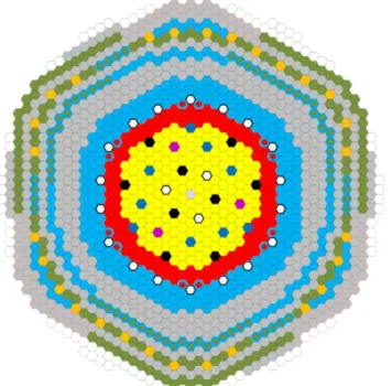
3.5 Core Layout
The configuration of the core CFV V4 incorporates the conclusions and recommendations of the various reviews that occurred at the end of the pre-conceptual design phase and during the conceptual phase :
- Innovative architecture of the control and shutdown rods. Compared to previous architectures (EFR or SPX), this solution saves three absorbers S/As for the same efficiency.
- Complementary safety device for prevention (DCS-P) and mitigation (DCS-M) of severe accidents have been implemented.
- Lateral neutron shielding provided by 11 S/As rows with an alternation of MgO S/As and B4C
S/As.
- B4C upper neutron shielding whose lower part is enriched to 90% in 10B to provide a negative
sodium void effect.
- Introduction of an internal storage.
Natural behavior improvement of the CFV V2 during ULOF was not significant enough to offset the radial size increase (1 more fuel S/As row than CFV V1). It was therefore decided to go back to the CFV V1 border.
The main characteristics of the core are gathered in the TABLE II and compared with the former version of the core CFV V2 (pre-conceptual phase core).
TABLE II : MAIN CHARACTERISTICS OF THE CFV CORE CFV V2 CFV V4
nb of fuel S/As 355 288
nb of pins per S/As 271 217 fuel pin diameter (mm) 8.57 9.7
S/A pitch (cm) 17.5 17.17
inner/outer fissile height (cm) 60/90 60/90 inner/lower fertile height (cm) 20/30 20/30 inner/outer Na plenum (cm) 40/30 40/30
The central position occupied by a dummy S/A in the nominal configuration, will be able to accommodate an absorber S/A (RBC or RBD). During reactor life the core outer contour will be able to evolve : 12 peripheral positions of the core in reflector zone will be able to be loaded with fuel S/As.
During reactor life the capacity needs of the internal storage range from 0 to 216 positions (3 batches of fuel S/As). 72 positions are necessary for the core during equilibrium cycles. Free positions on the diagrid can be used as "buffers". They can be occupied by reflectors S/As in the internal storage configuration with 216 positions. The CFV V4 core layout is shown in FIG. 1.
4. Performances
4.1 Neutron Performances
Neutron core calculations were performed with the CEA's reference code system ERANOS ([9], [10]). The core is managed with 4 batches of fuel S/As. The fuel residence time is 1440 efpd and the equilibrium cycle length is 360 efpd. The main neutron performances are presented in TABLE III.
TABLE III : CFV V4 NEUTRON PERFORMANCES
PuO2 enrichment (vol. %) Inner core / Outer core 22.95 / 19.95
Pu mass (t) 4.8
Reactivity loss per day (pcm/efpd) 3.7
Average breeding gain -0.01
Average power density (W/cm3) 225
Maximum S/As power (MW) 6.1
Maximum linear rating (W/cm) 463
Average burn-up (GWd/tHM) 80
βeff (pcm) 368
EOEC sodium void worth ($) -0.3
The CFV V4 complies with the performance requirements of the ASTRID specifications in terms of fuel residence time, fuel cycle length, average burn-up and breeding gain.
4.2 Core Hydraulic Characteristics
The CFV V4 core hydraulic studies were carried out with the CEA's code TRIO_U-MC2. The maximal nominal clad temperature (NCT) should be lower than 620 °C and the S/As outlet temperature discrepancies between 2 neighboring S/As is limited to 50 °C. The core hydraulic optimization leads to a distribution over 5 cooling groups for the fuel S/As (TABLE IV) to get a flat temperature distribution. The core pressure drop is about 2.7 bar. The maximal NCT and outlet temperature of fuel S/As are respectively 618 °C and 574 °C. The impact of the internal storage and the debugging zone is about +6 °C on the fissile outlet temperature.
TABLE IV : MASS FLOW RATES OF S/AS S/As number Flow per S/A
(kg/s)
Flow per group (kg/s)
fuel S/As 288 7208
group 1 (inner core) 120 26.1 3132
group 2 (inner core) 60 23.6 1416
Inner core 180 4548
group 3 (outer core) 24 26.7 641
group 4 (outer core) 51 25.0 1275
group 5 (outer core) 33 22.5 743
Outer core 108 2660
4.3 Mechanical Equilibrium of the Core
The analysis of static mechanical of the CFV core has aimed to
- optimize pad design in relation to the dynamic behavior of the core
- verify the functional criteria including uncertainties, on the main operating parameters - verify the compactness of the core at the nominal-power state.
TABLE V : MAIN OPERATING PARAMETERS RESULTING FROMMECHANICAL EQUILIBRIUM OF THE CORE
Criterion Compactness
(% pad contact in Outer core) 78% > 70% Bowing of absorber S/A head 5.5 mm < 10 mm Permanent Bowing at S/A head 7.9 mm < 16 mm Bowing in handling 4.4 mm < 10 mm Handling force 12.9 kN < 18 kN
5. Core behavior during transients overpower
5.1 Control Rod Withdrawal
Since the ASTRID pre-conceptual design phase, the core evolutions (Absorber system architecture, fuel pellet design [7]) have led to improve the core behavior during a CRW (reduction of reactivity insertion, and increase of the melting linear power rate). The unprotected CRW do not result in the melting of the fuel. The minimal margin on the Plin is about 50 W/cm.
5.2 Seismic behavior of the core
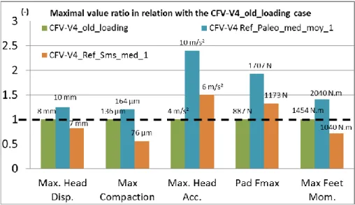
Two types of seism are considered: paleoseism and the SMS (safety majored earthquake). Compare to the pre-conceptual design phase, seismic loadings have been updated and are more penalizing (increase by a maximum factor of 5).
The studies results are showed in FIG. 2 in the case of the horizontal acceleration. Paleoseism is the most penalizing and significantly increases the head accelerations (factor 2.4), pads forces (+ 90%) and spike moments (+ 40%), and the head displacements (+ 25%). The core compaction increases but remains relatively small. The reactivity insertion should be much less than 1$.
FIG. 2 : Maximal values of the core characteristic parameters during seismic simulation
6. Core behavior during unprotected loss of cooling transients
To improve the natural behavior of the core during unprotected loss of cooling transients, passive safety complementary devices are added (RBH, hydraulic trigger DCS on flow decrease, and RBD with Curie point electromagnet).
Among all the transients sequence simulated with the CATHARE code [11], two are presented here-after : ULOF/PP (unprotected loss of flow without reactor scram resulting in the coast down of the primary coolant pumps) and ULOHS (unprotected loss of heat sinks : the secondary pumps are tripped and the steam generators dry out without reactor scram).
6.1 Unprotected Loss of Flow ULOF/PP
This transient represents a tripping of primary pumps leading to a shutdown with a half-flow after 10 s. RBH device falls when the primary pumps flow is below threshold flow of 45% QN. About -2 $ are injected which will be compensated partially and quickly with the Doppler Effect due to the fuel cooling. The neutron power of the core quickly falls to 300 MW and decreases more slowly after the RBH shutdown to reach 65 MW.
The Na outlet temperature peak all over the core pipes (groups of fuel S/As) is 725 °C, 17 s. after the transient beginning which corresponds to 775 °C for the hottest S/A. The mean outlet temperature then stabilize to a value of 470 °C after 1000 s. while the sodium flow through the core stabilize at about 370 kg/s by natural convection.
FIG. 3 : Na temperature during ULOF/PP
6.2 Unprotected Loss of Heat Sink ULOHS
The graphs in FIG. 4 show the temperature increases at the core inlet and outlet when the secondary coolant pumps are tripped without reactor scram, the steam generators are dried and the primary flow is maintained until the temperature of the RBD electromagnets reaches 650 °C after 500 s from the beginning of the transient. The RBD device falls down and an anti-reactivity of about 7 $ is inserted in the core. Thus, the RBD S/As avoid the temperature of the cold collector increase beyond the seizure temperature of the primary pumps and decrease the neutron power to decay heat level. The core inlet and outlet temperatures tend toward a relatively low smothering temperature ( 620 °C).
FIG. 4 : Temperature during an ULOHS
7. Conclusion
The CFV V4 design integrates the options selection performed at the end of the conceptual design phase : control and shutdown "RID" architecture, introduction of complementary safety devices for prevention and mitigation of severe accidents, choice of a S/As internal storage. The neutron performances and the static mechanical analyses of the CFV V4 core comply with the ASTRID project requirements.
The new absorber rods architecture and the new design of the fuel pellets lead to a better behavior during CRW transient. The studies of the core CFV V4 behavior highlight the efficiency of the DCS-P (RBH and RBD with Curie point electromagnet) during the unprotected loss of cooling transients. The CFV core studies go on during basic design phase [12] taking into account the evolution of ASTRID project and the new available experimental results.
8. Acknowledgments
The authors wish to thank all the teams involved in the core design at CEA, AREVA and EDF.
9. Nomenclature
BEOC : Beginning Of Equilibrium Cycle
CFV : "Coeur à Faible Vidange" Low Sodium void Core CRW : Control Rod Withdrawal
DCS : Safety complementary device
DCS-P : Prevention Safety complementary device RBH : hydraulic trigger DCS on flow decrease DCS-M : Mitigation Safety complementary device DCS-M-TT : Crossing pipe DCS-M
EFPD : Equivalent Full Power Day EOEC : End Of Equilibrium Cycle IS : Internal Storage
NCT : Nominal clad temperature Plin : Linear power rating QN : Nominal flow rate
RBC : Control and shutdown device
RBD : Diverse control and shutdown device S/A : Subassembly
ULOF: Unprotected Loss of Flow by Primary pump tripping ULOHS : Unprotected Loss of Heat Sink
10. References
[1] P. LE COZ, et al., “Sodium-Cooled Fast Reactors: the ASTRID Plant Project” – Proceedings of ICAPP 2011, Nice, France, May 2-5, 2011.
[2] B. FONTAINE, et al., “Sodium-Cooled Fast Reactors: the ASTRID Plant Project” – Paper 432757, Proceedings of GLOBAL 2011, Makuhari, Japan, Dec. 11-16-5, 2011.
[3] P. SCIORA et al., "A break even oxide fuel core for an innovative French sodium-cooled fast reactor : neutronic studies results”, Global, Paris, France, Paper 9528 (2009).
[4] P. SCIORA, et al., “Low void effect core design applied on 2400 MWth SFR reactor” – Proceedings of ICAPP 2011, Nice, France, May 2-5, 2011.
[5] F. VARAINE et al., “Pre-conceptual design study of ASTRID core” – Paper 432757, Proceedings of ICAPP 2012, Chicago, USA, June 24-28, 2012.
[6] MS. CHENAUD et al., "Status of the astrid core at the end of the pre-conceptual design phase 1", Nuclear Engineering and Technology , Volume 45, n° 6, November 2013.
[7] T. BECK, et al., "Conceptual Design of Fuel and Radial Shielding Sub-Assemblies for ASTRID" - Paper IAEA-CN-245-128, FR17, Yekaterinburg, 2017
[8] N. CHAPOUTIER et al., "ASTRID core shielding – Design studies and benchmark analysis" – Paper 15305, ICAPP 2015, Nice, France, May 3-6, 2015
[9] G. RIMPAULT et al., "The ERANOS code and data system for fast reactor neutronic analyses" – Proc. Int. Conf. on Physics of reactors, Seoul, Korea, 2002.
[10] R. LE TELLIER et al., "High-order discrete ordinate transport in hexagonal geometry : a new capability in ERANOS" – 21st Int. Conf. on Transport Theory (ICTT-21), Torino, Italy, 2009. [11] GEFFRAYE et al., "CATHARE 2 V2.5_2: A single version for various applications", Nuclear
Engineering and Design, Volume 241, Issue 11, November 2011, Pages 4456-4463
[12] J.G. GROUILLER, et al, " Plutonium recycling capabilities of ASTRID reactor" – Paper IAEA-CN-245-348, FR17, Yekaterinburg, 2017