HAL Id: hal-01844598
https://hal.archives-ouvertes.fr/hal-01844598
Submitted on 19 Jul 2018HAL is a multi-disciplinary open access archive for the deposit and dissemination of sci-entific research documents, whether they are pub-lished or not. The documents may come from teaching and research institutions in France or abroad, or from public or private research centers.
L’archive ouverte pluridisciplinaire HAL, est destinée au dépôt et à la diffusion de documents scientifiques de niveau recherche, publiés ou non, émanant des établissements d’enseignement et de recherche français ou étrangers, des laboratoires publics ou privés.
Synthesis of carbon coating and carbon matrix for C/C
composites based on a hydrocarbon in its supercritical
state
Laurence Maillé, Y. Le Petitcorps, A. Guette, G. Vignoles, J. Roger
To cite this version:
Laurence Maillé, Y. Le Petitcorps, A. Guette, G. Vignoles, J. Roger. Synthesis of carbon coating and carbon matrix for C/C composites based on a hydrocarbon in its supercritical state. Journal of Supercritical Fluids, Elsevier, 2017, 127, pp.41 - 47. �10.1016/j.supflu.2017.03.015�. �hal-01844598�
*
Corresponding author: Maillé Laurence, LCTS, 3 allée de la Boetie – 33600 Pessac - France (permanent address)
maille@lcts.u-bordeaux.fr tel.:33-556844712
Synthesis of carbon coating and carbon matrix for C/C composites based on
a hydrocarbon in its supercritical state
L. Maillé*, Y. Le Petitcorps, A. Guette, G. Vignoles, J. Roger University of Bordeaux, LCTS, UMR 5801, F-33600, Pessac
Keywords: supercritical fluid, Chemical Vapor Deposition (CVD), Chemical Vapor
Infiltration (CVI), C/C composites
Abstract
This study addresses a new process for the fabrication of a C/C composite for aeronautic and aerospace industries. The infiltration of a carbon fibrous preform by means of a hydrocarbon in the supercritical fluid state is carried out at high temperature in order to get a carbon matrix. The selected hydrocarbon is methane. The microstructure of the pyrocarbon coating is characterized by optical microscopy, Transmission Electron Microscopy and Raman Micro-Spectroscopy. The experimental parameters (temperature, hydrocarbon pressure, residence time) are tuned in order to improve the carbon matrix yield. The feasibility of a dense composite from a precursor in its supercritical state, reducing the infiltration duration as compared to Chemical Vapor Infiltration (CVI), is demonstrated.
Introduction
Ceramic Matrix Composites are developed for aeronautic and spatial applications [1] for their refractoriness and their low density. Starting from a woven carbon fiber preform, C/C composites are usually obtained by a long Chemical Vapor Infiltration (CVI) step, using as precursors gaseous hydrocarbons such as propane [1]. However, CVI is a rather time-consuming process, which is a huge drawback. As a result, the manufacturing cost of these composites is very high. In order to reduce the cost, other processes can also be used to prepare the matrix, such as liquid phase routes with mineral charges [2-8].
In this paper, we explore a new and original densification process in order to prepare a Carbon/Carbon (C/C) composite: the Chemical Supercritical Fluid Infiltration. A supercritical fluid is a substance taken at a temperature and pressure above its thermodynamic critical point. Its properties are simultaneously those of gases and liquids [9].
2
Supercritical fluids are commonly used as solvents in industrial processes with applications in various sectors such as food, cosmetics, or pharmaceuticals. These processes include: i) extraction / fractionation [10-12]; ii) purification / recycling [13-15]; and iii) synthesis of materials
[16-17]
. Supercritical fluids have the unique ability to diffuse through porous solids like a gas, and to dissolve species like a solvent. This combination of the solvent ability and the high diffusivity should enable a rapid infiltration and a good densification of the porous preform. Application to pyrocarbon infiltration results in a rapid densification of fiber preforms [18-21]. Preliminary results revealing the potential of this technique are reported and discussed in the next sections of this article, considering either deposition on a dense substrate or infiltration in a porous substrate.
1. Preliminary study
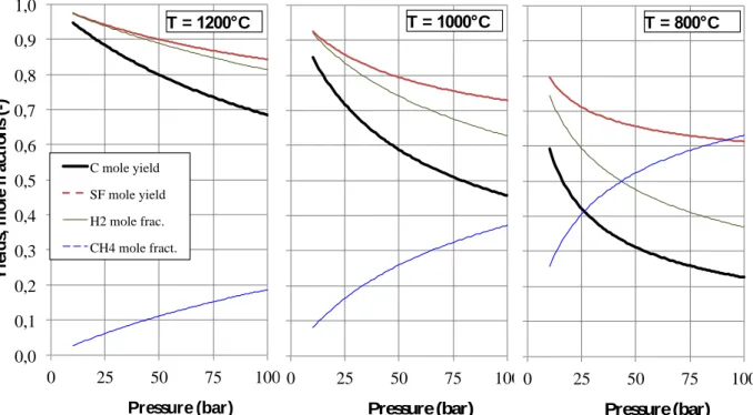
Before performing experiments, the potential gains of working in supercritical conditions instead of classical CVI conditions are investigated with a thermochemical study. Also, a first guess of the influence of the operating parameters is expected from these computations. The stability of all the chemical components in the experimental conditions (temperature and pressure), starting from pure methane, was assessed by a calculation of the thermochemical equilibrium of carbon and several hydrocarbons using the Thermocalc 3.0 software [22-24]. The relative equilibrium amounts of the different phases (Supercritical Fluid SF and solid carbon) are analyzed, in order to quantify thermodynamically the carbon deposition yield (i.e. the number of carbon moles compared to the initial number of methane moles), the SF yield (i.e. the number of SF moles compared to twice the number of methane moles). Fig. 1 represents the evolution of the equilibrium yield of SF and solid carbon with pressure (P∈ [10; 100] bar), together with the mole fractions of H2 and CH4 in the final SF, for temperatures ranging
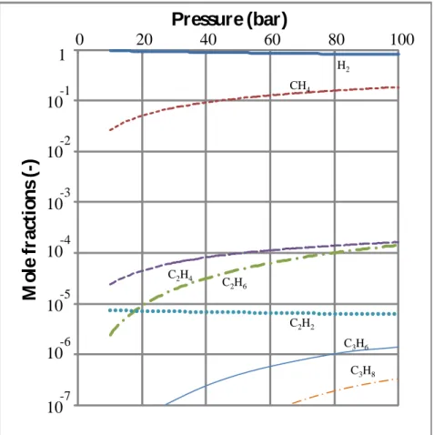
from 800 to 1200°C. The influence of the pressure on the fluid composition at 1200°C is shown Figure 2, in which the thermodynamic stability of CH4 is seen to increase with
pressure. The mole fractions of CH4 and H2 sum up to close to unity, since the equilibrium
partial pressures of all other hydrocarbons are negligible (below 2.10-4 in all cases). The system behaves as if there were only a single equilibrated reaction:
CH4 (sf) C (s) + H2 (sf) (1)
The thermodynamic calculations results of Fig. 1 show a decreasing stability of the solid phase and a decreasing yield of SF with increasing pressure. This is in accordance with Le
3
Châtelier’s principle [25]
. On the other hand, since reaction (1) is endothermic, the yield increases with temperature. Therefore, high temperatures and low pressures would be the most adequate conditions on a thermodynamic point of view. So it seems better to work at a pressure close to the critical pressure (46 bar). However, the actual choice of appropriate temperature will result from a trade-off between the thermodynamic predictions on the one hand and on kinetics considerations on the other hand. Experimentally, solid carbon formation appears only above 850°C at an initial pressure of 50 bar.
Figure 1.Computed equilibrium yields of solid carbon (C) and supercritical fluid (SF) and methane (CH4) and dihydrogen (H2) mole fractions at selected temperatures versus pressure.
0,0 0,1 0,2 0,3 0,4 0,5 0,6 0,7 0,8 0,9 1,0 0 25 50 75 100 Y ie ld s, m o le f ra ct io n s (-) Pressure (bar) C mole yield SF mole yield H2 mole frac. CH4 mole fract. 0,0 0,1 0,2 0,3 0,4 0,5 0,6 0,7 0,8 0,9 1,0 0 25 50 75 100 Y ie ld s, m o le f ra ct io n s (-) Pressure (bar) 0,0 0,1 0,2 0,3 0,4 0,5 0,6 0,7 0,8 0,9 1,0 0 25 50 75 100 Y ie ld s, m o le f ra ct io n s (-) Pressure (bar) T = 1000°C T = 800°C T = 1200°C
4
Figure 2. Computed influence of pressure on the composition of the supercritical fluid at
1200°C.
2. Materials and experimental procedures
Two types of materials were used: (i) graphite pipes (6 cm length, 0.6 cm diameter)were used as a substrate for the kinetic studies of the deposition, and (ii) 3D porous carbon fibrous preforms (2 cm length, 1.5 cm diameter) for infiltration study. The initial open porosity of the preforms was around 77%.
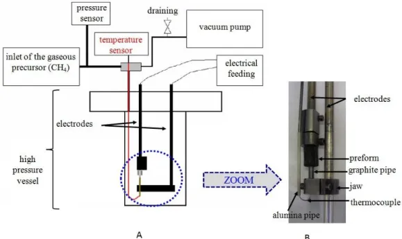
A sealed cold wall reactor made of Inconel alloy was used at high pressure, in batch mode. It is schematically represented in Figure 3. The graphite pipe was heated by Joule effect. The temperature was measured by a thermocouple whose wiring was protected by an alumina tube and whose extremity was inserted in a graphite tube.
1 0 20 40 60 80 100
M
o
le
f
ra
ct
io
n
s
(-)
Pressure (bar)
H2 CH4 C2H6 C2H4 C2H2 C3H8 10-1 10-2 10-3 10-4 10-5 10-6 10-7 C3H65
Figure 3. Schematic representation of the cold wall reactor (A)
and photograph of the interior of the reactor (B).
For kinetic studies, thin films were deposited using methane (CH4) as the carbon precursor (Tc
=-82.6°C and Pc = 46 bar) on the graphite pipes during 10 minutes with an initial pressure of
50 bar at 950°C.
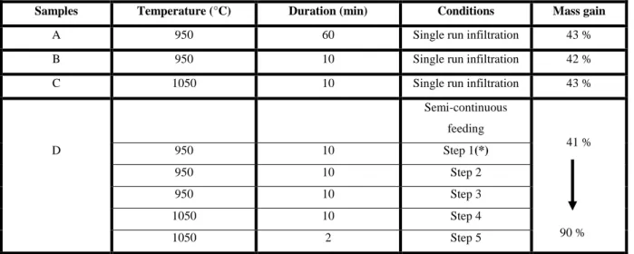
For infiltration studies, 3D porous carbon fibrous preforms were used, with the same carbon precursor. The durations and temperatures selected for the single-step (batch) infiltration varied between 10 and 60 minutes and 950°C and 1050°C respectively (Table 1, sample A-B and C), with an initial pressure of 50 bar.
Another experiment with five successive runs of infiltration (semi-continuous feeding), described in Table 1 (sample D), was carried out to improve the matrix densification, with an initial pressure of 50 bar.
Thin films and composites were observed with a Reichert-Jung MeF3 apparatus on polished surfaces by reflection optical microscopy. Observations under natural light were made to estimate the thickness of thin film and to detect a possible gradient of densification from the internal to the external part of composites. The degree of anisotropy of pyrocarbons was determined under crossed polarizers by the classical extinction angle method.
6
Table 1. Infiltration conditions of the 3 D carbon preforms.
(*) For each step, the vessel is evacuated and then refilled with the CH4 precursor at a constant pressure of 50 bar.
Transmission electron microscopy (TEM) analyses were carried out with a Philips CM30ST TEM (LaB6 operated at 300kV) with a point resolution of 0.2 nm and an information limit of
0.12 nm. Selected area electron diffraction patterns and (002) dark field mode images were acquired on the sample. A JEOL Ion Slicer (EM-09100IS) device was used to prepare the sample.
Raman microspectrometry analyses were performed on the same polished cross-sections as with optical microscopy, with a Labram HR spectrometer (HORIBA Jobin Yvon) using a 632 nm emission line and an analyzer for polarized light. The spectra were interpreted as recommended by Vallerot et al. [26] and compared to known families of pyrocarbons [27].
3. Results and discussion
3.1 Kinetic study of pyrocarbon coating on a graphite pipe
With a sufficient residence time, it is possible to obtain an important thickness of pyrocarbon: 33 µm for 10 min. It confirms the relevance of using a supercritical fluid. By comparison, several hours are necessary to reach the same thickness with the CVI-process at a similar temperature (~ multiplied by 1000) [28].
Samples Temperature (°C) Duration (min) Conditions Mass gain
A 950 60 Single run infiltration 43 %
B 950 10 Single run infiltration 42 %
C 1050 10 Single run infiltration 43 %
Semi-continuous feeding 41 % D 950 10 Step 1(*) 950 10 Step 2 950 10 Step 3 1050 10 Step 4 1050 2 Step 5 90 %
7
The thickness of the pyrocarbon coating varies significantly along the pipe due to the presence of a temperature gradient (Fig. 4). As in classical CVI, the temperature is a very influential parameter.
Figure 4. View of graphite pipe inside the reactor (A) and influence of the temperature
gradient of the graphite pipe on the thickness of the pyrocarbon deposit along the graphite pipe after 10 minutes of deposition (B).
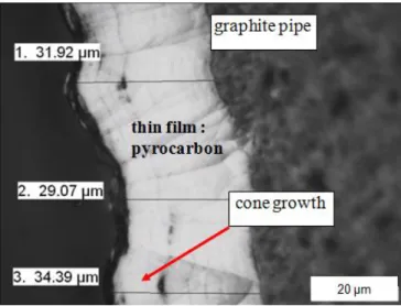
The morphology of the pyrocarbon coating (Fig. 5) is similar to the one created with the classical CVI-process: it is characterized by a cone-like growth structure [29-30].
Figure 5. Cross section of a pyrocarbon layer deposited on the carbon pipe (pyrocarbon
8
3.2 Influence of temperature on the infiltration of a preform
Two composites were prepared at an initial pressure of 50 bar for 10 minutes at 950°C (Figure 6) and 1050°C (Figure 7). The mass gains obtained in these experiments are similar: 42% at 950°C and 43% at 1050°C, indicating a possibly weak role of temperature at these values; however, the morphology of the infiltrated matrices differs.
Figure 6. Micrographs of a composite produced at 50bar and 950°C during 10 min
(sample B).
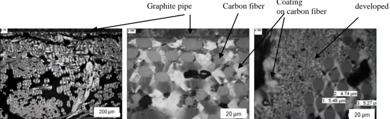
Figure 7. Micrographs of a composite produced at 50bar and 1050°C during 10 min
(sample C).
On the one hand, at both temperatures, close to the graphite pipe (Figure 7), the densification of the composite is of good quality and consists in a thick, adherent and homogeneous pyrocarbon coating around each fiber. This phenomenon can be explained by the fact that the temperature is higher in the vicinity of the graphite tube, yielding an inside-out infiltration gradient.
On the other hand, the presence of another type of carbon, resulting from homogeneous nucleation, is observed at high temperature only. It is located in the initially most porous areas of the preform. The infiltration of this distinct form of pyrocarbon compensates a larger
Graphite pipe
Carbon fibers
Pyrocarbon coating
Graphite pipe Carbon fiber Coating on carbon fiber
Homogeneous nucleation developed in the pores
9
gradient of deposit thickness around the fibers, therefore yielding similar overall amounts of degree of pore filling despite the morphological differences.
3.3 Influence of infiltration time on the densification of a preform
With temperature and initial pressure fixed at 950°C and 50 bars respectively, infiltration cycles with several durations have been run.
The first experiments show a good densification (up to 0.5 mm depth of the preform) for a short infiltration time (10 minutes). The infiltration depth is 1.5 mm after 60 min in the same conditions. However, at that moment, the densification is not yet complete, as can be seen in Fig. 8: various pores are still present between some fibers even close to the surface of the preform. Anyway, after 10 or 60 minutes, the pyrocarbon deposit is homogeneous in thickness and adherent to the fibers.
Figure 8. Cross sections of the infiltrated C/C composite fabricated at 50 bar and 950°C at
various times of the methane: left 10 minutes (sample B), right: 60 minutes (sample A).
In order to further improve the densification, additional experiments were performed, using the semi continuous feeding reactor (table 1, sample D). Five successive infiltration runs have been carried out, with a total duration equivalent in time to 42 min of a batch processing. The temperature was increased from 950°C to 1050°C between steps 3 and 4.
The use of the semi continuously fed reactor allowed the matrix densification to be greatly improved. After the five runs, the mass gain of the sample increased to 90%, whereas it had
10
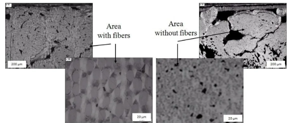
varied from 42% to 43% between 10 and 60 minutes of batch processing (table 1, samples A and B). A good densification is observed up to a depth of 1.5 mm in the preform; a thin pyrocarbon coating is still visible around each fiber up to 2.5 mm deep in the preform (figure 9).
Figure 9. Cross section micrographs of sample D prepared in five steps by semi-continuous
reactor feeding described in table 1.
Figure 9 shows several micrographs of the infiltrated sample. As for sample C (Fig. 7), two areas can be found in it: i) a fibrous area with a pyrocarbon coating around each fiber and ii) a fiber-free area where pore filling results from homogeneous nucleation.
3.4 Characterizations of the deposited pyrocarbons
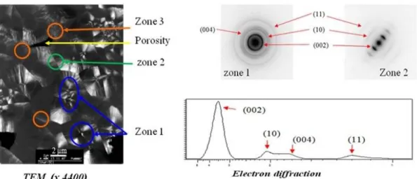
The pyrocarbon resulting from homogeneous nucleation has been observed by TEM, associated to SAED, as reported in Fig. 10. At micrometer resolution it is possible to distinguish nuclei surrounded by laminar pyrocarbon layers, with various types of textures. The topmost layer has a more granular texture. Electron diffraction confirms that the degree of organization is rather important, with neatly apparent (10) and (11) peaks; however, graphitic order is not present. In the laminar pyrocarbon layers, the SAED pattern reveals a high degree of anisotropy, with a (002) arc opening angle close to 22°.
11
Figure 10. TEM observation of sample D fiber-free area in dark field mode and selected area
electron diffraction patterns.
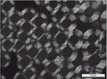
Measurements by Raman microspectrometry have been carried out on the grains produced by homogeneous nucleation, and on the pyrocarbon coatings deposited around the fibers. Figure 11a displays the spectra of both regions. Comparison with respect to known families of pyrocarbons is made by measuring the D band half-with, characteristic of the density of in-plane defects, and the D peak anisotropy ratio, characteristic of the degree of texture [27;31-32]. It is found that the pyrocarbon deposited around the fibers belongs to the Regenerative laminar (ReL) type [30], whereas the one formed by homogeneous nucleation, with a lesser anisotropy and density of defects, lies halfway between the ReL and the Smooth Laminar (SL) types. The latter fact is not surprising, taking into account that this PyC is a mixture of nuclei and laminar, highly anisotropic carbons. The rather high degree of anisotropy obtained by Raman spectroscopy is confirmed by polarized light optical microscopy, with extinction angles around 21° for the fiber coating. Figure 12 is a PLOM micrograph showing the characteristic Maltese cross edges of the ReL PyC type obtained in the deposit around the fibers.
12
Figure 11. A) Raman spectrum of sample D; the analyzed area was 1µm × 1µm × 100nm.
B) Location of PyC coating around fiber (circle) and PyC from homogeneous nucleation (triangle) on the Raman based 2D classification proposed by Bourrat et al. [27;30;33]
Figure 12. Optical microscopy micrograph under crossed polarizers of C/C composite
obtained at 1050°C.
ReL is clearly distinct from Rough Laminar (RL) though having the same degree of anisotropy and being frequently confounded with it under the global denomination of “Highly-Textured” PyC [34]
13
its formation is linked to an important degree of hydrocarbon maturation, i.e. for high residence times and low surface/volume ratios [36]. It is striking to encounter ReL here, infiltrated inside a fibrous preform: this shows that the kinetics of gas-phase maturation is much faster in the chosen supercritical conditions than in classical CVI conditions. Moreover, in CVD or in gas-phase pyrolysis of hydrocarbons, for very long residence times, homogeneous nucleation may appear. It seems to be the case in the current process at high temperatures, confirming once again the faster kinetics of the gas-phase reactions. The expected consequence would have been soot formation, but instead of this, it turns out that a limited amount of nuclei appear directly inside the largest pores and grow by laminar PyC deposition, which prevents further nucleation and helps in rapidly plugging these large pores.
4. Conclusion
The feasibility of infiltrating a fiber preform with pyrocarbon in minutes using supercritical methane has been demonstrated. A device has been set up for this purpose allowing to work under a pressure of 50-100 bar at 950-1050°C. At high temperature, the infiltration depth of the preform could reach 1.5 mm; fiber coatings were observed at up to 2.5mm in depth. A nearly full infiltration was achieved in a semi-continuous operating cycle by increasing the temperature when re-feeding the reactor with gaseous precursor. The pyrocarbons obtained by this process are of two types: one, directly deposited on the fibers, is of the Regenerative Laminar type (highly anisotropic but defect-rich); the other one, arising from homogeneous nucleation and growth, is less anisotropic due to the synthesis mechanism itself.
Considering the short infiltration times, the good infiltration quality, and the high anisotropy of the infiltrated pyrocarbon, this process has a great potential for the manufacture of carbon/carbon artifacts. For this, more process studies are necessary, including scale-up and process modeling. This is the object of undergoing work.
References
1. R. Naslain, SiC-Matrix Composites: Non-brittle Ceramics for Thermo-Structural Application, International J. Appl. Ceram. Technol. 2 (2005) 75-84.
2. H.M. Rietveld, A profile refinement method for nuclear and magnetic structures, J. Appl. Cryst. 2 (1969) 65-71.
3. J. Rodríguez-Carvajal, Recent advances in magnetic structure determination by neutron powder diffraction, Physica B: Condensed Matter 192 (1993) 55-69.
14
4. S. Sambasivan, W.T. Petuskey, Phase chemistry in the system - thermochemical review with phase - stability diagrams, J. Mater. Res. 9 (1994) 2362-2369.
5. M. Paulasto, J.K. Kivilahti, F.J.J. Van Loo, Interfacial reactions in Ti/Si3N4 and
TiN/Si diffusion couples, J. Appl. Physics 77 (1195) 4412 - 4416.
6. W.B. Hillig, Making ceramic composites by melt infiltration, Am. Ceram. Soc. Bull. 73 (1994) 56-62.
7. S. Le Ber, M.A. Dourges, L. Maillé, R. Pailler, A. Guette, Ceramic matrix composites densification by active filler impregnation followed by PIP process, Ceram. Trans. 215 (2010) 113-123.
8. J. Magnant, L. Maillé, R. Pailler, J.C. Ichard, A. Guette, F. Rebillat, E. Philippe, Carbon fiber/reaction-bonded carbide matrix for composite materials - Manufacture and characterization, J. Europ. Ceram. Soc. 32 (2012) 4497-4505.
9. Q. Le Trequesser, D. Mesguich, E. You, C. Aymonier, J.J. Watkins, Supercritical fluid deposition of compositionally uniform yttria stabilized zirconia films, The Journal of Supercritical Fluids 66 (2012) 328-332.
10. C.A. Eckert, B.L. Knutson, P.G. Debenedetti, Supercritical fluids as solvents for chemical and materials processing, Nature 383 (1996) 313-318.
11. A.I. Cooper, Polymer synthesis and processing using supercritical carbon dioxide, J. Mater. Chem. 10 (2000) 207-234
12. B.E. Richter, B.A. Jones, J.L. Ezzell, N.L. Porter, N. Avdalovic, C. Pohl, Accelerated solvent extraction: A technique for sample preparation, Analytical Chem. 68 (1996) 1033-1039
13. C. Erkey, Supercritical carbon dioxide extraction of metals from aqueous solutions: a review, Journal of supercritical fluid 17 (2000) 259-287
14. A.K. Dillow, F. Dehghani, J.S. Hrkach, N.R. Foster, R. Langer, Bacterial inactivation by using near- and supercritical carbon dioxide, Proceedings of the National Academy of Sciences of the United States of America 18 (1999) 10344-10348.
15. J. Sunarso, I. Suryadi, Decontamination of hazardous substances from solid matrices and liquids using supercritical fluids extraction: A review, J. Hazardous Mater. 161 (2009) 1-20.
16. J.M. Blackburn, D.P. Long, A. Cabañas, J.J. Watkins, Deposition of Conformal Copper and Nickel Films from Supercritical Carbon Dioxide, Science 294 (2001), 141-145
15
17. D.W. Matson, J.L. Fulton, R.C. Petersen, R.D. Smith, Rapid expansion of supercritical fluid solutions: solute formation of powders, thin films, and fibers, Indus. Engin. Chem. Res. 26 (1987) 2298-2306.
18. A. Guette, R. Pailler, N. Eberling-Fux, F. Christin, Method for the rapid densification of a porous substrate comprising the formation of a solid deposit within the porosity of the substrate, patent US2009130307.
19. L. Maillé, A. Guette, Y. Le Petitcorps, B. Reignier, Comblement des macropores d'un substrat fibreux par du pyrocarbone, 2015-07-17, patent FR3016361.
20. L. Maillé, A. Guette, Y. Le Petitcorps, J. Roger, B. Reignier, Comblement des macropores d'un substrat fibreux par nucléation en phase homogène, 2015-07-17, patent FR3016305.
21. L. Maillé, A. Guette, Y. Le Petitcorps, B. Reignier, Comblement des macropores d'un substrat fibreux avec un mélange de fluides supercritiques, 2015-07-17, patent FR3016306.
22. J.O. Andersson, T. Helander, L. Höglund, P.F. Shi, B. Sundman, Thermo-Calc and DICTRA: Computational tools for materials science, Calphad 26 (2002) 273-312. 23. P. Carlès, Thermophysical approach of supercritical fluids, in Procs. 9th Intl. Conf. on
Supercritical Fluids, Arcachon-France, 2009, F. Cansell, J. Fages, J. Mercadier, eds., ISASF/ENSTIMAC, 2009.
http://www.isasf.net/fileadmin/files/Docs/Arcachon/plenary%20lectures/CarlesArcach on2009.pdf (visited March 2,2017)
24. C. Coquelet, D. Richon, New trends in inorganic materials science using supercritical fluids: from nanopowders to more complex nanomaterials, Procs. Intl. Conf. on Supercritical fluids and mater., Arcachon-France, 2007, C. Aymonier, F. Cansell, O. Fouassier eds., 2007.
25. Z. Liu, J. Agren, M. Hillert, Application of the Le Châtelier principle on gas reactions, Fluid Phase equilibria 121 (1996) 167-177.
26. J-M. Vallerot, X. Bourrat, A. Mouchon, and G. Chollon. Quantitative structural and textural assessment of laminar pyrocarbons through Raman spectroscopy, electron diffraction and few other techniques. Carbon, 44(9):1833–1844, 2006.
27. X. Bourrat, F. Langlais, G. Chollon, G.L. Vignoles, Low temperature Pyrocarbon: a review, J. Braz. Chem. Soc. 117 (2006) 1090-1095
16
28. T. Kaplas, Y. Svirko, P. Kuzhir, Synthesis of pyrolytic carbon films on dielectric substrates, Fundamental and applied nano-electromagnetics Book Series: NATO Science for Peace and Security Series B-Physics and Biophysics (2016) 227-238 29. F. Christin, Design - fabrication and application of thermostructural composites (TSC)
like C/C - C/SiC and SiC/SiC composites. Adv. Eng. Mater. 4 (2002) 903-912.
30. X. Bourrat, A. Fillion, R. Naslain, G. Chollon, M. Brendlé, Regenerative laminar pyrocarbon, Carbon 40 (2002) 2931-2945.
31. M.L. Lieberman, H.O. Pierson, Effect of gas phase conditions on resultant matrix pyrocarbon in carbon/carbon composites, Carbon 12 (1974) 233-241.
32. H.O. Pierson, M.L. Lieberman, The chemical vapor deposition of carbon on carbon fibers, Carbon 13 (1975) 159-166.
33. P. Weisbecker, J.M. Leyssale, H.E. Fischer, V. Honkimaki, M. Lalanne, G. L. Vignoles, Microstructure of pyrocarbons from pair distribution function analysis using neutron diffraction, Carbon 50 (2012) 1563-1573.
34. B. Farbos, P. Weisbecker, H.E. Fischer, J.-P. Da Costa, M. Lalanne, G. Chollon, C. Germain, G. L. Vignoles, J.-M. Leyssale, Nanoscale structure and texture of highly anisotropic pyrocarbons revisited with transmission electron microscopy, image processing, neutron diffraction and atomistic modeling, Carbon 80 [1] (2014) 472-489. 35. G. L. Vignoles, F. Langlais, C. Descamps, A. Mouchon, H. Le Poche, N. Bertrand, N. Reuge, CVD and CVI of pyrocarbon from various precursors, Surf. Coat. Technol. 188-189 (2004) 241-249.
36. G. L. Vignoles, R. Pailler, F. Teyssandier, The control of interphases in carbon and ceramic matrix composites, Ceram. Eng. Sci. Procs. 33 [8] (2013) 11-23.