HAL Id: cea-01373983
https://hal-cea.archives-ouvertes.fr/cea-01373983
Submitted on 29 Sep 2016
HAL is a multi-disciplinary open access
archive for the deposit and dissemination of
sci-entific research documents, whether they are
pub-lished or not. The documents may come from
teaching and research institutions in France or
abroad, or from public or private research centers.
L’archive ouverte pluridisciplinaire HAL, est
destinée au dépôt et à la diffusion de documents
scientifiques de niveau recherche, publiés ou non,
émanant des établissements d’enseignement et de
recherche français ou étrangers, des laboratoires
publics ou privés.
Sensitivity of convective structures to mean flow
boundary conditions: A correlation between symmetry
and dynamics
A Pocheau, François Daviaud
To cite this version:
A Pocheau, François Daviaud. Sensitivity of convective structures to mean flow boundary conditions:
A correlation between symmetry and dynamics. Biophysical Reviews and Letters, World Scientific
Publishing, 1997, 55, pp.353-373. �10.1103/PhysRevE.55.353�. �cea-01373983�
Sensitivity of convective structures to mean flow boundary conditions:
A correlation between symmetry and dynamics
A. Pocheau1and F. Daviaud2
1Institut de Recherche sur les Phe´nome`nes Hors-Equilibre, UMR 138 CNRS, Universite´ d’Aix-Marseille I & II, S 252, Centre de Saint Je´rome, 13397 Marseille, France
2Service de Physique de l’Etat Condense´, CEA, Centre d’Etude de Saclay, 91191 Gif-sur-Yvette, France
~Received 20 June 1994; revised manuscript received 15 July 1996!
Various simple structures have been proposed for modeling the transition to time dependence of convective patterns in extended geometries. In order to further question their relevance to the dynamics of complex structures~textures!, we introduce a change of boundary conditions from both an experimental and a theoreti-cal side. It consists in keeping the same roll structure but in separating the boundaries of the mean flows from those of the roll flows. This induces negligible effects on symmetric structures ~straight rolls and foci! but dramatic changes on asymmetric ones~focus pairs and textures!, especially regarding the onset of time depen-dence. Both kinds of sensitivity to this change of boundary conditions are recovered from the Cross-Newell equations. They reveal a correlation between symmetry and dynamics that prevents symmetric structures from modeling asymmetric ones. On the opposite side, they point to focus pairs as a plausible prototype of the mechanisms of time-dependence at work in textures.@S1063-651X~96!03912-8#
PACS number~s!: 47.27.Cn, 47.20.Lz, 47.20.Bp
I. INTRODUCTION
Owing to nonlinear interactions between spatial modes, extended out-of-equilibrium systems provide fascinating but complex dynamics, still far from being understood. This has motivated a great deal of effort to model the interplay be-tween their spatial and dynamical features @1#. The present work aims at improving the selection of such models in a well-controlled dissipative system: the Rayleigh-Be´nard thermoconvection in moderate aspect ratio containers and small Prandtl number fluids.
In extended containers and close to the convective thresh-old, the convective structures generated without specific in-duction usually involve spatially disordered rolls showing curvature and defects @1#. However, in between defects, these so-called textures display much more ordered substruc-tures. Their geometry, much simpler than those of textures, are close to those displayed by the following model struc-tures: straight rolls, axisymmetrical rolls~hereafter called fo-cus!, two patches of curved rolls facing each other ~hereafter called focus pair!, and, in large aspect ratio containers, spiral rolls.
In moderately large containers, the behavior of model structures has been satisfactorily understood with a reason-able agreement between theories and experiments@1–3#. Ac-cording to theories, important qualitative differences be-tween model structures are in order however: infinite straight rolls provide large scale instabilities @4# and no intrinsic wavelength selection @5,6#: axisymmetrical rolls provide both an intrinsic selection mechanism@7,8# and a large-scale instability breaking their rotational symmetry @9,10#; focus pairs provide wavelength gradients and small-scale instabili-ties yielding the nucleation of propagating defects@11–13#.
Owing to these qualitative distinctions, one might expect that the identification of the structure suitably modeling tex-tures should be an easy task. This is not the case however for
the following reasons. First, in moderate aspect ratios, ex-periments show that the symmetry breaking undergone by foci yields steady states whose routes to time dependence actually display features similar to those observed in focus pairs: wavelength gradients and small-scale instabilities@14– 19#. Second, both foci and focus pairs exhibit at any Prandtl number almost the same onsets for time dependence, at val-ues similar to those displayed by textures@20–24#. From the experimental side, both the qualitative and quantitative fea-tures of these model strucfea-tures are thus actually so close that it is not possible to decide which of them captures the mechanisms responsible for texture behavior.
In order to improve the study of model structures and their comparison with textures, we propose to modify the boundary conditions applied to convective structures. The change consists in separating the boundaries relevant to the primary roll flows from those relevant to the secondary mean flows by translating the latter into the conductive domain. This, applied to focus pairs, has already revealed a large inhibition of time dependence through an increase of their onset by a factor of ten @25#. The purpose of the present study consists in generalizing this change of configuration to all model structures and to textures.
Two different classes of behaviors are found depending on the structure: one involving a negligible change of the onset of time dependence and the other a spectacularly large one. The first class includes straight rolls and foci; the latter contains focus pairs and textures. These quite different sen-sitivities to a change of boundary conditions show that foci and focus pairs are not physically equivalent. Furthermore, for the present moderate aspect ratio container and small Prandtl number, texture behaviors appear compatible with a modelization by focus pairs but incompatible with a model-ization by foci.
The respective origins of the two different classes are identified by analytically studying model structures. They re-veal an essential role of asymmetric spatial distortions, what-55
ever their magnitude, in this convective system.
The paper is organized as follows. Section II introduces the so-called ‘‘open containers’’ in which the boundary con-ditions are implemented. The experimental results and the theoretical analysis are presented in Secs. III and IV, respec-tively. Their consequences are drawn in Sec. V and the con-clusion of the study is reported in Sec. VI.
II. OPEN CONTAINERS
The principle of open containers is based on the second-ary mean flows generated by convection in extended geom-etries. We recall their relevance to pattern dynamics in Sec. II A before addressing the definition and the main features of open containers.
A. Mean flows
Apart from other nonvariational effects, an important phe-nomenon breaking variationality has been pointed out by Siggia and Zippelius on the Boussinesq equations @26#. It consists of mean flows spontaneously produced, at finite Prandtl number, by unbalanced Reynolds stresses, the roll flows playing the role of anisotropic fluctuations.
Usually, these flows result from roll distortion and have a scale large compared to the roll width. They have been evi-denced by tracer advection on asymmetric foci @16#. They interact with rolls by an advection forcing that may end in new pattern instabilities @29,9–13#, wave-number gradients
@28,12# , and time dependence @9–13#. They also induce
non-locality, first because, as any incompressible flow, they are nonlocally related to their sources and, second, because their advection forcing generates nonlocal interactions between rolls. All the theories proposed for model structures actually rely on them@9–13,27#.
B. Definition of open containers
Since both convective flows and mean flows are involved in convective structures, it makes sense dealing with their respective boundaries. We denote by ‘‘closed’’ containers the usual containers where the boundaries for mean flows and for convective flows are located at the same place. They are simply achieved by enclosing the convective domain by a rigid wall.
In contrast, we define as ‘‘open’’ containers the contain-ers in which these boundaries are distant from each other. Since convection is a source of mean flow at finite Prandtl number, the only achievable configuration in practice corre-sponds to a mean flow boundary located outside the convec-tive domain. This gives rise to three different regions: an inner convective zone, an outer conductive zone, and an in-terface in-between @Fig. 1~a!#.
The main difference between these domains traces back to the potential or rotational nature of mean flows. Since the self-advection of mean flows is negligible~see Appendix A!, the mean vertical vorticity only results from a balance be-tween diffusion and forcing by mean Reynolds stresses. However, in both the convective and the conductive do-mains, the horizontal scale of variations of the relevant fields is so large compared to the cell depth that the vertical diffu-sion dominates the horizontal diffudiffu-sion. Mean vertical
vor-ticity is then directly linked, at each location, to mean Rey-nolds stresses, and thus vanishes in the conductive domain. Mean flows are therefore rotational in the inner zone and potential in the outer zone@Fig. 1~a!#. Their nature within the interface is addressed in Sec. IV A 2.
C. Realization
Realizing open containers requires annihilating the roll flow in an outer zone while preserving the mean flow. Tak-ing advantage of the sensitivity of the Rayleigh number Ra to the cell depth d, Ra}d3, and of our proximity to the con-vective threshold, this selective action is obtained by slightly reducing d in a definite part of the cell. The small channel reduction then produces subcritical conditions suppressing convection but yields minor modifications on mean flows
~see Appendix D!. In this configuration, the cell domain thus
splits into a convective domain of unreduced depth d and a conductive domain of reduced depth d
8
. The roll flow FIG. 1. Sketch of open containers. ~a! The boundaries of roll flow and mean flow differ; three different domains may be defined according to the vanishing of convection, mean flow vorticityV, or none,~b! @~c!# The conductive domain is forced by inserting a thin sheet that reduces the cell depth with minor consequences for the mean flow. When the sheet is in close contact with~at some dis-tance from! the bottom plate, rolls tangential ~normal! to boundaries are stabilized.boundary corresponds to the limit of the convective domain and the mean flow boundary is located, as usual, at the lateral walls of the cell@Fig. 1~a!#.
In practice, the reduction of the cell depth has been achieved by inserting a thin sheet of cardboard at some defi-nite places of a normal cell@Figs. 1~b! and 1~c!#. Its position with respect to the bottom plate determines the roll boundary condition: in the case of a close contact @Fig. 1~b!#, rolls tangential to the sheet boundary are expected; on the oppo-site case@Fig. 1~c!#, the usual situation corresponding to rolls perpendicular to the boundary is recovered.
When contact between sheet and plate is avoided, the sheet is placed at a distance d1 of the bottom plate. Neglect-ing its thickness with respect to the cell depth d, we note
d25d2d1 its distance to the top plate. We chose d15d/4 and d253d/4 in order to provide a large depth available to mean flows. Since the vertical temperature gradient is uni-form, the threshold of convection is increased by a factor (d/d2!
45~4/3!4
in the conductive domain compared to its value in the convective one. Moreover, denoting by Ra the Rayleigh number and Rac its value at onset of convection,
the reduced Rayleigh numbers in the convective domain
«5~Ra2Rac!/Rac and in the conductive one
«
8
5~Ra8
2Rac8
!/Rac8
are related by«8
115~d2/d!4~«11!. No rolls can thus appear in the conductive domain until«'2.16. In addition, for higher values of «, the roll amplitude A
8
in the conductive domain is weakened compared to its value A in the convective domain in a ratio A8
/A5(«8
/«!1/2, smaller than 0.3 until«53.D. Validation
Since our study aims at clarifying intrinsic mechanisms of pattern dynamics, one must first ensure that the trick used to realize open containers does not modify pattern behaviors for a different cause than a change of mean flow boundary con-ditions.
Apart from the expected hydrodynamical influence, the sheet could modify convection by a thermal mean. Espe-cially, owing to the large thermal conductivity of cardboard compared to the convective fluid, here a gas, the heat current flowing within the plexiglass sidewall could be derived through the sheet well inside the cell and then modify tem-perature fields even at the border of the convective domain. To prevent this effect, the cardboard sheet has not been at-tached to the sidewalls so as to cut the heat flow coming from it. In addition, its thickness d was reduced to a small fraction of the cell depth~d5d/8! so as to minimize horizon-tal heat transport. Its length l was then sufficiently large compared to its thickness ~l/d'100! for ensuring a good thermalization with the gas and thus a large reduction of the thermal perturbation brought about by the sidewalls. Alto-gether, these conditions have likely produced less thermal perturbations than in the weakly forcing configuration stud-ied by Ahlers and co-workers in which a thicker~d5d/3! and narrower ~l/d'10! spacer tab attached to the sidewall was used @19#.
In order to experimentally control the influence of thermal perturbations on dynamics, we have studied the route to time dependence in a circular open container displaying a conduc-tive zone so narrow that hydrodynamics could only be
neg-ligibly perturbed: convective zone radius R512.5d, cell ra-dius R
8
51.1R, conductive zone extension R8
2R51.25 d. The only remaining influence could therefore only arise from thermics. However, as expected, no modification, either qualitative or quantitative, has been noticed with respect to a closed circular container of same aspect ratio R.E. Roll boundary condition
Although the sheet has a passive role with respect to pat-tern behavior, it actually provides a new roll boundary con-dition that we clarify in the following. When the sheet, what-ever its size, is placed in close contact with the bottom plate, it enhances the inhomogeneity of thermal conductivity and thus induces horizontal thermal gradients. Rolls are then ex-pected to end tangentially to the boundaries, as confirmed by experiment in Sec. III C.
When the sheet is placed in between the fluid layer, it imposes an additional rigid boundary condition at a quarter of the cell depth. Since the fundamental mode of convection involves nodes at the upper and lower plates only, it cannot satisfy this condition and therefore vanishes at the sheet boundary, as if it was a rigid wall. The same configuration as that observed in closed containers, i.e., rolls normal to boundaries is then expected. This is actually confirmed by direct observations, as shown below.
III. EXPERIMENT
The purpose of the following series of experiments con-sists in comparing, at low Prandtl number and for moderate aspect ratios, the behavior of convective structures in closed and open containers. Each of the following structures, straight rolls, foci, focus pairs, and textures, have thus been studied in both kinds of containers. For the sake of a mean-ingful comparison, closed and open containers have been made within the same experimental setup and, for each struc-ture, with the same convective domain geometry.
A. Experimental setup
The setup has already been described in detail elsewhere
@21,17#. It is designed so as to achieve and observe
convec-tion in argon gas at room temperature and at a Prandtl num-ber of 0.71.
The top and bottom horizontal plates are made of sapphire and copper, respectively. The top plate is thermally regulated by water circulation and the bottom plate by an electrical heater. The cell is made of Plexiglass and the sheet is made of cardboard. Compared to argon gas ~l51.8731024 W cm21K21at 30 bars and 300 K!, the thermal conductivity of materials are respectively 23104 ~copper!, 23103 ~sap-phire!, and 10 ~Plexiglass and cardboard! times larger.
Pattern visualization is achieved by the shadowgraph method. Owing to the low density of argon gas at room temperature, increasing the temperature gradients and the op-tical properties of the medium are necessary for enhancing the contrast of the images. This is obtained by raising the pressure to 30 bars, following a previously described method
@21,17#.
The cell depth is 1.6 mm and the critical temperature difference is 3.5 °C. Its uniformity is ensured by three
cali-brated spacers within an accuracy of 1022 mm. Measure-ments of pressure reveal its stability at better than 1%. The temperature difference between the top and bottom plates is measured by a series of thermocouples. It is electronically regulated to within 1022°C.
Images of the convective layer are made on a charged-coupled device camera by an afocal doublet of telescope-quality lens. The contrast of the images is adjusted by vary-ing the camera position and has been enhanced by image processing.
Except in the study of straight rolls ~Sec. III B!, the ge-ometries of both the mean flow boundaries and the roll flow boundaries have been taken to be circular. The former, which corresponds to the cell boundary, displays an aspect ratio R
8
~the ratio of its radius to the cell depth d) of R
8
525. The rollflow boundary is determined by the sheet boundary. Except, in a validation experiment ~Sec. II D!, its aspect ratio R has been fixed to R5R
8
/2512.5.According to the thermal diffusivity kof argon ~k50.69 cm2s21 at 30 bars and 300 K!, the vertical and horizontal thermal diffusion times in the convective domains are tv
5d2/k53.7 s andt
h5R2d2/k'10 min. Since the present
experiments aim at studying intrinsic mechanisms of pattern dynamics, only asymptotic states observed beyond transient decays have been considered. Following theoretical analysis
@8# and observations @13#, this has required waiting times of
at least R2th'25 h, unless limit cycles or stationary states
were reached. No hysteresis has been noticed on any of the structures studied.
B. Straight rolls
Outside defect cores, straight rolls may be considered as a local approximation of textures as far as roll curvature is neglected. From this point of view, they stand as the most natural candidate for modeling textures@4#. However, at low Prandtl number, closed containers have revealed a large dif-ference between the onset of time dependence of straight rolls~«'0.5! and that of textures ~«'0.1!. This is sufficent to conclude that straight rolls fail to capture the mechanisms of texture time dependence@20,21,29,30#. Although they are disqualified for modeling textures, their behavior in open containers is nonetheless interesting in understanding the sensitivity of patterns to mean flow boundary conditions. We thus report it below.
The open container is made with a cardboard sheet in-volving a rectangular hole so as to fit the geometry of straight rolls. It delimits a convective domain of dimensions 25319 in cell depth units. At the small sides of the rectangle, the sheet is put in close contact with the bottom plate so as to stabilize tangential rolls. At the large sides of the rectangle, the sheet is put at some height above the bottom plate so as to induce normal rolls. By this way, all the roll boundary conditions are compatible with straight rolls parallel to the small side of the rectangle. As expected, they give rise to a straight roll structure close to the convective threshold.
The closed container consists of a rectangular Plexiglass cell filling the entire conductive domain and is in close con-tact with the top and bottom plates. Rolls normal to all boundaries should then be induced. This tendency is how-ever inhibited by placing, along the smallest sides of the
rectangle, two thin cardboard strips in close contact with the bottom plate. Then straight rolls parallel to the smallest sides of the container are actually induced close to the convective threshold.
In both open and closed containers, straight rolls show the
same route to time dependence. It is displayed in Fig. 2 in
the case of open containers. The wave number is selected
@Figs. 2~a! and 2~c!# but, as observed in a number of closed
containers@24,17,29#, its value changes by defect nucleation each time the skewed-varicose instability is encountered
@Figs. 2~b! and 2~d!#; asymptotic states are then stationary
until an oscillatory motion of rolls induced by the oscillatory instability@4# occurs at high values of «. The only noticeable difference regarding the kind of container is thus at most quantitative, but, as shown in Fig. 2~e!, small enough to con-clude: the route to time dependence of straight rolls is inde-pendent of the mean flow boundary condition.
C. Foci
The open container is made with a cardboard sheet in-volving a circular hole so as to fit the geometry of foci. In order to generate a roll tangent to the boundary @Fig. 1~b!#, the sheet is placed in close contact with the bottom plate. The aspect ratios are R512.5 for the convective domain and
R
8
52R for the conductive one.The closed container is achieved by taking a circular Plexiglass cell filling the entire conductive domain
R,r,R
8
. Then a thin cardboard strip is placed all along its inner boundary in close contact with the bottom plate so as to induce a circular roll there.Experimental observations show a similar route to time dependence in both closed and open containers@18# ~Figs. 3 and 4!: The focus singularity first shifts as « increases, the pattern being still stationary @Figs. 3~a! and 4~a!#. The am-plitude of this off-centering is similar in both kinds of con-tainers, a bit larger in closed concon-tainers, however~Fig. 5!.
The first dynamical event appears at «50.20 in both closed and open containers and consists in defect nucleation by roll pinching at r'3R/4 @Figs. 3~c! and 4~b!#. In both configurations, two dislocations are generated and climb on a circular roll, one on the left of the off-centering direction, the other on the right. They thus rotate in opposite directions but eventually glide to the focus where they disappear, as illus-trated in Figs. 3~c!–3~f! for the open container and Figs. 4~b!–4~f! for the closed container. At this time, a roll pair has been lost. However, the focus singularity generates it back and allows the same scenario to resume. One thus ob-tains a limit cycle, as already observed in containers with similar aspect ratios@31,18,17#. An important difference be-tween containers is in order however: whereas foci show permanent oscillations in closed containers as soon as
«50.20, they are able to restabilize in open containers in
between 0.20<«<0.25 @Fig. 3~b!#.
This periodic dynamics contrasts with that reported in smaller @15# or larger aspect ratios @19,32# where no limit cycles involving defect nucleation have been observed. In particular, in the latter case, foci emit phase traveling waves but fail in reaching a stable state as soon as defects are nucle-ated: their center then moves towards the sidewalls where it disappears, leaving a textured structure.
A more accurate observation of the limit cycles reveals that, in both containers, the motion of the two dislocations is not synchronous. Near the onset of the dynamics, the dislo-cation which climbs clockwise moves quicker than the other
@Figs. 3~d! and 4~d!#, and, in closed containers, even
disap-pears sooner at the focus@Fig. 4~e!#: the period is then about 20 min, i.e., 2th. As« increases, dislocations are nucleated
closer to the sidewalls ~r'R! and are better synchronized:
the dynamics becomes more and more symmetric and the period decreases to about 3 min, i.e., 0.3th, at«50.36.
At this value of«, the limit cycles show a period doubling in both kinds of containers: dislocations are still not synchro-nous but the quickest dislocation changes at each cycle, one time that climbing clockwise, the other time that climbing counterclockwise. Labeling the clockwise direction ‘‘1’’ and the counterclockwise direction ‘‘2’’ the dynamics FIG. 2. Instability of straight rolls in an open container:GxGy525319. ~a! Stationary state: «,1.01, ~b! skewed-varicose instability:
«51.01, ~c! stationary state: 1.01,«,1.75, ~d! skewed-varicose instability: «51.75, ~e! stability diagrams in closed and open containers: «
is the reduced Rayleigh number and k the wave number of straight rolls; the symbols M, E, SV, and OSC refer to the marginal, the Eckhaus, the skewed-varicose, and the oscillatory stability curves.
may then be symbolized by the series of directions displayed by the quickest dislocation:~1,2,1,2,...!.
A period-four regime is then observed at «50.42. It is induced by the nucleation of another dislocation pair before the previous pair has disappeared. Although both pairs are simultaneously present for a while, their dislocations never collide, the slowest dislocation of the oldest pair reaching the focus center before the quickest dislocation of the youngest one. Their coupling, however, modifies the dynamical se-quence, the quickest dislocation showing the same direction during two cycles before switching to the other direction. This generates the following series of quickest dislocations:
~1,1,2,2,1,1,...!. The states referring to the simultaneous
presence of consecutive pairs of dislocations may be identi-fied by quoting the couples of their quickest dis-locations. They then correspond to the series
@~1,1!,~1,2!,~2,2!,~2,1!,~1,1!,...#, and thus to a
period-four regime.
We emphasize that the change from the period-two re-gime to the period-four rere-gime does not correspond to a modulation of the former regime ~1,2,1,2,...! but to a modification of its switching period from one dynamical state~1! to its symmetric ~2!: ~1,1,2,2,1,1,...!. This bi-furcation should therefore not be confused with a usual pe-riod doubling. As for the similar bifurcations of focus pair dynamics, its origin may trace back to symmetry breaking of the mean flow configuration@13#.
Regarding the transition to time dependence, the only dif-ference with respect to the kind of container is thus a resta-bilization of foci in open containers until«50.25. Since this delay is quite short, their route to time dependence may be considered as nearly independent of the mean flow boundary condition.
D. Focus pairs
The open and closed containers are the same as those used for foci except that the sheet is placed at a quarter of the cell height in order to allow rolls normal to boundaries @Fig. 1~c!#. The aspect ratio of the cell and of the convective do-main are still R
8
52R and R512.5. The main geometry of focus pairs is shown in Fig. 6~b! in the case of open contain-ers.Experiments reveal qualitative similarities but large quan-titative differences between the routes to time dependence of focus pairs according to the kind of container.
1. Closed container
The observed route to time-dependence is the same as that reported in the literature @21,17,19#. Focus pairs display wave-number gradients and, especially, a roll compression on the line joining foci. The largest compression is reached at the pattern center, on the central roll separating foci. Quite near the onset of convection, at «50.08, this roll becomes FIG. 3. Instability of foci in an open container: R512.5, R8525. ~a! Stable focus «,0.20. An off-centering of the focus singularity is noticeable,~b! Stationary state: 0.20,«,0.25, ~c!–~f! Time-dependent focus: 0.25,«. Notice the small asymmetry of defect climbing in ~d!.
unstable and shrinks, yielding the nucleation of a dislocation pair. These defects climb and glide to the sidewalls where they disappear, leading back to a defectless focus pair. As this structure involves less rolls than the original focus pair, all of them are less compressed and actually stable. This does not imply steadiness, however. Instead, this focus pair dis-plays a slow evolution at large scale increasing its compres-sion until a new dislocation nucleation occurs. A new cycle then repeats generating a spatiotemporal periodic dynamics. Farther from onset, till «50.45, a detailed study of the dynamics @13#, not undergone here, reveals bifurcations of the limit cycle explained by successive symmetry breakings of the mean flow field. A stationary state is then displayed in between 0.45,«,0.66 before an aperiodic persistent dy-namics occurs for 0.66,«.
Quantitative evolutions of pattern distortion on the route to time dependence are provided by local wave-number mea-surements. Figure 7 displays those performed at the most and least compressed points of steady focus pairs: the pattern center and the end of the central roll, respectively. The wave number at the pattern center grows until the vicinity of the stability boundary of infinite straight rolls is reached. Then a local instability is triggered there together with the bifurca-tion to time dependence.
FIG. 4. Instability of foci in a closed container: R512.5, R85R. ~a! Stable focus «,0.20. An off-centering of the focus singularity is noticeable, ~b! Defect nucleation: «50.20, ~c!–~e! Defect evolution by climbing and gliding, ~f! Elimination of defects at the focus singularity. Notice the large asymmetry of defect climbing in~d!.
FIG. 5. Measurement of the reduced off-centering D/R of stable foci before time dependence. D represents the distance between the center of the smallest roll and the geometrical center, R the radius of the pattern, and« the reduced Rayleigh number. The evolution is continuous from the onset of convection, in contradiction with the concept of spontaneous instability beyond some distance from the onset of convection. Black circles refer to closed containers (R
2. Open container
We describe the route to time dependence in open con-tainers for increasing «: Close to onset, «,0.1, the roll cur-vature is too weak for providing rolls normal to boundaries. At«'0.1, a dislocation spontaneously occurs by roll pinch-ing at the boundary of the central roll@Fig. 6~a!#. It remains at this place until it reaches some slightly higher value of« and then disappears by gliding to a focus. A steady focus pair is then displayed up to a surprisingly large value of «:
«50.56 @Fig. 6~b!#.
At«50.56, it undergoes a defect nucleation at the pattern center in a way similar to that displayed in a closed container
~Fig. 8!. Especially, after elimination of defects at focus
cen-ters, the new focus pair hereto involves stable rolls. How-ever, in contrast to the behavior observed in closed contain-ers, it displays no evolution at a large scale. It has thus reached a small-scale equilibrium~any roll is stable!, as well as a large-scale equilibrium~the roll patches are steady! @Fig.
6~c!# and is thus stationary. It contains one roll pair less than the previous focus pair, however.
This second focus pair remains stationary until«50.74. It then undergoes defect nucleation and restabilizes in a sta-tionary pattern again. However, in contrast with the previous case, its geometry is more complex than a focus pair and displays, as shown in Fig. 6~d!, several foci joined by grain boundaries. It remains stationary until«51.2.
Above «51.2, no stationary states have been observed, despite very large waiting times of order R2tH ~Figs. 9 and
10!. The corresponding time-dependent states will be de-scribed in Sec. III E.
Local wave numbers of steady focus pairs have been mea-sured at three locations: the pattern center kpc, the foci kf,
and the boundary of the central roll kb. The corresponding
values are displayed till «50.74 on Fig. 7.
The wave number kb is quite close to the Eckhaus insta-bility. This is consistent with the nucleation of a dislocation FIG. 6. Stationary patterns in open containers: focus pairs in~a!–~c! and texture in ~d!. R512.5, R8525. ~a! «50.03. A dislocation has been nucleated by a localized Eckhaus instability near the boundary of the upper-right quarter, ~b! «50.40. Focus pair: rolls are still perpendicular to the boundaries,~c! 0.56,«,0.60. Focus pair: one roll pair has been lost by localized instability and defect elimination. ~d! 0.74,«,1.2. Stationary texture.
at the boundary of the central roll for«'0.1 @Fig. 6~a!#. On the other hand, the wave numbers kpc and kf show similar
values. Since their difference results from the phase advec-tion by the mean flow on the axis joining the pattern center to a focus, this indicates that mean flows display an ampli-tude weaker than in a closed container and/or that they change direction on this axis.
At the transition between focus pairs~«50.56!, the wave number at the pattern center lies slightly inside the instability domain of infinite straight rolls with respect to the skewed-varicose instability~Fig. 7!. Any other local wave number is stable however. This agrees with the observation of a single local instability at the pattern center displaying a roll modu-lation analogous to a skewed-varicose distortion ~Fig. 8!. The slight difference between the marginal stabilities of straight rolls and focus pairs is not surprising owing to the finite size of the container and the spatial inhomogeneity of the structure.
Finally, as may be noticed in Fig. 7, the new focus pair displays a reduced wave-number band that fits entirely into the stable domain of straight rolls. In agreement with our
observations, its local stability is then restored.
3. Comparison between closed and open containers
In both kinds of containers, the route to time dependence of focus pairs shows similar qualitative features, especially roll compression and roll pinching. This suggests that the mechanism for time dependence is presumably the same in both cases. However, quantitative comparison of wave num-bers points out that, although the wave-number band quickly explodes in closed containers, it remains nearly constant in open ones ~Fig. 7!. The main destabilizing factor of focus pairs, roll compression, has thus been largely weakened by opening the container. This results in a large delay of the onset of persistent time dependence«0 as big as an order of magnitude: «050.74 in open containers instead of 0.08 in closed containers.
E. Textures
The closed and open containers are designed so as to al-low rolls normal to boundaries. They are thus the same as those used for focus pairs. In either closed or open contain-ers, textures @Figs. 6~d!, 9, and 10# show the following im-portant properties: except for a few marginal cases @13#, the dynamics beyond transient decay is independent of the kind of texture chosen as initial condition, of the way the onset of convection is crossed~slowly or suddenly!, and more gener-ally, on the history. This legitimizes the concept of a com-mon route to time dependence for textures. Moreover, in each kind of container, textures and focus pairs show the same route to time dependence: the same asymptotic states, the same onsets of time dependence, and the same events triggering dynamics by local instabilities and defect nucle-ation. Especially, we emphasize that textures show the same spectacular inhibition of time dependence in open containers than focus pairs, whatever their initial condition.
We now focus attention to texture behaviors in open con-tainers. As in closed containers @13#, their relaxation time to asymptotic states is quite long, usually of the order of several
Rth, except at bifurcation points where it varies in a large range: it is of the order of a few th only at the transition
between focus pairs ~«50.56! but lasts as long as Rth at the
transition to complex stationary structures ~«50.74!. This suggests that stationary attractors are weakly attracting in phase space and are few in number, so that a long wandering is necessary to reach them.
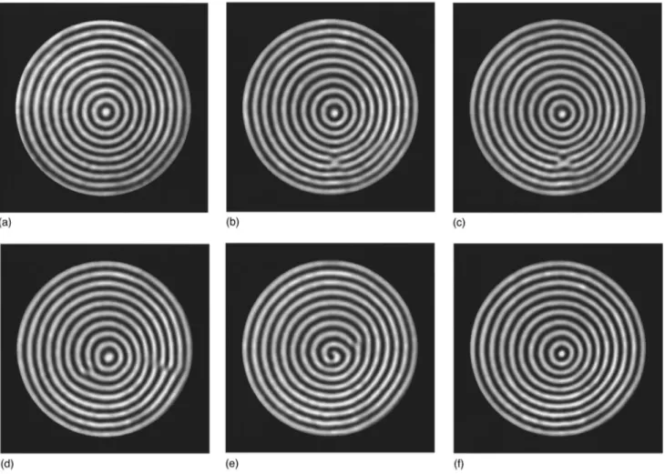
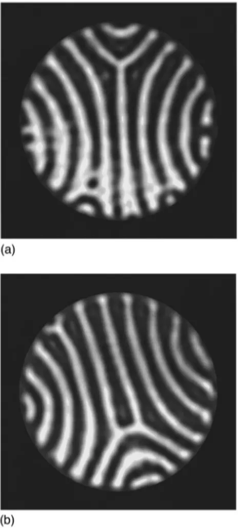
Above«51.2, a persistent time dependence of textures is displayed in open containers~Figs. 9 and 10!. Two different types of dynamics may be distinguished, depending on the scale of the destabilized spatial modes. From «51.2 to
«51.5, patterns are still in equilibrium at a large scale, but
not at a small scale. They then show localized dynamical events involving periodic cross-roll-like instabilities or grain-boundary motions, but no evolution of the large-scale geometry ~Fig. 9!. Above «51.5, pattern equilibrium is de-stroyed both at large and a small scale: large-scale erratic evolutions occur, together with defect nucleations, small-scale instabilities, and rotating spirals reminiscent of those recently observed in larger aspect ratios @33,34# ~Fig. 10!.
We finally notice that, in any dynamical regime, transient or turbulent, a phenomenon specific to open containers is FIG. 7. Stability diagram of infinite straight rolls at Pr50.7,
displaying the marginal ~M!, the Eckhaus ~E!, and the skewed-varicose ~SV! stability curves. « and k denote reduced Rayleigh numbers and wave numbers. We have plotted the local wave num-bers measured on focus pairs in closed and open containers. Black squares correspond to the band of wave numbers in a closed con-tainer. Open squares, crosses, and triangles correspond to the wave numbers in an open container, at the pattern center kpc, the focus kf, and the boundary of the central roll kb, respectively. The bold line shows the maximal wave number kmdisplayed by the solution of the Cross-Newell equations in open containers, the viscous stress of the annular sheet being taken into account. It is computed from the relations~20! and ~21!, and ~D1!–~D3! of Appendix D for p50, a523, Pr50.7,r52, andd5
1
4. As it should be reached at the pattern center, it should correspond to kpc.
displayed: focus singularities not only generate new rolls as in closed containers, but also sometimes absorb rolls.
F. Conclusion
Convective structures display two opposite sensitivities to a change of mean flow boundary conditions: ~i! quasi-invariance of spatiotemporal features including the onset of time-dependence, ~ii! large modification of spatiotemporal features including a weakening of roll compression and a spectacular delay of the onset of time-dependence.
These experimental evidences reveal two kinds of dynam-ics corresponding to two classes of structures.
(i) Boundary independent dynamics. This class includes
straight rolls and foci. It is not related to the degree of sta-bility of structures since straight rolls involve the most stable structures whereas foci show time dependence much closer to onset of convection at low Prandtl number. However, we notice that each of these model structures display continuous
symmetries of the wave-vector field: translational symmetry
for straight rolls and rotational symmetry for foci.
(ii) Boundary sensitive dynamics. This class includes
fo-cus pairs and textures. We notice that all of them display the same degree of stability: low or high in closed or open con-tainers, respectively, and at low Prandtl number. We also emphasize that none of these structures displays continuous symmetries of the wave-vector field. Only the most regular
structures, the focus pairs, involve a discrete symmetry since all substructures delimited by the central roll and the line joining foci are superposable. Focusing attention here on continuous symmetries only, we shall thus consider them as
asymmetric.
IV. ANALYSIS
This section aims at clarifying, by analytical study of model structures, the origin of the two kinds of sensitivity to boundary condition evidenced experimentally. It is based on the assumption according to which the experimental differ-ence between closed and open containers is purely hydrody-namical and only traces back to a separation of the mean flow boundary from the roll flow boundary. This is actually supported by the experimental evidence of unchanged behav-ior when these boundaries are distinct, but close to one an-other~see Sec. II D!.
A suitable framework for studying the consequences of a change of mean flow boundary conditions is the Cross-Newell equations. It will be applied for the two types of structures relevant to each kind of sensitivity: those involv-ing continuous symmetry of the wave-vector field ~hereafter called symmetric structures! and those involving none ~here-after called asymmetric structures!. The sensitivity of each of them will be derived. This will yield the link between geom-FIG. 8. Transition between stationary focus pairs in open containers:«50.56, R512.5, R8525. ~a! Localized skewed-varicose instability at the pattern center,~b!, ~c! Defect nucleation, ~d!–~f! Defect elimination at the foci.
etry and dynamics in this extended convective system. In the following, the indexes i, o, and I will refer to the inner convective zone, the outer conductive zone, and the interface in-between@Fig. 1~a!#.
A. The model
1. The Cross-Newell equations
The exact form of the large-scale equations of convection governing the coupled dynamics of the phase fieldwand the mean flow field F has been obtained by Newell, Passot, and Souli from the Boussinesq equations @10#. It closely re-sembles the Cross-Newell~CN! equations @8# previously de-rived from approximate models of convection, with negli-gible corrections close to onset of convection~«&0.5!. Since the exact equations are more complex to use than the CN equations but validate their main features, we prefer to work with the latter in the following:
t
F
]w]t 1k•FG
1“•~kB!501oS
R1D
, ~1!F52gk“•~kA2!1“~P!1o
S
1R
D
. ~2!Here k5“w is the phase gradient, A the roll amplitude,P a pressure field, and B(k,Ra,Pr!,t~k,Ra,Pr!, andg~Pr! suitable scalar functions, gbeing nearly proportional to Pr21.
The physics of these equations is recalled in Appendix A. Their validity is restricted to first order in the inverse aspect ratio 1/R. Moreover, the mean flow equation~2! neglects the mean flow dynamics and is only valid close to the convective threshold~«!1!.
2. Hydrodynamic interface
At a large scale, the interface between the inner and outer zones appears as a discontinuity of the large-scale vorticity
@Fig. 1~a!#. Of course, this is not realistic since vorticity is a
divergence-free field that cannot vanish abruptly. In fact, some vorticity sources are also generated there, either by mean Reynolds stresses or by mean flow shear.
The small extension of this interface does not allow us to neglect its vorticity contribution, since the short-scale varia-tions induced in it may yield a large vorticity magnitude. Especially, it is shown in Appendix C that it actually domi-nates the net mean vorticity generated in the convective do-main.
The different kinds of vorticity sources might be difficult to compute separately. Fortunately, their net contribution will be determined directly by using the continuity of the pressure field across the interface ~see Appendix B!.
3. Boundary conditions
We denote by n the boundary normals. Foci involve a roll tangential to boundary:
k3n50 at r5R.
Focus pairs involve rolls normal to boundary:
k•n50 at r5R.
Mean flows vanish at the impermeable boundary:
F•n50 at r5R
8
. FIG. 9. Patterns showing local dynamics ~only a part of thepattern is unsteady! and large-scale equilibrium ~pattern geometry is steady at large-scale! in an open container: 1.2,«,1.5, R512.5, R8525. ~a! Localized cross-roll instability at the bottom left of the picture,~b! Grain-boundary motion.
FIG. 10. Phase turbulence in an open container: 1.5,«, R512.5, and R8525. Notice the rotating spiral reminiscent of those observed in spiral defect chaos@33,34#.
B. Symmetric structures
1. Definition and approach
We call symmetric structures, the structures for which the wave-vector field satisfies a continuous symmetry, either translational or rotational. This selects parallel or radial wave vectors and thus straight rolls @Fig. 2~a!# or foci @Figs. 3~a! and 4~a!#.
The stability analysis of these structures turns out to solve the linearized CN equations, together with their boundary conditions, for normal modes of perturbations. Linear stabil-ity is then deduced from the resulting dispersion relation. For straight rolls, this procedure is readily achieved with Fourier modes since the partial differential equations are homoge-neous @27,8#. It is however much more complex to imple-ment in foci since the corresponding equations involve space-dependent terms. Evidence of instability is then ob-tained from integral considerations and numerical calcula-tions@9,10#.
In the following, our goal consists in comparing the linear stability analysis of symmetric structures in closed and open containers without deriving explicitly either of them. We shall first notice that their basic state of instability does not depend on the kind of container. This will lead us to focus attention to the modification brought about on mean flows by the sole change of boundary conditions. Analyzing its con-sequence on the instability spectra will show the indepen-dence of the onsets of instability with respect to mean flow boundary conditions.
2. Mean flow sources
Since mean flow sources correspond to mean Reynolds stresses, they derive from roll modulation and thus satisfy the same symmetries as the roll structure. Within the convec-tive domain, they then generate, according to Eq. ~2!, mean flows normal to roll axis in a straight roll structure and radial mean flows in foci, up to a pressure gradient. In addition, the former flows are invariant by translation along the roll axis and the latter are invariant by rotation around the focus cen-ter. Owing to these symmetries, no mean flow vorticity can be generated in both cases in the convective domain.
Within the interface, the roll direction is either normal or parallel to the roll boundary, in either straight rolls and foci and in either kinds of containers~Figs. 2–4!. The roll struc-ture therefore satisfies a translational symmetry along the interface and a reflection symmetry with respect to the inter-face normal. Since its mean Reynolds stresses must satisfy the same symmetries, they can only be a vector field parallel to the boundary normal and independent of the orthogonal direction. No field of this kind can generate vertical vorticity. We emphasize that this statement is valid in stable or un-stable regimes, since the boundary rolls stay the same any-way.
The mean flows generated by symmetric structures and by boundary rolls can thus only be potential, incompressible, and free of singularity. However, no flow of this kind can exist in a closed cell. Neither symmetric structures in stable states nor their interface in unstable states can therefore gen-erate mean flow, in any kind of container.
3. Basic state of instability
Since, whatever the kind of container, symmetric struc-tures involve no mean flow, their phase field is the same in either case. The difference between their stability analysis therefore traces back to a change not of the basic state of instability but of the mean flows. We shall denote dF, this
mean flow variation induced by the sole change of mean flow boundary conditions. We address its main features be-low.
4. Mean flow perturbation
As mean flows vanish in symmetric structures, whatever the kind of container, the mean flow modificationdF brought
about by the change of boundary conditions only results from that induced on mean flow perturbations. It is thus at least of the same order as the phase perturbationc and dis-plays, at first order inc, the same growth rate asc.
On the other hand, according to ~2!, the mean flow vor-ticity generated in the convective domain only follows from roll modulation, independently of the kind of container. This means that the change of mean flow boundary condition brings no additional vorticity in the inner zone by itself and thus that the corresponding mean flow modificationdFi can
only be a potential flow satisfying mass conservation. Both its potential and its stream function therefore satisfy a laplace equation: dFi5“(dp)5“3(jez) withD(dp)5D(j)50.
5. Dispersion relation
At first order in phase perturbation, the only difference brought about by the change of containers comes from the mean flow variation dFi through the advection term
ku•dFi, ku denoting the wave vector of the unperturbed
structure. We determine below its consequence on the insta-bility spectrum.
As the additional mean flowdFi and the phase perturba-tion chave the same growth rate, eliminating one of them from the linear stability analysis does not modify the insta-bility spectrum but provides the opportunity of focusing the analysis on essential modes. Elimination of dFi may be achieved as follows: Taking the curl to the mean flow equa-tion~2! yields an equation linking the mean flow vorticity V to the phase perturbation c. It is decoupled from dFi since
dFi drives no vorticity.
On the other hand, applying a suitable differential opera-tor P~•! to the phase equation ~1! yields a dynamical equa-tion for the phase perturbaequa-tioncthat only involves the mean flow difference dFi via P~ku•dFi!. When the basic structure
consists of straight rolls, kuis a constant vector ksex. Taking
P(•)5D~•! then yields P~ku•dFi!5ks]D~dp!/]x50. On the
other hand, when the basic structure is a focus, ku is a radial vector kfer. Taking P(•)5D(rk21f • ) yields
P~ku•dFi!5]D~j!/]u50. In both cases,dFi disappears from
the equation and, finally, from the stability analysis. According to the above statements, the mean flow differ-ence dF between containers cannot modify the dispersion
relation and thus the onset of linear instability; it only changes the shape of the unstable modes by driving an addi-tional phase distortion dc displaying the same growth rate than the other dynamical modes and yielding no mean flow vorticity. Symmetric structures therefore keep the same onset
of instability in either closed or open containers.
C. Asymmetric structures
1. Definition and approach
We call asymmetric structures the structures whose wave-vector field satisfies no continuous symmetry, either transla-tional or rotatransla-tional@Figs. 6~d!, 9, and 10#. They thus corre-spond to any structures different from straight rolls or foci and therefore involve some distortion.
Since asymmetric structures differ from straight rolls, they display wave-vector rotations. However, we emphasize that they also involve wave-number gradients: “~k•k!Þ0. Otherwise, since k is a gradient field, ~k•“!k5“~k•k!/21k
3“3k would vanish, except at the singular points where k
is not defined. The field lines of k would then be similar to the stream lines of a steady flow with no total derivative and would thus correspond to straight lines between singular points. Since an intersection of two field lines of k is a phase singularity, the only possibilities for keeping their density finite would then be either no intersection or a single one in the whole domain. The former case corresponds to a constant wave-vector field, k5ksex, and thus to straight rolls. The
latter case corresponds to a radial wave-vector field, k5kfer,
and thus to foci. Both involve continuous symmetries, in contrast with asymmetric structures.
Owing to these wave-vector gradients, asymmetric struc-tures trigger some mean flow sources which, because of the absence of continuous symmetry, generate some mean flow vorticity. They thus cannot be compensated by a pressure gradient, so that the resulting mean flows are necessarily not zero: FÞ0. This important feature contrasts with the vanish-ing of mean flow in symmetric structures and makes all the difference between the two kinds of patterns. Especially, the change of container is now suitable for modifying the mean flows of asymmetric structures and consequently their phase, even in their stable regime. Not only the mean flow pertur-bations but also the basic state of instability may then now depend on the kind of container. Compared to symmetric structures, this provides an additional opportunity of being sensitive to a change of mean flow boundary conditions.
Another important difference brought about by asymme-try is the following. As a result of phase advection F•kÞ0, mean flows, whatever their magnitude, stretch the roll wave-length and thus induce a small but continuous wave-number drift along mean flow streamlines@28,12#. Its consequences are enhanced in large aspect ratio cells since, being inte-grated over long distances, this drift may result in consider-able wave-number shifts. This important effect actually cor-responds to the accumulation of a nonlinear phase shift from rolls to rolls and thus to a secular behavior in space, the spatial cycles being provided by rolls and the secularity by the wave number increase. Following it, unstable wave num-bers may therefore be reached locally so that local instabili-ties may be triggered prior to any instability of large-scale fields. This, again, contrasts with symmetric structures where an evolution of geometry could only be generated by large-scale instabilities.
A priori, the stability analysis of asymmetric patterns
might proceed as in symmetric structures, by seeking the dispersion relation of phase perturbations around some basic
state. However, owing to the wave-number gradients, the linearized equations would involve space-dependent coeffi-cients that could likely result in a localization of the growth rate s of the perturbations: “~s!Þ0. Especially, in a WKB approximation, a local crossing of the stability boundary of rolls by extremal wave numbers would induce a local posi-tive growth rate and thus a localized instability. Motivated by this statement and by experimental observations, we chose to perform the stability analysis in two steps: first, determination of the basic state of instability and second, investigation of its local stability.
This procedure is implemented below on a model of asymmetric structure: the focus pair. It is similar to that al-ready used in closed containers@11–13# but is supplemented here by an analysis of the conductive zone, of the interface, and of their effects on the convective zone. Owing to the analytical complexity of the CN equations as far as no con-tinuous symmetry is involved, the basic state of instability is solved by a perturbative method. A relevant polynomial ex-pansion of the phase field is introduced and the resulting mean flows are determined at the same order of expansion. Both fields are then substituted into the phase equation, from which an algebraic system governing the expansion coeffi-cients is obtained. Its solution, compatible with the boundary conditions, provides the identification of the basic state of instability. Its stability at any location is finally investigated by comparison of its local wave numbers with the stability domain of infinite straight rolls, hereafter called the Busse balloon@4#.
2. Phase field
The central roll line and the line joining foci are denoted
x and y axis, respectively ~Fig. 11!. Following the
symme-tries of focus pairs with respect to them, the phase field is expanded as w~x,y!5k0~11D!y
F
12a x2 R21b y2 R21c y4 R41d x2y2 R4G
, ~3!FIG. 11. Sketch of the phase field and the coordinate frame in both closed or open containers.
where k0, the wave number selected by foci, satisfies
B(k0,«,Pr)50 @8#.
Here, a, b, c, d, and D are expansion parameters. The parameter a drives phase curvature and the remaining ones
b, c, d, and D, phase compression. In agreement with
per-turbative analysis, they are all considered much smaller than unity. Moreover, following experimental observations show-ing a weak compression compared to curvature @Fig. 6~b!#, we anticipate that b, c, d, and D are second order in a, as confirmed at the course of the derivation.
3. Mean flow field
(a) Mean flow vorticity. Expansion of Eq.~2! yields,
ac-cording to Eq.~3!, Vzi5v r2 R4sin~2u!1o
S
a2 R2D
, ~4! where v52gkoA2(ko)d, d5a2(125p)23d(11p), andp5] ln(A2)/]lnk(ko). By symmetry of the underlying
pat-tern, the polar harmonics of the mean vertical vorticity in the interfaceVzIare even but only the quadrupolar mode is reso-nant with the other modes of the problem. Disregarding the other harmonics, we thus write
VzI5
d~R!
R vIsin~2u!1O
S
d~R!
R2
D
, ~5!where d(R) is the delta function and where vI will be de-termined later. Finally, the mean vertical vorticity Vzo van-ishes in the outer zone:
Vzo50. ~6!
(b) Stream functions; potentials. Owing to the symmetries
of the pattern, the stream function j of F is sought as a second polar harmonics:j~r,u!5j~r!sin~2u!. It is obtained by integration of the Poisson equationDj52Vzwhere,
accord-ing to Eqs.~4!–~6!, Vz5Vz(r)sin~2u!:
j~r!52r2
E
0 r1 s5E
0 s t3Vz~t!dt ds2 v 12F
b r2 R21g R2 r2G
. ~7!We note thatbandg, to be determined later, drive a poten-tial flow. Owing to ~4!–~6!, j may be written in both the inner and outer zones:
r,R: ji52 v 12
F
r4 R41b r2 R21g R2 r2G
sin~2u!, ~8! r.R: jo52v 12F
~b2m11! r2 R21~g1m! R2 r2G
sin~2u! ~9! with m52F
1 213 vI vG
. ~10!We shall find it convenient to split the corresponding mean flow fields Fi5“3~jiz! and Fo5“3(joz) into a rotational
and a potential part, indexed by r and p, respectively: Fi
5Fi p1Fir, Fo5Fo p1For. We make the choice For50
and Fir5“3(jirz) wherejir is the value ofji forb5g50. The corresponding potential parts Fi p and Fo p then drive
from the following pressure fields:
r,R: Pi52 v 12
F
b r2 R22g R2 r2G
cos~2u!, ~11! r.R: Po52 v 12F
~b2m11! r2 R22~g1m! R2 r2G
cos~2u! ~12! with Fi p5¹Pi and Fo p5¹Po.(c) Mean flow field. Mean flows satisfy three boundary
conditions.
~i! Impenetrability at the cell wall: F•n50 at r5R
8
. This implies jo(R8
)50 and thus b5211m~12r24! wherer5R
8
/R.FIG. 12. Closed container:r51,b521. Sketch of ~a! the mean flow field on a square lattice~b! mean flow stream lines for l50,
20.05, 20.1, 20.15, and 20.20. Notice the back flow joining foci
and pattern center. This focalization of the mean flow is responsible for a dangerous roll compression at the pattern center.
~ii! No singularity at the pattern center. This givesg50. ~iii! Continuity of the pressure fields Pi and Po at the
interface, as derived in Appendix B. This yields m51 2 from Eqs.~11! and ~12! and, from Eq. ~10!,vI52v/3. Altogether, these constraints yield
b52~11r24!/2, g50, m51
2. ~13!
We note that the value of b changes from 21 to 212 from closed ~r51! to largely opened containers ~r@1!.
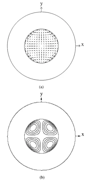
One finally obtains the following expression for the mean flow field F: r,R: Fi52 v 6 1 R4
F
r~r 21bR2!S
cos~2u! 2sin~2u!D
1r3S
0 2sin~2u!DG
1oS
a2 RD
, ~14! r.R: Fo52 v 12 R2 r3S
cos~2u!F
12 r 4 R8
4G
sin~2u!F
11 r 4 R8
4G
D
1oS
a 2 RD
. ~15!Its streamlines, parametrized byl, satisfy
r,R: r 2 R2
S
r2 R22 R4 2R8
42 1 2D
sin~2u!5l, ~16! r.R: R 2 2 R8
42r4 r2R8
4 sin~2u!5l. ~17!The mean flow fields and the mean flow stream lines are sketched in Fig. 12 for closed containers ~r51,b521! and in Fig. 13 for open containers~r52,b'21
2). A focalization of mean flows on the line joining the foci is noticeable in closed containers but is largely weakened in open ones. This difference only traces back to the potential flow driven byb. We determine below its consequences on the phase field.
4. Basic state of instability
(a) The phase boundary conditions. Within the expansion
~3!, the condition k•n50 at the roll boundary can be written:
sinu@123acos2~u!#1O(a2!50. It is always fulfilled at the central roll ~u50!, never at focus centers ~u56p/2! and never simultaneously on the whole boundary. Additional modes not taken into account in the present expansion of the phase field would thus be required to achieve it exactly. However, we emphasize that the status of this boundary con-dition is more phenomenological than analytical and, in par-ticular, has not been addressed for the large curvatures en-countered near the focus centers. We thus use it as a useful mean for estimating the curvature parameter a by imposing almost perpendicular rolls for u about p/4. We then obtain
a5231o(a). A value of order unity of a, although required to model satisfactorily the phase field, might appear incom-patible with a perturbative expansion. Our guess is that the physical mechanism of pattern destabilization derived at weak curvature is sufficiently generic to operate at large ones. Then, applying our procedure for a52
3 should be con-sidered as a quantitative extrapolation of a qualitatively cor-rect mechanism. This will be supported by the agreement between the corresponding solution and the experimental ob-servations. Another phase boundary condition is in order at the locations of largest curvaturex: the focus centers. When foci are in equilibrium, the phase advection by mean flow, of order O(a2/R), balances the phase diffusion, of order x
@k(0,6R)2ko#. Sincexis of O(1) near a focus center, this
gives k(0,6R)2ko5O(a2/R) where a5O(1) and R
5O(10) in extended cells. We then obtain k(0,6R)2ko
5o(a2) that expresses the wave-number selection by foci. Within the expansion~3!, this yields D523b25c.
FIG. 13. Open container:r52,b'2 12. Sketch of~a! the mean flow field on a square lattice~b! mean flow stream lines l50.4, 0.3, 0.2, 0.1, 0,20.02, 20.04, and 20.06 for r,R and l5n/32 with n50, 0.5, 2, 4, 6, 8, 10, and 12 for r.R. Notice the mean flow shear at the hydrodynamic interface and the low amplitude of the back flow on the line joining foci and pattern center, compared to that displayed in closed containers. Roll compression at the pattern center is weaker and time dependence is inhibited inside the Busse balloon.
(b) The basic state of instability. Introducing the mean
flow field F found in Eqs.~14! and ~15! into the phase equa-tion ~1! yields ]w ]t 5koDi
FS
6b22aD2b ad 3D
y R21S
20c2 ad 3D
y3 R4 1~10a216d2ad!y x 2 R4G
~18! with a52F
gkA 2t ]B/]kG
~ko,«,Pr!, Di52F
1 t ]~kB! ]kG
~ko,«,Pr!. ~19!As (]B/]k)(ko,«,Pr) is negative and B(ko,«,Pr)50, both variablesaand Di are positive.
We notice that each mode of the phase equation ~18! is actually involved in the phase-field expansion ~3!. This en-sures the closure of the expansion of the CN equations and enables us to rewrite them as an algebraic dynamical system, by a mode to mode identification. Solving it in steady states gives the following determination of the basic states of in-stability at second order in a:
@b,c,d15 3a 2,D,ad#5D c@ 2 3b, 1 5,22~112b!,12#, ~20! Dc5a2 a 21a~11p!. ~21! As assumed at the earliest stage, the compression param-eters b, c, d, andD are second order in a. On the other hand,
dand thereforevappear to be always positive. The constant sign of v implies, from Eq. ~14!, that the direction of F is solely governed by b in steady focus pairs. As expected, relation~20! then shows that the basic state of instability of focus pairs is parametrizedb. We emphasize that this means that it actually depends on the kind of container.
5. Local stability analysis
We consider the local wave numbers displayed by steady focus pairs and investigate whether they belong to the Busse balloon. The minimal wave numbers of the phase field ~3! are reached at the boundaries of the central roll: (x,y )
5(6R,0). They amount to k(6R,0)5ko~12a!1o(a
2! and may yield roll nucleation by a localized Eckhaus instability, actually observed experimentally@Fig. 6~a!#.
The maximal wave number kmtakes place on the y axis.
Here, k reduces to the following expression:
k~0,y!5ko
F
11DcHS
y2 R21b
D
2
2~b11!2
JG
. ~22! According to it, both the location and the value of kmdepend onb.~i! Forb521
2, km is reached at both focus centers (x,y )
5(0,0) and the pattern center (x,y)5(0,0). Then D50 and
km5ko.
~ii! For b,21
2, km is reached only at the pattern center
(x,y )5(0,0). Then D.0 and km5ko~11D!.
The first case is not dangerous since, at least for Pr.0.5,
ko lies well inside the Busse balloon up to large values of«
@35#. On the opposite side, the second case may well yield a
local instability at the pattern center for sufficiently large values of D. Since D is proportional to ~112b!, this means that the local stability of focus pairs depends on the kind of container, as analyzed below.
In closed containers, r51, b521, D5Dc, and
km5ko~11Dc!. At low Prandtl number Pr'1, Fig. 14~a!
shows thatDcgrows sufficiently fast with« to make kmcross
the stability boundaries as soon as «'0.1. Focus pairs are then locally unstable well inside the Busse balloon.
Asr grows fromr51 ~closed containers! tor5` ~open containers!, b increases from 21 to 212 and D decreases FIG. 14. Sketch of the diagram of stability of straight rolls, the Busse balloon, as a function of the Rayleigh number at a low Prandtl number ~Pr'1! ~dashed domain!. The wave number se-lected by foci, k0~«!, crosses the balloon at the ‘‘top,’’ at values of
« of the same order of magnitude as «B, the« limit of stable straight rolls. The local wave numbers of focus pairs are computed for p50, a5 23, and Pr50.7. ~a! Closed containers:b521. Focus pairs dis-play a wave-number band that crosses the Busse balloon at the ‘‘side.’’ This induces a local instability at values of «, «o, much smaller than «B: «o/«B5O~1021!. ~b! Open containers: r4@1,
b521
2. Crossing of the Busse balloon occurs near the ‘‘top,’’ at values of «, «o, of the order of its highest allowable value
«B/«B5O~1!. Time dependence is thus inhibited inside the Busse balloon.