HAL Id: hal-01475460
https://hal-univ-rennes1.archives-ouvertes.fr/hal-01475460
Submitted on 12 Jul 2017HAL is a multi-disciplinary open access archive for the deposit and dissemination of sci-entific research documents, whether they are pub-lished or not. The documents may come from teaching and research institutions in France or abroad, or from public or private research centers.
L’archive ouverte pluridisciplinaire HAL, est destinée au dépôt et à la diffusion de documents scientifiques de niveau recherche, publiés ou non, émanant des établissements d’enseignement et de recherche français ou étrangers, des laboratoires publics ou privés.
TEM quantitative characterization of short-range order
and its effects on the deformation micromechanims in a
Ti-6Al-4V alloy
P. Castany, Florence Pettinari-Sturmel, Joël Douin, Armand Coujou
To cite this version:
P. Castany, Florence Pettinari-Sturmel, Joël Douin, Armand Coujou. TEM quantitative characteri-zation of short-range order and its effects on the deformation micromechanims in a Ti-6Al-4V alloy. Materials Science and Engineering: A, Elsevier, 2017, 680, pp.85–91. �10.1016/j.msea.2016.10.020�. �hal-01475460�
TEM quantitative characterization of short-range order and its effects
on the deformation micromechanims in a Ti-6Al-4V alloy
P. Castany
a,b, F. Pettinari-Sturmel
a, J. Douin
a, A. Coujou
aa
CEMES/CNRS, Université de Toulouse, BP 94347, 31055 Toulouse Cedex 4, France
b
INSA de Rennes, UMR CNRS 6226 Sciences Chimiques de Rennes/Chimie-Métallurgie, 20
avenue des Buttes de Coësmes, 35708 Rennes Cedex 7, France
Corresponding author. +33 (0)5 62 25 78 73. florence.pettinari@cemes.fr
Abstract
Local order is evidenced in nodules of the duplex microstructure of a Ti-6Al-4V alloy using
in situ straining experiments in a transmission electron microscope (TEM). This local order is
identified to be short range order (SRO) because of the absence of superlattice diffraction
spots, which are associated with 2 (Ti3Al) precipitates and because of the formation of single
pairs of mobile dislocations, which are a signature of SRO. The strengthening effect of this
SRO is quantitatively evaluated. Qualitatively, the presence of SRO inhibits strongly the
cross-slip in nodules in comparison with dislocations gliding in lamellar colonies where no
SRO is present. The well-known strengthening effect of the core structure of dislocation in
Ti-alloy is revisited here in the presence of SRO to determine its possible influence.
Keywords: Dislocations; Short-range order (SRO); Titanium alloys; Transmission electron
microscopy (TEM); In situ straining.
1. Introduction
Titanium alloys are used in a wide range of domains requiring high mechanical strength and
low density. The Ti-6Al-4V alloy is the most used composition of these alloys for aerospace
and aeronautic applications. Ti-6Al-4V alloys are two-phase / alloys whose microstructure can be fully nodular, fully lamellar or duplex depending on thermo-mechanical treatments.
Mechanical properties of these alloys are mainly due to the majority volume fraction phase
that is the h.c.p. phase. The predominant slip systems in phase consist of a-type
Burgers vector dislocations gliding in the basal (0001) or prismatic planes [1-3]. As
in pure -titanium, the main parameter responsible for the mechanical strength of these alloys was shown to be the three-dimensionally spread core structure of a-type screw dislocations
that reduces their mobility [2,4-8]. When a stress is applied, the core of screw dislocations has
to recombine in a different metastable and glissile core structure in order to allow dislocations
to slip. The transition between these two core configurations leads thus to a high lattice
friction stress. On the other hand, the / interfaces in lamellar colonies have generally a minor role in the strengthening in comparison with the core structure of screw dislocations
[2,9-11]. This weak effect is due to the orientation relationship between the and phases that allow easily dislocations to cross these / interfaces. Short-range order (SRO) is also another possible source of the mechanical strength of Ti-6Al-4V alloys, but very few studies
deals with this point in industrial alloys. SRO was specifically evidenced to have an effect on
112 0
1 1 00
mechanical strength of binary Ti-Al model alloys with similar compositions of the phase of 6Al-4V. For example, the existence of SRO provides a significant strengthening in a
Ti-6Al (at.%) during creep tests at room temperature [12]. SRO was evidenced from neutron
diffraction in this alloy [13], but can also be detected from the dislocation arrangement after
deformation by Transmission Electron Microscopy (TEM): indeed, when there is SRO, the
deformation becomes more heterogeneous with dislocations pile-ups with sometimes paired
dislocations at the head of pile-ups as previously observed in Ti-6Al [12,14] or Ti-5Al [15]
binary titanium alloys (at.%). In other -titanium alloys, observation of pile-ups is also sometimes attributed to the presence of SRO even if this feature is just mentioned and not
investigated [16-18]. Else, the presence of ordered 2 (Ti3Al) nanoprecipitates in Ti-alloys has
been mentioned in the literature and attributed to solute partitioning in primary grains, as well as their detrimental effects on fracture toughness and low cycle fatigue [19-21].
Recently, this precipitation has been investigated in details by Radecka et al. using TEM and
atom probe tomography. In their case, superlattice diffraction spots are clearly visible in the phase [22].
Contrarily to SRO in -titanium alloys, SRO was extensively studied in Ni-based superalloys. In theses alloys, the SRO is described as nano-sized diffuse domains that lead to a high
friction impeding the glide of isolated dislocations [23]. Generally, a pair of dislocations
propagates at the head of pile-ups [23,24]. A strong difference between SRO and long rang
order (LRO) precipitates, on a “dislocation point of view”, is that LRO precipitates need
several paired dislocations to be sheared and, when they are totally sheared, individual
dislocations can glide in the plane that contained theses precipitates [25]. Several pairs of
dislocations gliding on the same plane are thus a signature of ordered precipitates, whereas a
unique pair at the head of pile-ups corresponds to SRO. In addition, in the electron diffraction
The aim of this paper is to contribute quantitatively in the understanding of SRO in Ti-6Al-4V
alloys and its effects on the mechanical strengthening and dislocations arrangement via in situ
TEM straining experiments.
2. Experimental
The material of this study is an industrial Ti-6Al-4V alloy with a duplex microstructure
composed of primary alpha nodules P and lamellar colonies S/(Fig. 1). The nodules and
lamellar colonies have roughly the same size of about 10 µm and similar volume fractions.
The b.c.c phase is found mainly is lamellar colonies with a total volume fraction of about 3% [2,11]. Because no effect of short-range order was evidenced in secondary alpha platesS
in lamellar colonies, this paper focus on primary alpha nodulesP.
Specimens for in situ TEM straining experiments were first mechanically polished and then
thinned down by twin-jet electropolishing at a temperature of -15°C. The electrolyte used was
the A3 solution commercialized by STRUERS. TEM post mortem observations were also
performed in order to compare in situ results with the microstructure of samples deformed
macroscopically in tension.
In situ experiments were performed at room temperature with a Gatan straining holder in a
200 kV JEOL 2010 TEM equipped with a SIS CCD camera for video-rate recording.
Burgers vectors of dislocations were determined by the g.b=0 invisibility criterion and slip
planes were characterized by the analysis of slip traces left on the surfaces of specimens
during in situ straining experiments. All measurements of distances between dislocations were
theses measurements were done during in situ experiments on moving dislocations, the
accuracy of measurement is lower than for conventional TEM observations. Depending on the
measurement, the accuracy is then of about 10-20%.
3. Results
All moving dislocations observed during in situ straining experiments have a-type Burgers
vectors and glide mainly in prismatic or basal planes depending on the crystallographic
orientation of the primary P nodule observed. Cross-slip is rarely observed contrarily to
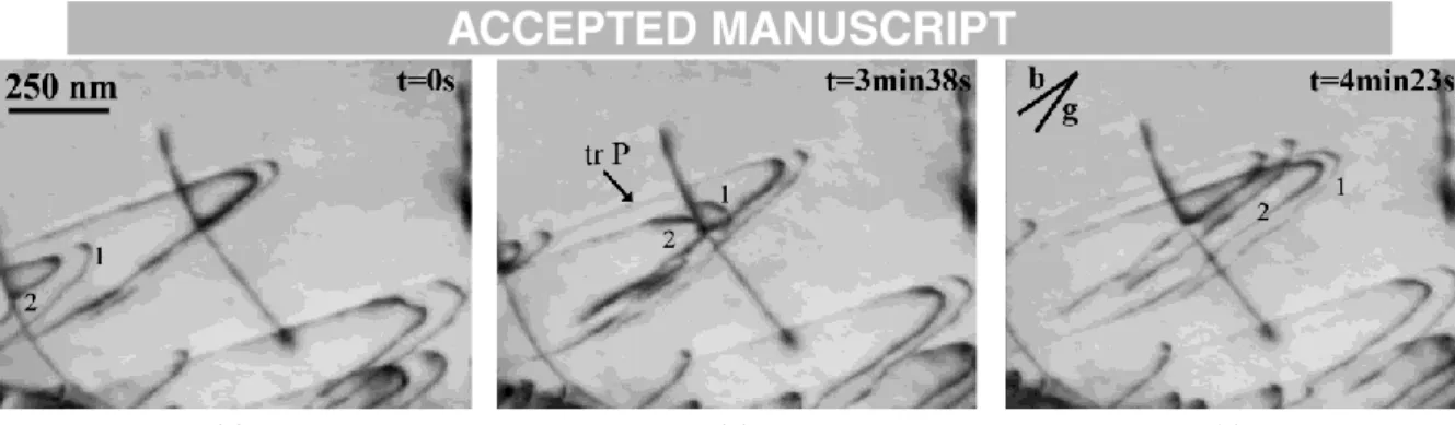
previous experiments performed in the phase of lamellar colonies [2]. An example of the typical motion of dislocations in a P nodule is shown in Fig. 2. The projection of their
Burgers vector is indicated by the line labelled “b”. Dislocations appear clearly to glide
paired: two dislocations, numbered 1 and 2, glide together in a correlated way across the
grain. Screw segments remain roughly straight and move together, as well as curved
non-screw segments. Non-non-screw segments have a relatively steady motion, whereas straight non-screw
segments have a more jerky motion as observed previously in the phase of lamellar colonies of the same alloys [2]. All dislocations in this grain glide in the same set of prismatic planes
whose trace is indicated in Fig. 2b. Slip traces are rigorously straight indicating that cross-slip
does not occur. Fig. 3 shows the same grain under different diffracting conditions after in situ
straining: almost all dislocations remain paired even when the stress is removed. Paired
dislocations are also observed for basal slip. For example, two pairs of dislocations, numbered
1 and 2 in Fig. 4, has a correlated motion for their screw segments as well as non-screw ones.
The distance separating both paired dislocations varies during their motion during in situ
experiments: an example is given in Fig. 5 wherein the spacing between paired dislocations is
(Fig. 5a) or basal plane (Fig. 5b). The average values taken from several pairs are summarized
in Table 1: this spacing is almost independent of the slip plane and is larger for edge segments
than for screw segments. The values measured after in situ straining experiments are also
reported in Table 1 with a relative uncertainty of about 20% as the measurements have been
performed on dynamic sequences. This shows that the spacing remains constant after the
stress is removed for screw segments and slightly decreases for edge segments.
The measurement of velocities of paired dislocations moving under stress during in situ
straining shows that the screw segments move almost twice slower than edge segments (Table
2). In the prismatic plane, both edge and screw segments moves faster than in basal plane.
This difference is most probably due to a different stress depending on the experiment. But, as
the ratio between the velocities of edge and screw segments is exactly the same whatever the
experiment, one can deduce that the velocity is independent of the slip plane.
In some P nodules, dislocations form large pile-ups instead of single pairs of dislocations.
Such pile-ups are due to Frank-Read sources operating inside the grains. An example is given
in Fig. 6, where a mobile segment rotates around an anchoring point (arrowed in the second
frame). At t=0s, four screw segments are numbered 1, 2, 3 and 4. The segment numbered 4 is
mobile and rotates around the anchoring point of the source. On the next frame of the
recorded video, at t=0,04s, the segment numbered 4 has rotated and is moving quickly toward
the right (that is why it is invisible in this frame). After this rotation, the new segment rotating
around the anchoring point is numbered 5. In the last image, the segment numbered 4 is
visible and the segment numbered 5 has made another rotation leaving a new screw segment
toward the left and the right of the source. At the head of this pile-up, the two first
dislocations are clearly paired whereas further dislocations not (Fig. 7). Contrarily to the
paired dislocations presented in Fig. 2 or Fig. 4, only screw segments can be observed here
Fig. 6 correspond to a prismatic plane. After this source has generated several tens of
dislocations, some dislocations cross-slip to a first-order pyramidal plane, that is highlighted
by a change in the orientation of the slip traces (Figure 8).
Observations of specimens after macroscopic tensile tests up to 0.3% of plastic strain are
reported in Fig. 9. Dislocations arrangements are very similar to the previous in situ
observations: in some nodules, dislocations appear to be paired (pairs numbered 1, 2 and 3 in
Fig. 9a) whereas in other nodules, dislocations form large pile-ups (Fig. 9b). Dislocations in
Fig. 9 have a-type Burgers vectors. In situ observations are thus consistent with the behaviour
of dislocations during the macroscopic deformation.
4. Discussion
In all nodules observed, moving dislocations have a-type Burgers vectors and glide in basal or
prismatic planes that are the main slip systems in -titanium alloys [1-3,26]. The activated slip systems during in situ straining experiments follow the Schmid law according to previous
studies [1], i.e.:
- basal slip is only observed when prismatic slip systems have lower Schmid Factors (example
in Fig. 4);
- prismatic slip is activated even if basal or pyramidal slip systems have similar Schmid
factors (examples in Fig. 2 and Fig. 6).
Cross-slip is only observed in large pile-ups when several tens of dislocations are piled-up
(Fig. 8). In this specific configuration, the Schmid factors of both prismatic and pyramidal
impeded to glide in their initial prismatic plane because of the relatively high density of
previous dislocations in this plane. This observation is in contrast with previous observations
in the phase in lamellar colonies of the same alloy wherein multiple cross-slip frequently occurs leading to wavy slip traces [2]. Moreover, in nodules, cross-slip is never observed
when dislocations are paired and the slip traces are straight for paired dislocations and
pile-ups. Cross-slip is thus not as frequent in P nodules than in lamellar colonies. In -titanium
alloys, inhibition of cross-slip is frequently attributed to the presence of short-range order
(SRO) that leads to a heterogeneous deformation constituted of dislocations pile-ups
[12,14,15].
Classically, at least one pair of dislocations has to glide at the head of pile-ups in the presence
of SRO because of the influence of the chemical fault that formed after the passage of a first
dislocation. In alloys wherein SRO is clearly identified such as Ni-based superalloys, pairs of
dislocations lie at the head of pile-ups, which mainly contain numerous dislocations
[24,27-30]. In titanium alloys, a few studies have reported the presence of such pairs in a binary
Ti-6Al alloy [12,14] wherein SRO was evidenced from neutron diffraction [13].
As a unique pair of dislocations at the head of pile-ups has been observed during our
experiments (Fig.7), and no superlattice diffraction spot has been identified, it can be
unambiguously attributed to the presence of SRO in nodules. After the glide of the leading pair of dislocations, the SRO is sufficiently destroyed to allow single dislocations to glide in
the same slip plane. The slip plane is then softened and further dislocations can glide more
easily in this plane (without being paired) than in another slip planes leading to a
heterogeneous deformation. If an intragranular source is activated, several dislocations can
thus glide in this softened plane and lead to the formation of large pile-ups (Fig. 6). However,
presence of SRO. Thus, only a unique pair of dislocations is observed to glide in a correlated
way. The presence of such pairs is also due to the presence of SRO because, if there is no
SRO, only isolated dislocations should be observed. This unique feature, never observed
previously, occurs when intragranular sources are not activated in nodules that deformed by
dislocations emitted from / interfaces. Emission from / interfaces was frequently observed in lamellar colonies of the same alloy [2], but only single dislocations are emitted in
lamellar colonies instead of pairs like in nodules. This difference in dislocation behaviour
between the primary nodules and the secondary phases may be attributed to the difference in SRO (presence or not), which is directly connected with a slight difference in Al content.
An attempt was made to identify any difference in chemical composition between the
primary nodules and the secondary ones using Electron Energy Loss Spectroscopy, but the difference has not been detectable, meaning this difference is very low. But there could be
one as the precipitation of the phases appear at different step during the thermomechanical elaboration process.
In pile-ups, dislocations are only of screw character that is due to their specific core structure
that lowers the mobility of screw segments in comparison with non-screw ones [2,4-8]. A
consequence is that non-screw segments move quickly out of the specimen during in situ
TEM straining [2,5]. In lamellar colonies of the same alloy, non-screw segments was
estimated to glide at least 100 times faster than screw segments [2]. A similar feature is
observed for dislocations forming pile-ups in P nodules (Fig. 6) that suggests the presence of
SRO in these nodules does not affect the velocity and the behaviour of dislocations in
comparison with lamellar colonies except the formation of pile-ups. However, in nodules that
deform with single pairs of dislocations (Fig. 2 and Fig. 4), the situation differs because
2). In these nodules, the presence of SRO affects significantly the motion of non-screw
segments. On the other hand, the motion of screw dislocations seems not greatly influenced
by the presence of SRO and their motion is still mainly controlled by their core structure. This
result suggests that there is some fluctuation of SRO depending on each nodule. Such
micrometer-scale fluctuations of SRO were already observed in Ni-based alloys [24]. This
difference of microstructure of deformation (pile-ups or single pairs of dislocations) is also
observed in macroscopically deformed specimens (Fig. 9).
In this Ti-6Al-4V alloy, there is strong differences in the behaviour of dislocations depending
on whether they glide in P nodules or in phase of lamellar colonies (see Ref. [2] for results
in lamellar colonies):
- pile-ups or pairs of dislocations in nodules instead of single dislocations in lamellar
colonies;
- very rare cross-slip in nodules (straight slip traces) instead of extensive cross-slip in lamellar
colonies (wavy slip traces);
- ratio between edge and screw segment velocities of about 2 in nodules (with dislocations
pairs) instead of more than 100 in lamellar colonies.
These characteristics show unambiguously that the presence of SRO is only significant in
nodules. In the phase of lamellar colonies, there is most probably no SRO or, if there is, its magnitude is too weak to have any effect on the behaviour of dislocations. This difference in
SRO can only be due to a slight difference in the chemical composition of the phase in lamellar colonies and in nodules. Indeed, it is well known that in such duplex microstructure,
an alloying element partitioning can take place leading to a enrichment of stabilizing elements in nodules to the detriment of lamellar colonies [31]. In Ti-6Al-4V alloys, stabilizing elements are aluminium and oxygen that are both able to order: in binary Ti-Al
alloys, SRO is due to the ordering of aluminium atoms [12,14,32] whereas ordering of oxygen
atoms is also reported in pure titanium with high oxygen content [33]. Moreover, a combined
effect of ordering of both aluminium and oxygen (as impurity content) is also observed in
some alloys [31,34]. In P nodules, the oxygen and aluminium concentration is thus
sufficiently higher than in lamellar colonies in order to promote the formation of SRO.
In systems wherein SRO has been deeply investigated such as Ni-based superalloys,
quantitative analyses have been carried out from the position of moving dislocations during in
situ TEM straining experiments, allowing to evaluate the energies associated with SRO
[24,35,36]. A similar approach can be used for pairs of dislocations in Ti-6Al-4V like those in
Fig. 2 and Fig. 4. All the forces exerted on each dislocation of a pair are summarized in the
Fig. 10. Some of these forces are the same for both dislocations of the pair:
- the applied stress ba, where b is the Burgers vector and a the applied stress;
- the friction stress bSS due to the solid solution friction of alloying elements (this force is
assumed to be the same for each dislocation of the pair);
- the elastic interaction force A/X between both dislocations of the pair, where A is a constant
depending on the character of the dislocation and X the spacing between both dislocations.
In addition, the glide of the first dislocation of the pair (labelled 1 in Fig. 10) destroys
partially the SRO and creates behind a planar fault known as “diffuse antiphase boundary”
(DAPB) [29]. An energy 1 is thus associated with this fault for the first dislocation. The glide
of the second dislocation of the pair (labelled 2 in Fig. 10) destroys partially the remaining
SRO and creates a new fault with the associated energy 2.
The equilibrium of each dislocation can thus be given by the following equations:
( ) (1)
The equations (1) and (2) corresponds to the first and the second dislocation respectively. It is
assumed that dislocations are in quasi-static equilibrium and that they are straight and
infinitely long, i.e. the elastic interactions between each segment of the same dislocation are
neglected. As the structure of the head of a pile-up has been demonstrated to be not
significantly affected by the free surfaces of the thin foil [35], this aspect is also neglected in
this paper in order to simplify the problem. These equations are valid for screw and edge
segments with the condition to use the correct value of the constant A. The values of this
constant are denoted AS for screw segments and AE for edge segments and are expressed as:
(3)
( ) (4)
Where is the shear modulus, is the Poisson’s ratio with a value of about 0,33 and b is the Burgers vector with a value of 0.292 nm. As a consequence, the ratio between the spacing of
screw segments and edge ones can be calculated to be only a function of :
From the data of Table 1, the average experimental values of this ratio under stress are
calculated to be 0.64 in the prismatic plane and 0.57 in the basal plane. These values are
sligthly lower than the theoretical value due to the effect of the core structure of screw
segments that is not taken in account in the model used. Indeed, the core structure of screw
segments acts as an intrinsic anchoring that impedes their motion and in turn increases the
spacing between both screw segments of the pair. However, the theoretical and experimental
values are quite close that validates the simple model used to represent the dislocation pair.
For pile-ups in Ni-based alloys, it was previously calculated that during an in situ TEM
friction stress SS. Consequently, the difference (a - SS) is about zero or has a very low value
that can be neglected [35]. The DAPB energy of each dislocation of the pile-up can thus be
calculated from the elastic interaction forces due to all dislocations of the pile-up [35]. In the
specific case when the pile-up is only constituted of a unique pair of dislocations (Fig. 2 and
Fig. 4 for example), the relationship (a - SS) = 0 can not be established because, in pile-ups,
this relationship is calculated from the last dislocation of the pile-up that is assumed to move
freely in the slip plane. However, in some rare cases, a third dislocation is observed to glide
freely in the same plane of a pair with a distance until several micrometers from the pair. In
turn, the difference (a - SS) can also be assumed to be near zero when the pile-up is
constituted of a sole pair of dislocations. The equations (1) and (2) lead thus to conclude that
1 is almost equal to the elastic interaction forces between both dislocations of the pair and
that 2 is equal to zero or has a very low value in comparison with 1. In other words, that
means SRO does not change any longer after the glide of two dislocations. As the value of 2
is sufficiently low, no further dislocations are needed in the pile-up to allow the first pair of
dislocations to glide: single pairs of dislocations can thus be observed instead of pile-ups of
several dislocations. Using the value of the spacing of edge dislocations in Table 2 (that is the
same for both prismatic and basal planes), the value of 1 can be calculated as 11.6 mJ.m-2,
which corresponds to a stress 1/b equivalent to 40 MPa. As the core structure of dislocations
has a strong influence on the dislocation screw segments, it may affect their position and thus
the determination of the value of 1 for screw dislocation. Indeed, the high lattice friction
stress due to this core structure is not taken in account in the model used. To avoid this core
structure effect, the value of 1 obtained only from edge dislocations has thus to be considered
as the accurate value.
In Ni-based alloys, the value of 1 was measured to be about 30 mJ.m-2 [24,35], i.e. more than
pairs can be observed in the Ti-6Al-4V alloy whereas only pile-ups with one pair at their head
are observed in Ni-based alloys. This indicates also a low degree of SRO, and may explain
why SRO is present in nodules and not in lamellar phases: the difference in chemical composition is very slight and induces a weak SRO.
5. Conclusion
As a summary, the presence of SRO in P nodules of a Ti-6Al-4V alloy is evidenced by the
formation of pile-ups or pairs of dislocations during in situ TEM straining experiments. It has
been quantitatively evaluated to be weak and has been distinguished from 2 nanoprecipitates.
SRO is not present in lamellar colonies due to a probable partitioning of alloying elements
that enriches the nodules in stabilizing elements. These elements, aluminium and oxygen, promote the formation of SRO.
Dislocations are observed to be preferentially elongated along their screw direction as in
lamellar colonies because their mobility is mainly controlled by their core structure, even with
SRO. However, SRO affects significantly the behaviour of dislocations by:
- inhibiting the cross-slip;
- promoting the formation of pile-ups or pairs of dislocations (depending on the type of
dislocation source operating in the nodule);
- reducing strongly the velocity of edge segments of paired dislocations.
From the measurement of the spacing between paired dislocations, the diffuse antiphase
boundary (DAPB) energy 1 is evaluated to 11.6 mJ.m-2. This DAPB energy is due to the fault
created when a single dislocation glide in the short-range ordered lattice. The resistance
two dislocations, moving in a correlated way, are needed to overcome the resistance of this
fault. SRO is thus identified to be an additional cause of the strength of Ti-6Al-4V alloys.
References
[1] F. Bridier, P. Villechaise, J. Mendez, Analysis of the different slip systems activated by tension in a α/β titanium alloy in relation with local crystallographic orientation, Acta Mater.
53 (2005) 555-567.
[2] P. Castany, F. Pettinari-Sturmel, J. Crestou, J. Douin, A. Coujou, Experimental study of
dislocation mobility in a Ti-6Al-4V alloy, Acta Mater. 55 (2007) 6284-6291.
[3] S. Zaefferer, A study of active deformation systems in titanium alloys: dependence on
alloy composition and correlation with deformation texture, Mater. Sci. Eng. A 344 (2003)
20-30.
[4] S. Naka, L.P. Kubin, C. Perrier, The plasticity of titanium at low and medium
temperatures, Philos. Mag. A 63 (1991) 1035-1043.
[5] S. Farenc, D. Caillard, A. Couret, An in situ study of prismatic glide in α titanium at low
temperatures, Acta Metal. Mater. 41 (1993) 2701-2709.
[6] D.J. Bacon, V. Vitek, Atomic-Scale Modeling of Dislocations and Related Properties in
the hexagonal-Close-Packed Metals, Metall. Mater. Trans. A 33 (2002) 721-733.
[7] M. Aoki, D. Nguyen-Manh, D.G. Pettifor, V. Vitek, Atom-based bond-order potentials for
modelling mechanical properties of metals, Prog. Mater. Sci. 52 (2007) 154-195.
[8] J. Douin, P. Castany, F. Pettinari-Sturmel, A. Coujou, Direct measurement of the variation
[9] S. Suri, G.B. Viswanathan, T. Neeraj, D.H. Hou, M.J. Mills, Room temperature
deformation and mechanisms of slip transmission in oriented single-colony crystals of an α/β
titanium alloy, Acta Mater. 47 (1999) 1019-1034.
[10] M.F. Savage, J. Tatalovich, M.J. Mills, Anisotropy in the room-temperature deformation of α-β colonies in titanium alloys : role of the α/β interface, Philos. Mag. 84 (2004)
1127-1154.
[11] P. Castany, F. Pettinari-Sturmel, J. Douin, A. Coujou, In situ transmission electron
microscopy deformation of the titanium alloy Ti-6Al-4V: Interface behaviour, Mater. Sci.
Eng. A 483-484 (2008) 719-722.
[12] T. Neeraj, M.J. Mills, Short-range order (SRO) and its effect on the primary creep
behavior of a Ti-6wt.%Al alloy, Mater. Sci. Eng. A 319-321 (2001) 415-419.
[13] T. Neeraj, Low temperature creep of titanium alloys: microstructure, deformation
mechanisms and modeling, PhD Dissertation, The Ohio State University.
[14] T. Neeraj, D.-H. Hou, G.S. Daehn, M.J. Mills, Phenomenological and microstructural
analysis of room temperature creep in titanium alloys, Acta Mater. 48 (2000) 1225-1238.
[15] L. Xiao, Y. Umakoshi, Planar dislocation bands formed in Ti-5at.%Al single crystals
deforming by double prism slips, J. Mater. Sci. Lett. 21 (2002) 517-519.
[16] A. Ambard, L. Guétaz, F. Louchet, D. Guichard, Role of interphases in the deformation mechanisms of an α/β titanium alloy at 20 K, Mater. Sci. Eng. A 319-321 (2001) 404-408.
[17] B.C. Odegard, A.W. Thompson, Low Temperature Creep of Ti-6Al-4V, Metal. Trans. A
5 (1974) 1207-1213.
[18] D.J. Truax, C.J. McMahon, Plastic behaviour of titanium-aluminium alloys, Mater. Sci.
Eng. 13 (1974) 125-139.
[20] S. Hardt, H.J. Maier, H.J. Christ, High-temperature fatigue damage mechanisms in near-α titanium alloy IMI 834, Int. J. Fatigue 21 (1999) 779-789.
[21] J. Kumar, S. Padma, B. Srivathsa, N.V. Rao, V. Kumar, Evolution of damage in near α
IMI-834 titanium alloy under monotonic loading condition: A continuum damage mechanics
approach, J. Eng. Mater. Tech. 131 (2009) 0310121-0310126.
[22] A. Radecka, J. Coakley, V.A. Vorontsov, T.L. Martin, P.A.J. Bagot, M.P. Moody, D.
Rugg, D. Dye, Precipitation of the ordered α2 phase in a near-α titanium alloy, Scripta Mater.
117 (2016) 81-85.
[23] F. Pettinari, M. Prem, G. Krexner, P. Caron, A. Coujou, H.O.K. Kirchner, N. Clement, Local order in industrial and model γ phases of superalloys, Acta Mater. 49 (2001)
2549-2556.
[24] F. Pettinari-Sturmel, J. Douin, A. Coujou, N. Clément, Characterisation of short-range
order using dislocations, Z. Metallkd. 97 (2006) 200-204.
[25] R. Glas, M. Jouiad, P. Caron, N. Clement, H.O.K. Kirchner, Order and mechanical properties of the γ matrix of superalloys, Acta Mater. 44 (1996) 4917-4926.
[26] M.F. Savage, J. Tatalovich, M. Zupan, K.J. Hemker, M.J. Mills, Deformation
mechanisms and microtensile behavior of single colony Ti-6242Si, Mater. Sci. Eng. A
319-321 (2001) 398-403.
[27] J. Olfe, H. Neuhäuser, Dislocation groups, multipoles, and friction stresses in
alpha-CuZn alloys, Phys. Status Solidi A 109 (1988) 149-160.
[28] V. Gerold, H.P. Karnthaler, On the origin of planar slip in f.c.c. alloys, Acta Metall. 37
(1989) 2177-2183.
[29] P. Schwander, B. Schönfeld, G. Kostorz, Configurational energy change caused by slip
[30] J. Plessing, C. Achmus, H. Neuhauser, B. Schonfeld, G. Kostorz, Short-range order and
the mode of slip in concentrated Cu-based alloys, Z. Metallkd. 88 (1997) 630-635.
[31] G. Lütjering, J.C. Williams, Titanium, Springer, 2007.
[32] U. Lienert, M.C. Brandes, J.V. Bernier, J. Weiss, S.D. Shastri, M.J. Mills, M.P. Miller, In
situ single-grain peak profile measurements on Ti-7Al during tensile deformation, Mater. Sci.
Eng. A 524 (2009) 46-54.
[33] J.C. Williams, A.W. Sommer, P.P. Tung, The influence of oxygen concentration on the internal stress and dislocation arrangements in α titanium, Metal. Trans. A 3 (1972)
2979-2984.
[34] G. Welsch, W. Bunk, Deformation modes of the alpha-phase of Ti-6Al-4V as a function
of oxygen concentration and aging temperature Metal. Trans. A 13 (1982) 889-899.
[35] G. Saada, J. Douin, F. Pettinari-Sturmel, A. Coujou, N. Clément, Pile-ups in thin foils:
application to transmission electron microscopy analysis of short-range-order, Philos. Mag. 84
(2004) 807-824.
[36] F. Pettinari-Sturmel, A. Coujou, N. Clément, The fluctuation of short-range order
evidenced by mobile dislocations in the γ-phase of a nickel-based superalloy, Mater. Sci. Eng.
Figure Captions
Fig. 1. Low magnification TEM micrograph of the duplex microstructure consisting of primary alpha nodules P and lamellar colonies S/.
Fig. 2. Paired dislocations gliding in prismatic planes during in situ straining; a slip trace at the surface of the specimen is indicated by (tr P).
Fig. 3. Same grain as in Fig. 2 observed after in situ straining experiments when the stress is
Fig. 4. Paired dislocations gliding in basal planes during in situ straining; a slip trace at the surface of the specimen is indicated by “tr B”.
Fig. 5. Example of the distance between two paired dislocations as a function of the average position of the pair of dislocations during in situ straining for prismatic slip (a) and basal slip (b). The distance have been evaluated with a relative uncertainty of 20%.
Fig. 6. Planar prismatic slip during in situ straining with a dislocation source composed of a mobile dislocation segment rotating around an anchoring point (straight arrow); the circular arrow indicates the next displacement of the mobile dislocation.
Fig. 7. The two first dislocations of the pile-up of the Fig. 6 are paired.
Fig. 8. Cross-slip from prismatic to first-order pyramidal plane; the trace of the initial prismatic slip plane is indicated by a dashed line and labelled “trace P”; the trace of the first-order pyramidal plane is labelled “trace 1”.
Fig. 9. Microstructure of macroscopically deformed specimens showing paired dislocations (a) and planar slip (b) in prismatic planes.
Fig. 10. Schematic representation of the forces exerted on both dislocations of a pair under an applied stress (the dislocations move from left to right).
Fig. 1. Low magnification TEM micrograph of the duplex microstructure consisting of primary alpha nodules P and lamellar colonies S/.
Fig. 2. Paired dislocations gliding in prismatic planes during in situ straining; a slip trace at the surface of the specimen is indicated by (tr P).
Fig. 3. Same grain than in Fig. 2 observed after in situ straining experiments when the stress is removed.
Fig. 4. Paired dislocations gliding in basal planes during in situ straining; a slip trace at the surface of the specimen is indicated by “tr B”.
Fig. 5. Example of the distance between two paired dislocations as a function of the average position of the pair of dislocations during in situ straining for prismatic slip (a) and basal slip
(b). The distance have been evaluated with a relative uncertainty of 20%.
dista nce (n m) position (nm) screw edge dista nce (n m) position (nm) screw edge (a) (b)
Fig. 6. Planar prismatic slip during in situ straining with a dislocation source composed of a mobile dislocation segment rotating around an anchoring point (straight arrow); the circular
Fig. 8. Cross-slip from prismatic to first-order pyramidal plane; the trace of the initial prismatic slip plane is indicated by a dashed line and labelled “trace P”; the trace of the
Fig. 9. Microstructure of macroscopically deformed specimens showing paired dislocations (a) and planar slip (b) in prismatic planes.
Fig. 10. Schematic representation of the forces exerted on both dislocations of a pair under an applied stress (the dislocations move from left to right).
Table 1. Average spacing between paired dislocations, for screw and edge segments respectively, in prismatic and basal planes during in situ straining (with stress) and post
mortem observations (without stress); the standard deviation is also indicated for each
measurement.
During in situ straining Post mortem observations Average spacing (nm) Standard deviation (nm) Average spacing (nm) Standard deviation (nm) Prismatic plane screw 45 21 45 15 edge 70 24 60 12 Basal plane screw 40 15 40 18 edge 70 19 60 23
Table 2. Average velocities of paired dislocations and ratio between edge and screw segment velocities in both prismatic and basal planes.
Edge velocity (nm.s-1) Screw velocity (nm.s-1) Ratio Prismatic plane 5.5 2.4 2.3 Basal plane 2.3 1.0 2.3