HAL Id: hal-01376573
https://hal.sorbonne-universite.fr/hal-01376573
Submitted on 5 Oct 2016
HAL is a multi-disciplinary open access
archive for the deposit and dissemination of
sci-entific research documents, whether they are
pub-lished or not. The documents may come from
teaching and research institutions in France or
abroad, or from public or private research centers.
L’archive ouverte pluridisciplinaire HAL, est
destinée au dépôt et à la diffusion de documents
scientifiques de niveau recherche, publiés ou non,
émanant des établissements d’enseignement et de
recherche français ou étrangers, des laboratoires
publics ou privés.
Contributed Review: Quartz force sensing probes for
micro-applications
Jean-Ochin Abrahamians, Laurent Pham Van, Stéphane Régnier
To cite this version:
Jean-Ochin Abrahamians, Laurent Pham Van, Stéphane Régnier. Contributed Review: Quartz force
sensing probes for micro-applications. Review of Scientific Instruments, American Institute of Physics,
2016, 87 (7), pp.071502. �10.1063/1.4958896�. �hal-01376573�
Contributed Review: Quartz force sensing probes for micro-applications
Jean-Ochin Abrahamians, Laurent Pham Van, and Stéphane RégnierCitation: Review of Scientific Instruments 87, 071502 (2016); doi: 10.1063/1.4958896
View online: http://dx.doi.org/10.1063/1.4958896
View Table of Contents: http://scitation.aip.org/content/aip/journal/rsi/87/7?ver=pdfcov Published by the AIP Publishing
Articles you may be interested in
Electric contributions to magnetic force microscopy response from graphene and MoS2 nanosheets J. Appl. Phys. 116, 213904 (2014); 10.1063/1.4903040
Customized atomic force microscopy probe by focused-ion-beam-assisted tip transfer Appl. Phys. Lett. 105, 053101 (2014); 10.1063/1.4892075
Low temperature electrostatic force microscopy of a deep two-dimensional electron gas using a quartz tuning fork
Appl. Phys. Lett. 97, 143107 (2010); 10.1063/1.3499293
A heater-integrated scanning probe microscopy probe array with different tip radii for study of micro-nanosize effects on silicon-tip/polymer-film friction
Rev. Sci. Instrum. 79, 033701 (2008); 10.1063/1.2885682
Method for sensing the self-assembly of polyelectrolyte monolayers using scanning probe microscope cantilever
Appl. Phys. Lett. 89, 213107 (2006); 10.1063/1.2397032
REVIEW OF SCIENTIFIC INSTRUMENTS 87, 071502 (2016)
Contributed Review: Quartz force sensing probes for micro-applications
Jean-Ochin Abrahamians,1,2,a)Laurent Pham Van,2and Stéphane Régnier1
1Sorbonne Universités, UPMC University Paris 06, UMR 7222, ISIR, F-75005 Paris, France 2SPEC, CEA, CNRS, Université Paris-Saclay, CEA Saclay, 91191 Gif-sur-Yvette Cedex, France (Received 19 January 2016; accepted 4 July 2016; published online 21 July 2016)
As self-sensing and self-exciting probes, quartz sensors present many advantages over silicon cantilevers for microscopy, micro-robotics, and other micro-applications. Their development and use is further bolstered by the fact that they can be manufactured from common quartz components. This paper therefore reviews applications of the increasingly popular quartz tuning fork probes as force sensors in the literature and examines the options for higher-frequency quartz probes using the other available types of flexional, thickness-shear or length-extensional resonators. Published by AIP Publishing.[http://dx.doi.org/10.1063/1.4958896]
I. INTRODUCTION
Cantilevers have been the most frequently used and adaptable tool for various tasks in micro-robotic research.1
Quartz based probes, which constitute a self-sensing alter-native to cantilevers, are therefore highly promising in this field. Along with advantages over classical cantilevers in stiffness and temperature stability, their self-sensing principle of operation dispenses with the need for laser deflection or external excitation. This expands the capabilities of the associated micro-manipulation systems in two major ways, the first of which is dexterous control over the three-dimensional orientation of the end probe, unimpeded by the challenges of laser positioning. Further, compact setups readily enable the integration of these systems into Scanning Electron Microscopes (SEMs), a prized means of real-time observation beyond the limitations of optical microscopy, making them suitable tools for SEM-controlled profilometry and characterisation. As for the quartz component of these tools, quartz tuning forks (QTFs) were first used as probes 20 years ago,2 and have since been the resonator of choice
in the literature. Other alternatives are being developed when it comes to self-sensing,3–5and QTFs themselves can yet be improved through miniaturization6,7and the optimization of their mechanical parameters.8 However, while it is trivial to obtain a variety of standard QTFs, the downside to these custom resonators or specific QTF designs is that they require fabrication. This paper instead focuses on currently available resonators and reviews the techniques, applica-tions, and resonator options for quartz-based force sensing probes. SectionIIhereon covers the design, fabrication, and uses of QTF probes in the literature, with an aim to lay out what can be achieved by home-made probe assembly with accessible laboratory equipment. Within these same confines, Section III then addresses the available options for improvement through the use of higher-frequency quartz resonators and compares the ambient imaging results obtained, on a same setup, with two probes respectively based on
a)Electronic mail: [email protected]
a standard QTF and on a higher-frequency thickness shear quartz.
II. SENSING WITH QTF PROBES
A. QTF resonators and oscillation control
Tuning forks are acoustic resonators shaped with two prongs (or tines). They are widely available as quartz compo-nents for common electronic applications. A commercial QTF is typically packaged in a vacuum-sealed canister and excited by two electrodes into an anti-phase oscillation mode (Fig.1). QTFs can also be mechanically excited, but with drawbacks in dissipation and oscillation amplitude control9—this review and the applications cited therein focus on electrical self-excitation.
The basics of QTFs and their electronic control have been extensively covered in the literature.10,11Through oscillation
control by PLL (Phase-Locked Loop) electronics, analyzing the current flowing through a piezoelectric resonator excited at its resonance frequency will provide feedback on the forces affecting its impedance. With their high stability and high quality factor (Q, a measure of the energy damping of the system), QTFs have therefore been used as force sensors for numerous applications, ranging from magnetic force microscopy12to biosensors,9microbalances13and density or viscosity measurements in gas or liquids.14,15 Among these, Atomic Force Microscopy (AFM) probes based on QTFs have been operated in various environments, although the high quality factor sought by manufacturers decreases to around a tenth of its value outside of a vacuum. For the purpose of QTF probes, however, the optimal value of Q may be subjected to a compromise between speed and sensitivity. In AFM, Q-control methods have been developed for this value to be electronically enhanced or decreased, by injecting energy in or out of phase. Increasing or decreasing Q in this way respectively prioritizes sensitivity (see Section II C) or measurement bandwidth (by reducing the amplitude decay time, therefore increasing scanning speed) as desired.16 Due to the nature of AFM applications and the many parameters involved, there has yet been debate regarding the extent to which electronically 0034-6748/2016/87(7)/071502/8/$30.00 87, 071502-1 Published by AIP Publishing.
071502-2 Abrahamians, Pham Van, and Régnier Rev. Sci. Instrum. 87, 071502 (2016)
FIG. 1. Picture of a QTF outside of its canister and illustrated anti-phase motion of an oscillating tuning fork. increasing the value of Q affects sensitivity on given systems,17
with some works reporting increased accuracy and others that it is counteracted by greater thermal noise. It must also be pointed out that Q-control only works for the tapping or shear-force modes in amplitude modulation, which use a given signal frequency (AM-AFM, later described in SectionII D). There is a stray capacitance value which is specific to each QTF and must be compensated in the oscillator setup. This can be done manually with a variable capacitor. Other methods consist in using a second QTF, in order to match the exact capacitance value required for the compensation,18 or digital compensation, which provides a better capacitance-tuning resolution.19
B. Probe fabrication
In order for a QTF probe to interact with surfaces or micro-objects, a tip is attached to one prong. The position of the tip depends on the choice of scanning mode: transverse or shear (Fig.2: the transverse mode has the tip oscillate in-plane with regard to the tuning fork, i.e., perpendicular to the surface of the sample, whereas the shear mode oscillates parallel to the surface and measures friction force). The probe can be operated with both prongs oscillating or, in the qPlus scheme, with one prong fixed. In the latter case, the probe is brought closer to the clamped beam structure of classical cantilevers and its stiffness, or spring constant, is roughly half that of the whole QTF (based on experimental measurements20); its Q factor is however considerably lowered.21 Most fabrication in the literature has been conducted by hand, but further work on the qPlus model has investigated more consistent fabrication techniques.22Aside from the qPlus scheme, there exists a different modification of the usual QTF probe
architecture that tweaks the spring constant of the end of the probe and transforms the oscillating motion of the QTF by setting a micro-machined cantilever between its two prongs.23
Epoxy paste is often used to glue the tip, with various options being available according to specific needs (for instance, conductivity when operating under a SEM24). Drying time, the desired position of the tip, and its maintenance during the hardening phase are to be taken into account, but the primary criterion is that of high stiffness in the assembly. Once a tip is added, free-pronged QTFs require balancing,25 with, e.g., either an equivalent weight of glue or another tip being added to the second prong. Since fabrication is often conducted by hand, having the base material for the tip initially linked to one of the electrodes by electrically conductive paste is also a practical advantage, as it allows the electro-chemical etching of a tip26after it has been mounted,
if the process is compatible with the desired tip length (the shortest of tips may not be achievable in this way, due to the risk of a meniscus forming at the interface between the tuning fork and the etching solution). The choice of glue also affects the effective stiffness of the probe27 (which is discussed in the next paragraph). Regardless of the choice of adhesive, the smallest amount should be applied and, in the case of more liquid substances, care must be taken to minimize spread on the electrode or quartz surface, the friction from which would cause additional damping. Depending on the glue, the characteristics of the probe may vary in the hours following the hardening;28this same concern applies to any
welding involved in the fabrication of the probe and its holding apparatus. Some tip welding solutions attempt to minimize the additional mass,22and glue-free clamping solutions have been
proposed to prevent these issues.29,30
FIG. 2. QTF probe schemes and tip positioning.
071502-3 Abrahamians, Pham Van, and Régnier Rev. Sci. Instrum. 87, 071502 (2016)
C. Dynamic model and sensitivity
Obtaining quantitative force sensing data from QTF probes requires knowledge of their stiffness and dynamics. The qPlus scheme, as seen in Fig.2, simplifies this problem by limiting the resonator to one free prong; in the case of a free-pronged QTF, the effective spring constant must be determined. The electrical and piezo-mechanical properties of QTFs have thus been the subject of much study.31–33
Amidst the many options for the evaluation of this effective spring constant,27 the Cleveland or thermal noise methods,
which give experimental results, are due to their technical requirements often overlooked in favour of geometrical estimations based on mechanical models.34Unlike cantilevers,
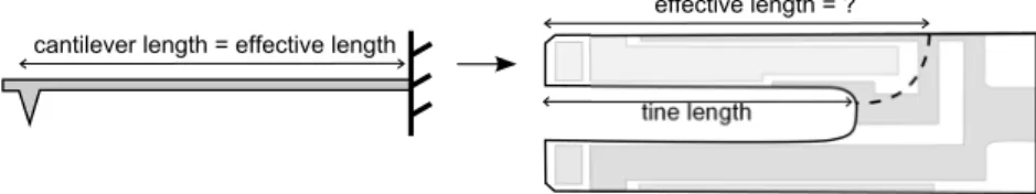
though, QTFs do not simply lend themselves to the application of a classical fixed beam model, due to the presence of two prongs, the role of the electrodes, and the uncertainty as to what would constitute the effective length of the prong (Fig. 3). One model has been developed which hypothesises an elastic coupling between the tines of the standard 32.768 kHz QTF35—however, another study did not find the coupled model to be applicable to QTF models at different eigenfrequencies, nor did it encounter evidence of coupling, therefore opting for a formula based on both geometry and eigenfrequency measurements.20 Yet another
proposed method is based on FEM simulations,34 arguing
that the electrode pattern that governs the oscillating motion precludes a purely mechanical model. Different theoretical methods have also been proposed for the qPlus configuration, such as models based on the continuum theory of elasticity.36 The controversy underlines the need to experimentally validate any adopted model when applying it to a new quartz component.
The force sensitivity of a QTF probe is derived from the noise in its measurement. Amongst the contributing sources, deflection noise is not affected by stiffness k, but other noise sources increase with√kand k and decrease with the quality factor Q.25The choice of the QTF model on which to base a
probe is thus made with regard to the application it is destined for. High stiffness is desirable to avoid jump-to-contact effects, but low stiffness yields better sensitivity: therefore the thinner and smaller tuning forks are chosen when higher sensitivity is required.
D. QTF probe applications
Force sensing with QTF probes is the basis of both imaging (AFM) and quantitative mechanical measurements. Both rely on phase modulation (PM) or frequency modulation
(FM) of the current flowing through the QTF: the force affecting the tip is measured as a shift in the phase or frequency of the oscillation. Because they may sense attractive as well as repulsive van der Waals forces, these modes are sometimes called “non-contact” or “near-contact” AFM. Furthermore, a distinction between conservative and dissipative forces can to a certain extent be extracted in PM- or FM- imaging.37Another
mode of operation which is not conductive to quantitative force sensing but in which imaging can also be carried out is amplitude modulation (AM-AFM, called “intermittent contact” or “tapping mode”). The mode of operation in QTF imaging is roughly subjected to the same choice as in cantilever-based AFM. In liquid or difficult environments, AM-AFM is easier to operate38 but is more damaging to
the tip and sample. On the other hand, high-Q or vacuum environments are especially beneficial to the PM- or FM-AFM modes. These modes can nonetheless be effective in low-Q environments, as shown by the efforts to improve their performance in liquids with PM-AFM39 or in shear-force imaging.40
QTF probes can sense forces down to the pico-Newton range, and resolutions down to 30 pN were reported41 as
early as 1999. Fundamental limits to force detection are linked to the environment, the sensitivity of the probe, its oscillation control, and electronic noise,42 and the potential
imaging resolution of a QTF AFM system correlates with its resolution as a force sensor. Thus has the qPlus sensor famously reached atomic resolutions both in a vacuum43and
in ambient conditions.44 Taking advantage of the laserless
QTF setup, micro-robotic applications in combined use with electronic microscopy have covered the mechanical characterisation of nano-objects,45 stiffness measurements on MEMS resonators,24 and force-sensitive manipulation of CNTs.46 Uses in micro-manipulation have also extended to ambient environments and the exfoliation of two-dimensional objects.47
QTF probes have in addition been involved in various physical and biological observations. Meniscus effects, or water bridges, are a ubiquitous phenomenon in ambient micro-applications: the studies of their viscoelasticity18and rupture
dynamics48have been enabled, thanks to the high stiffness of
QTF probes overcoming jump-to-surface effects. In ambient or nitrogen environments, observations have been made on biological objects, such as bacteria, cells, and biomolecules,17
and the mechanical forces inherent in biological processes like the withdrawal of BSA proteins.49 High sensitivity to sub-nano-Newton forces also makes QTF probes likely candidates for the investigation of such phenomena as the Casimir force.50
FIG. 3. Disparity between cantilevers and QTFs with regard to the mechanical model of a fixed beam: there is no actual delimitation of length for each quartz tine (or prong).
071502-4 Abrahamians, Pham Van, and Régnier Rev. Sci. Instrum. 87, 071502 (2016)
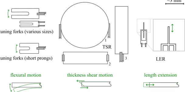
FIG. 4. Types of quartz resonators in electronic components and their modes of oscillation: tuning forks, thickness shear resonators (TSRs), and length extensional resonators (LERs).
III. QUARTZ PROBES AT HIGHER FREQUENCIES
Although the standard 32.768 kHz QTF is the most prominent in the literature, higher frequency quartz probes are desired in order to increase response time and scanning speed51
while retaining the advantage of self-sensing. This section deals with commonly available options for adaptable quartz resonators operating at higher frequencies. These options are divided between tuning forks, thickness shear resonators (TSRs), and length extensional resonators (LERs) (Fig.4). The experimental measurements and FM-AFM results presented later in this section (Tables I and II and Fig. 7) were all obtained in an ambient environment, on a setup consisting of a high frequency lock-in amplifier and phase-locked loop (Zurich Instruments Ltd., HF2LI) and custom-made pre-amplifier52for quartz oscillation control, with a Nanonis SPM
Contoller (SPECS Zurich GmbH, RC4 and SC4) and a Nano-PQD375HS (Mad City Labs, Inc.) closed-loop, 3 degrees-of-freedom nanopositioning system.
A. Tuning forks
Quartz tuning forks exist in the range up to 200 kHz in the fundamental mode, their resonance frequency being limited by the optimization of their geometric parameters
TABLE I. Quality factor (rounded) of the fundamental and overtone reso-nance measured for several models of QTFs.
TF Model Overtone freq (Hz) Q (fund.) Q (overtone)
CFS206 189 505 50 400 860
AB38T 189 505 74 500 760
XT32K 191 263 80 300 2 100
MS1V-T1K 198 120 64 300 70 700 MS1V-T1K with tipa 197 685 4 200 9 200
aMeasurement with tip in ambient air. All other measurements are taken in the original
vacuum-sealed container of the QTF.
and the dimensions that can be attained through the corre-sponding industrial fabrication techniques.7Most QTFs with
eigenfrequencies above 65 kHz are unfortunately designed at a comparable scale for width and thickness but with correspondingly shorter prongs, which results in upwards of 4-6 times higher stiffness.20 Moreover, testing conducted on
certain models (for instance 153 kHz ECS XC978) shows that, while the components all perform well in the vacuum-sealed containers for which they are designed, their fundamental resonances in air may be subjected to a phase shift suggestive of inharmonic perturbations, and accompanied by radically increased noise.
This is not the case with all shorter-pronged types. One 100 kHz model (Citizen CFV206) displayed a −3 dB bandwidth of 0.7 Hz in a vacuum and 7 Hz in air, which is proportionally comparable to the performance of most 32 kHz models. However, FM-AFM imaging with this specific 100 kHz model revealed no favorable changes over its 32 kHz counterparts: maintaining a stable phase lock with the 100 kHz probes required either reduced PLL bandwidth or greatly increased drive amplitude. In addition to the reduced sensitivity from significantly worse signal-to-noise, no improvements in scanning speed were obtained. Probes based on those shorter 100 kHz QTFs may be better suited for AM-AFM.53
TABLE II. Comparison between the FM-AFM scanning speeds attained with probes based on different quartz resonators, for visually comparable image results. Frequency and Q measurements in ambient air, with mounted tip.
Quartz Frequency Q Scanning speed (µm/s) CFS206 32.32 kHz 2 400 1.6 CFV206 97.79 kHz 9 200 <1 XT32K 3.578 MHz 18 800 12
071502-5 Abrahamians, Pham Van, and Régnier Rev. Sci. Instrum. 87, 071502 (2016) Another option towards increasing frequency is overtone
excitation. The first inharmonic overtone for tuning forks corresponds to about 6 times the fundamental frequency, which is around 190 kHz for 32 kHz QTFs. Despite findings in the literature on cantilevers54indicating that overtones must have considerably higher quality factors than their funda-mental modes, most commercial models are designed and optimized for fundamental mode excitation, and their overtone modes therefore tend to have low quality factors (Table I). Here, in one notable exception (Micro Crystal MS1V-T1K), the overtone mode displayed a quality factor matching that of the fundamental mode, and this Q factor remained relatively high in air and with a mounted tip. However, subsequent attempts at exploiting the overtone excitation failed due to exceedingly poor signal-to-noise. This underwhelming performance is in accordance with the results of works on similar components.32 This drawback aside, a study on the potential improvements of overtone excitation with the qPlus scheme has further emphasized the effects of tip length and suggested its use to tune the properties of the probe.55
B. Thickness shear resonators (TSRs)
Thickness shear resonators are AT-cut crystals deformed by shear stress between the two electrodes, so that the faces of the resonator shift in opposite directions (Fig.4), with the deformation being concentrated at the center of the electrodes. They are found in the MHz range and are also packaged in sealed canisters. Provided that their oscillation profile is known, they can be adapted with a tip and used in a way similar to QTFs. They have better thermal stability than QTFs, and their equally high Q factors are not significantly diminished in the air. Since these are single crystals, the addition of glue and a tip does not require balancing; the increased load also has an overall lesser impact on their Q factor, though this impact
increases the closer the added mass is placed to the center of the electrodes.
Three main types of TSRs have been identified from commercially available electronic components (Fig.5): type 1 (“disk-shaped,” or its variant rounded square shapes), type 2 (“horizontal mount”), and type 3 (“contoured beam”). These resonators have been used as temperature and liquid pressure sensors56and type 3 has been introduced as an AFM
sensor,57but they have otherwise been little exploited in
micro-applications compared to the more sensitive QTF. Type 1, due to its much greater mass and stiffness, is not sensitive enough to be the best probe candidate for micro-applications. Type 2, based on FEM analysis and the nature of thickness shear oscillation profiles, is found to be suitable only for lateral (or friction sensing) AFM, as the disposition of the pins on each side leaves no room for a tip to be set and oriented in the direction of its oscillation.
Frequency domain FEM simulations were conducted on TSR type 3, with geometrical dimensions close to those of a real 3.58 MHz resonator (Citizen CA206), yielding an oscillation profile corresponding to a resonant frequency of 3.8 MHz (Fig. 6). The 5% difference with the actual eigenfrequency of the component is interpreted as a result of the dimensions and contoured curvature of both quartz and electrodes being approximated.
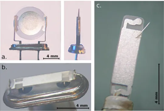
An electrochemically etched Pt/Ir tip with end radius under 100 nm was attached to the resonator (Fig. 5) using silver epoxy, with its placement being a compromise between orienting the tip in the direction of the oscillation and locating it along the displacement profile. Probes thus constituted were not found to be repeatably sensitive to attractive forces in an ambient environment. FM-AFM imaging was hence conducted in the repulsive mode. Images were taken on a calibration grating at various scanning speeds and compared with images of visually similar quality obtained in air on the
FIG. 5. Thickness shear resonators type 1 (a), type 2 (b), and type 3 with mounted tip (c).
071502-6 Abrahamians, Pham Van, and Régnier Rev. Sci. Instrum. 87, 071502 (2016)
FIG. 6. FEM simulation of a 3.58 MHz quartz (type 3) with the COMSOL software: (a) finite element meshing, quadrangular swept; (b) illustration of the thickness shear displacement at the resonance: the upper and lower surfaces of the quartz move in opposite directions; (c) electric displacement field plot, with the greatest amplitude of vibration obtained at a frequency close to that of the component from which the dimensions were taken.
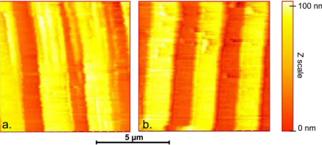
FIG. 7. Ambient FM-AFM images on a calibration grating of 3 µm pitch and 100 nm ridge height; (a) with a 32.768 kHz based probe at a scanning speed of 1.6 µm/s (probe with tip: eigenfrequency 32.321 kHz, Q= 3200, used with a relative frequency shift set point of 0.1 Hz); (b) with a 3.58 MHz based probe at a scanning speed of 12 µm/s (probe with tip: eigenfrequency 3.579 MHz, Q= 18 900, used with a set point of 0.15 Hz).
FIG. 8. Length extensional resonator.61Tips are added to the rightmost end. Reproduced with permission from Appl. Phys. Lett. 87, 13 (2005). Copyright 2005 AIP Publishing LLC.
same sample and setup with a 32 kHz QTF probe (Fig.7). The results obtained at a 7 times faster scanning speed show that the 3.58 MHz quartz based probe, while less sensitive, can prove useful for faster scanning applications (TableII).
C. Length extensional resonators (LERs)
Length extensional resonators (Fig. 8) are more often found as SMD components. These consist in a symmetrically
held oscillating rod (Fig.4) which is elongated in the direction of its length, and at the end of which a tip can be placed. LER-based probes have been used at 1 MHz for atomic resolution imaging58,59 and on soft materials in ambient and liquid
environments.60 Giessibl et al.25 have thoroughly described
these LER probes or “needle sensors” and compared them to qPlus probes for high resolution applications, showing that the needle sensor, with a 600 times greater stiffness than the qPlus (1 080 000 to 1800 N/m), presents 16 times lesser deflection sensitivity (45 µC/m to 2.8 µC/m). The comparison finds the qPlus sensor to have superior signal-to-noise thanks to its geometry and stress profile, while noting that the longitudinal shape of the LER sensor is favourable to reduced microscope dimensions.
IV. CONCLUSION
Probes based on QTFs have been applied throughout the literature in all types of environments, to imaging experiments as well as force sensing characterisation. Along with the systemic possibilities conferred by self-sensing probes, the ease of access to their basic components and the flexibility of
071502-7 Abrahamians, Pham Van, and Régnier Rev. Sci. Instrum. 87, 071502 (2016) TABLE III. Main advantages, drawbacks, and typical frequency ranges of the various types of quartz resonators
and configurations mentioned in this paper. Frequencies are fundamental, except for the explicitly overtone mode QTF. Other frequencies may be commercially available, especially in SMD mounts or overtone modes. Quartz resonator Frequency range Main characteristics
QTF 10–200 kHz Limited frequency, Q factor dependent on balancing QTF, qPlus . . . Halved stiffness, reduced Q factor
QTF, short prongs 65–200 kHz Greater stiffness, reduced sensitivity
QTF, overtone ×6 (>190 kHz) Low Q factor for most models, or low signal-to-noise TSR 3–20 MHz Higher stiffness, greater size, reduced sensitivity LER 0.5–2 MHz Higher stiffness, smaller size, less sensitive than qPlus
their custom assembly makes them tools to rival cantilevers in a wide range of micro-robotic applications, although the availability of miniaturized quartz components is not comparable to that of cantilevers. Beyond the performance of standard QTFs and in keeping with the aforementioned advantages, the design of these probes can yet be adapted to other quartz resonators. TableIIIsummarises the broad aspects of these various types of quartz resonators for force-sensing probes.
The choice of the quartz resonator on which to base a probe is then subjected to a compromise between on one hand sensitivity and, on the other hand, stiffness and resonant frequency. Without reduced dimensions, the higher stiffness that comes together with higher resonant frequency may be considered an advantage in micro-applications when jump-to-contact proximity effects are to be avoided, but only insofar as the resonator still provides the required sensitivity. It is here manifest that many of the currently available MHz-range resonators come with increased dimensions and stiffness, but imaging results with thickness shear resonators have shown that they can still be exploited towards higher-speed operations in lower-sensitivity applications. Finally, although they are not available in as wide a diversity of models as the most common components at this time, length-extensional resonators may be more advantageous in terms of improving speed while retaining a potential for high sensitivity and resolution.
1N. Chaillet and S. Régnier, Microrobotics for Micromanipulation (Wiley-ISTE, 2010).
2K. Karrai and R. D. Grober,Appl. Phys. Lett.66, 1842 (1995).
3M. G. Ruppert and S. O. R. Moheimani,Rev. Sci. Instrum.84, 125006 (2013).
4J. Melcher, J. Stirling, F. G. Cervantes, J. R. Pratt, and G. A. Shaw,Appl.
Phys. Lett.105, 233109 (2014).
5L. Buchaillot, E. Mairiaux, B. Walter, Z. Xiong, M. Faucher, B. Legrand, D. Theron, and E. Algre, in IEEE International on Frequency Control Symposium (FCS)(IEEE, 2014), pp. 1–2.
6M. Gil, T. Manzaneque, J. Hernando-Garcia, A. Ababneh, H. Seidel, and J. Sanchez-Rojas, in 16th International Conference on Solid-State Sensors, Actuators and Microsystems (TRANSDUCERS)(IEEE, 2011), pp. 1496–1499.
7H. T. Wei, C. Y. Hsu, and S. J. Chen, in 9th International Conference on Microsystems, Packaging, Assembly and Circuits Technology (IMPACT) (IEEE, 2014), pp. 494–497.
8M. Barbic, L. Eliason, and J. Ranshaw,Sens. Actuators, A136, 564 (2007). 9X. Su, C. Dai, J. Zhang, and S. J. O’Shea,Biosens. Bioelectron.17, 111
(2002).
10K. Karrai, “Lecture notes on shear and friction force detection with quartz tuning forks,” in presented at the “Ecole Thématique du CNRS” on near-field optics, La Londe les Maures, France, March 2000.
11J.-M. Friedt and E. Carry,Am. J. Phys.75, 415 (2007).
12Y. Seo, P. Cadden-Zimansky, and V. Chandrasekhar,Appl. Phys. Lett.87, 103103 (2005).
13F. Nihei, K. Ideura, H. Kobayashi, J. Taniguchi, and M. Suzuki,J. Low Temp.
Phys.162, 559 (2010).
14J. K. Sell, A. O. Niedermayer, and B. Jakoby,Proc. Eng. Eurosens. XXV 25, 1297 (2011).
15J. Toledo, T. Manzaneque, J. Hernando-García, J. Vázquez, A. Ababneh, H. Seidel, M. Lapuerta, and J. L. Sánchez-Rojas,Microsyst. Technol.20, 945 (2014).
16J. Jahng, M. Lee, H. Noh, Y. Seo, and W. Jhe,Appl. Phys. Lett.91, 023103 (2007).
17J. Otero, L. Gonzalez, and M. Puig-Vidal,Sensors12, 4803 (2012). 18S. An, K. Lee, B. Kim, J. Kim, S. Kwon, Q. Kim, M. Lee, and W. Jhe,Curr.
Appl. Phys.13, 1899 (2013).
19P. Peng, L. Hao, N. Ding, W. Jiao, Q. Wang, J. Zhang, and R. Wang,Rev.
Sci. Instrum.86, 116105 (2015).
20J. Kim, D. Won, B. Sung, S. An, and W. Jhe,Ultramicroscopy141, 56 (2014).
21A. Castellanos-Gomez, N. Agraït, and G. Rubio-Bollinger,Ultramicroscopy 111, 186 (2011).
22H. Labidi, M. Kupsta, T. Huff, M. Salomons, D. Vick, M. Taucer, J. Pitters, and R. A. Wolkow,Ultramicroscopy158, 33 (2015).
23L. Wang, M. Lu, T. Guo, S. Gao, and H. Zhang,Proc. SPIE8916, 89160W (2013).
24J.-O. Abrahamians, B. Sauvet, J. Polesel-Maris, R. Braive, and S. Régnier,
IEEE Trans. Rob.30, 119 (2014).
25F. J. Giessibl, F. Pielmeier, T. Eguchi, T. An, and Y. Hasegawa,Phys. Rev.
B84, 125409 (2011).
26J. A. M. Meza, J. Polesel-Maris, C. Lubin, F. Thoyer, A. Makky, A. Ouerghi, and J. Cousty,Curr. Appl. Phys.15, 1015 (2015).
27D. van Vörden, M. Lange, M. Schmuck, N. Schmidt, and R. Möller,Beilstein
J. Nanotechnol.3, 809 (2012).
28J. M. Merlo-Ramírez, A. Flores-Rosas, D. Antonio-Torres, J. A. Reyes-Avendaño, and S. Mendoza-Vazquez, Rev. Mex. Fis. 60, 142 (2014). 29P. Mühlschlegel, J. Toquant, D. W. Pohl, and B. Hecht,Rev. Sci. Instrum.
77, 016105 (2006).
30L. Botaya, J. Otero, L. González, X. Coromina, G. Gomila, and M. Puig-Vidal,Sens. Actuators, A232, 259 (2015).
31Y. Qin and R. Reifenberger,Rev. Sci. Instrum.78, 063704 (2007). 32B. Babic, M. T. L. Hsu, M. B. Gray, M. Lu, and J. Herrmann,Sens. Actuators,
A223, 167 (2015).
33F. Gao and X. Li,Sensors15, 24530 (2015).
34L. Gonzalez, R. Oria, L. Botaya, M. Puig-Vidal, and J. Otero,
Nanotechnol-ogy26, 055501 (2015).
35A. Castellanos-Gomez, N. Agrait, and G. Rubio-Bollinger,Nanotechnology 20, 215502 (2010).
36J. Berger, M. Švec, M. Müller, M. Ledinský, A. Fejfar, P. Jelínek, and Z. Majzik,Beilstein J. Nanotechnol.4, 1 (2013).
37J. E. Sader, T. Uchihashi, M. J. Higgins, A. Farrell, Y. Nakayama, and S. P. Jarvis,Nanotechnology16, S94 (2005).
38N. B. Matsko, J. Wagner, A. Efimov, I. Haynl, S. Mitsche, W. Czapek, B. Matsko, W. Grogger, and F. Hofer,J. Mod. Phys.2(2), 72–78 (2011). 39L. Pham Van, V. Kyrylyuk, F. Thoyer, and J. Cousty,J. Appl. Phys.104,
074303 (2008).
40L. Gonzalez, D. Martínez-Martín, J. Otero, P. J. de Pablo, M. Puig-Vidal, and J. Gómez-Herrero,Sensors15, 1601 (2015).
41W. H. J. Rensen, N. F. v. Hulst, A. G. T. Ruiter, and P. E. West,Appl. Phys.
Lett.75, 1640 (1999).
071502-8 Abrahamians, Pham Van, and Régnier Rev. Sci. Instrum. 87, 071502 (2016) 42R. D. Grober, J. Acimovic, J. Schuck, D. Hessman, P. J. Kindlemann, J.
Hespanha, A. S. Morse, K. Karrai, I. Tiemann, and S. Manus,Rev. Sci. Instrum.71, 2776 (2000).
43F. J. Giessibl,Appl. Phys. Lett.76, 1470 (2000).
44D. S. Wastl, A. J. Weymouth, and F. J. Giessibl,Phys. Rev. B87, 245415 (2013).
45J. C. Acosta, G. Hwang, J. Polesel-Maris, and S. Régnier,Rev. Sci. Instrum. 82, 035116 (2011).
46V. T. A. Oiko, B. V. C. Martins, P. C. Silva, V. Rodrigues, and D. Ugarte,
Rev. Sci. Instrum.85, 035003 (2014).
47J. O. Island, G. A. Steele, H. S. J. c. der Zant, and A. Castellanos-Gomez, Sci. Lett. J. 4, 163 (2015), available athttp://www.cognizure. com/scilett.aspx?p=200638633; e-print arXiv:1501.06437[cond-mat] (2005).
48W. Bak, B. Sung, J. Kim, S. Kwon, B. Kim, and W. Jhe,Appl. Phys. Lett. 106, 013102 (2015).
49J. Polesel-Maris, J. Legrand, T. Berthelot, A. Garcia, P. Viel, A. Makky, and S. Palacin,Sens. Actuators, B161, 775 (2012).
50T. Ludwig,J. Phys. A: Math. Theor.41, 164025 (2008).
51B. P. Brown, L. Picco, M. J. Miles, and C. F. J. Faul,Small9, 3201 (2013).
52J. Polesel-Maris, “Electronic control and amplification device for a local piezoelectric force measurement probe under a particle beam,” U.S. patent US8627511 B2 (27 January, 2011).
53P. Hsia, “Contrôle de l’orientation de molécules pour la réalisation de nanosources de lumiére,” Ph.D. thesis, École doctorale Ondes et Matière (Orsay, Essonne), France, 2015.
54S. Dohn, R. K. Sandberg, W. E. Svendsen, and A. Boisen,Appl. Phys. Lett. 86, 233501 (2005).
55R. C. Tung, T. Wutscher, D. Martinez-Martin, R. G. Reifenberger, F. Giessibl, and A. Raman,J. Appl. Phys.107, 104508 (2010).
56E. P. EerNisse and R. Wiggins,IEEE Sens. J.1, 79 (2001).
57J. C. Acosta, J. Polesel-Maris, F. Thoyer, H. Xie, S. Haliyo, and S. Régnier,
Nanotechnology24, 065502 (2013).
58T. An, T. Nishio, T. Eguchi, M. Ono, A. Nomura, K. Akiyama, and Y. Hasegawa,Rev. Sci. Instrum.79, 033703 (2008).
59S. Torbrügge, O. Schaff, and J. Rychen,J. Vac. Sci. Technol., B28, C4E12 (2010).
60J. P. Froning, D. Xia, S. Zhang, E. Lægsgaard, F. Besenbacher, and M. Dong,
J. Vac. Sci. Technol., B33, 021801 (2015).
61T. An, T. Eguchi, K. Akiyama, and Y. Hasegawa,Appl. Phys. Lett.87, 133114 (2005).