HAL Id: hal-02499473
https://hal-amu.archives-ouvertes.fr/hal-02499473
Submitted on 5 Mar 2020
HAL is a multi-disciplinary open access archive for the deposit and dissemination of sci-entific research documents, whether they are pub-lished or not. The documents may come from teaching and research institutions in France or
L’archive ouverte pluridisciplinaire HAL, est destinée au dépôt et à la diffusion de documents scientifiques de niveau recherche, publiés ou non, émanant des établissements d’enseignement et de recherche français ou étrangers, des laboratoires
Enhancing the corrosion resistance of Cu/Ni-P/Au
electrical contacts by electropolymerized poly(methyl
methacrylate)
A. Bahramian, Marielle Eyraud, Sébastien Maria, F. Vacandio, T. Djenizian, P. Knauth
To cite this version:
A. Bahramian, Marielle Eyraud, Sébastien Maria, F. Vacandio, T. Djenizian, et al.. Enhancing the corrosion resistance of Cu/Ni-P/Au electrical contacts by electropolymerized poly(methyl methacry-late). Corrosion Science, Elsevier, 2019, 149, pp.75-86. �10.1016/j.corsci.2018.12.026�. �hal-02499473�
Enhancing the corrosion resistance of Cu/Ni-P/Au electrical contacts by
1
electropolymerized poly(methyl methacrylate)
2
A. Bahramiana, M. Eyrauda*, S. Mariab, F. Vacandioa, T. Djenizianc, P. Knautha
3
a Aix Marseille Univ, CNRS, Madirel, UMR 7246, Electrochemistry of Materials Group, Campus St Jérôme, 13397
4
Marseille, France
5
b Aix Marseille Univ, CNRS, Institut de Chimie Radicalaire, UMR 7273, Campus St Jérôme, 13397 Marseille, France
6
c Mines Saint-Etienne, Center of Microelectronics in Provence, Department of Flexible Electronics, 13541 Gardanne,
7
France
8
* Corresponding author: marielle.eyraud@univ-amu.fr
9
Highlights
10
Modifying electrical contacts by electropolymerization of MMA is studied.
11
Ten times increase in the corrosion resistance of electrical contacts is observed.
12
The electrical resistance increased, but remained well below the accepted limit.
13
Cathodic electrodeposition of PMMA effectively sealed the pores of Au top-layer.
14 15
Abstract
16
Cu/Ni-P/Au multi-layer systems are employed as electrical contacts. The Au top-layer is thin and
17
porous. These pores deliver the corrosive media to the under-layer, which induces the corrosion
18
by a galvanic coupling mechanism. Therefore, filling these pores is essential to improve the
19
lifetime of electronic devices. The pores can be sealed by the electrodeposition of poly(methyl
20
methacrylate) that decreased the porosity index (about 97%) and increased the corrosion resistance
21
(about 10 times) of electrical contacts after 10 cycles of electropolymerization. A non-uniform
22
polymeric film, however, was formed at higher number of polymerization cycles (> 50) that
23
decreased the corrosion resistance.
24
Keywords: Corrosion, Cathodic electropolymerization, Electrical contacts, Multi-layer thin films, PMMA, Pores
25 26
1. Introduction
27
Electrical contacts allow exchanging information between a reader and an embedded
28
chip. They are extensively applicable in relays, contactors, switches, and circuit
29
breakers [1,2]. An electrical contact usually consists of a multilayer Cu/Ni/Au thin
30
film stacked to an epoxy tape. Cu is used due to its high electrical conductivity but
31
this metal highly suffers from a poor corrosion resistance and oxidation resistance
32
that increase its resistivity. Au acts as a protective layer against corrosion. However,
33
Cu rapidly diffuses through Au and thus even a thick layer of Au cannot protect it.
P changes the crystalline structure of Ni deposits to an amorphous state. Therefore,
1
Ni-P films have superior properties due to the lack of crystalline defects (such as
2
grain boundaries) that serve as preferential sites for diffusion of chemical species
3
and localized reactions like corrosion. The required thickness of Au is reported to be
4
drastically reduced when amorphous Ni-P films are used. The Au film is notably
5
thin due to its high cost; the total thickness of the Ni barrier layer and Au film
6
remains below 3 µm [3,4].
7
However, the porosity of thin films increases with decreasing the thickness. Hence,
8
thin top Au films in electrical contacts are to some extent porous [4]. The pores act
9
as channels and deliver corrosive media to the under-layer [2]. The galvanic
10
coupling inside these pores is responsible for the fast corrosion of the Ni barrier layer
11
based on the well-known “small anode surface (Ni) – large cathode surface (Au)”
12
phenomenon. After dissolution of Ni films, the subsequent attack of the Cu substrate
13
occurs [3]. Note that corrosion products are often electrical insulators, they can
14
terminate the functionality of electrical contacts [5]. Therefore, improving the
15
corrosion resistance of electrical contacts extends their lifetime and thus has
16
economic and ecological benefits [6]. It is, however, a huge challenge, since Cu, Ni,
17
and Au have a large difference in their standard potentials and any modification
18
should not increase the electrical resistance above a low acceptable value [2].
19
Self-assembled monolayers (SAMs) have shown promising results in improving the
20
corrosion behavior of metals [7–9]. These organic molecules are adsorbed on the
21
surface and form ordered domains. The interaction between SAMs and the substrate
22
can be more or less intensive, depending if the molecules possess a head group with
23
a strong affinity that anchors the molecule to the substrate. SAMs can then modify
24
the porosity of thin films and thus improve the corrosion resistance [2,6,10]. In the
25
case of the Cu/Ni/Au multilayer system, if these molecules accumulate at the pores
26
of the substrate, they can limit the accessibility of the barrier layer to the corrosive
27
media [11]. Song et al. [6] successfully decreased the porosity index of an Au
top-28
coat using SAMs (AUTRONEXTM Nano 104S). However, the application of SAMs
29
may increase the electrical resistivity [12]; furthermore, it suffers from bad
30
reproducibility and is not cost-effective [13].
31
Employing polymers is a well-known strategy to enhance the corrosion resistance
32
[14–17]. Surface anomalies and irregularities, such as pores or surface roughness,
33
have a different surface energy and thus they can act as polymerization centers
34
[18,19]. It was found that pores have a strong free-energy minimum. The monomer,
therefore, can be adsorbed (partially or completely) inside the pore and polymerize
1
there [20]. As a result, it is theoretically possible to fill the pores of thin Au with
2
polymers. However, most organic coatings suffer from a poor adhesion to their
3
metallic substrate. Poly(methyl methacrylate) or PMMA can be strongly
4
chemisorbed (electrografted) on metals owing to its carbonyl functionality [21,22].
5
PMMA is a transparent colorless polymer with a low molecular weight showing high
6
corrosion and chemical resistance [23]. Interestingly, it is possible to etch PMMA
7
using UV [24–26] for removing polymer grown outside the pores that partially
8
covers the gold surface and thus enhances the electrical resistivity. As a result,
9
PMMA seems to be a potential candidate to improve the corrosion behavior of
10
electrical contacts.
11
Electropolymerization is a simple and economical technique that initiates and
12
terminates the chemical reaction through the transfer of electrons [27]. The cathodic
13
electropolymerization of MMA can then be employed to avoid the oxidation of the
14
metallic electrode during the process [22]. Note that this process has been already
15
used to fill titania nanotubes with PMMA for energy storage applications [28–32].
16
An adequate solvent for electropolymerization should be able to dissolve the
17
monomer and support salt in order to provide sufficient conductivity. In this context,
18
dimethyl sulfoxide (DMSO) is reported to be an excellent solvent for MMA [27].
19
In this study, the effects of cathodic electropolymerization of MMA (methyl
20
methacrylate) from DMSO on the corrosion behavior of Cu/Ni-P/Au electrical
21
contacts is investigated for the first time. Several techniques including Scanning
22
Electron Microscopy (SEM), Grazing Angle X-Ray Diffraction (Grazing XRD),
23
Electrochemical Impedance Spectroscopy (EIS), Cyclic Polarization (CP), and Salt
24
Spray (SS) tests were implemented to characterize Cu/Ni-P/Au electrical contacts
25
before and after modification with PMMA.
26 27
2. Experimental procedure
28
A DMSO based solution containing 0.1 M KNO3 (as supporting electrolyte) and 4
29
vol.% MMA was used to electropolymerize MMA on samples. KNO3 was added to
30
DMSO and the solution then was stirred for 60 minutes. MMA was added to the
31
solution and the stirring continued for another 30 minutes. Highly pure chemicals
32
(provided by Sigma-Aldrich) were used as received.
A potentiostat/galvanostat (BioLogic VP300) was employed to perform all
1
electrochemical tests in a three-electrode setup containing the sample as the working
2
electrode, a Pt plate as the counter electrode, and an Ag/AgCl (KCl saturated)
3
reference electrode. Cyclic voltammetry (CV) was used in a cathodic window (-0.5
4
to -2.0 V) with a scan rate of 20 mV.s-1 to polymerize MMA at room temperature.
5
Different cycle numbers, 5, 10, 15, 25, 50, and 100 cycles, were used to modify Cu/
6
Ni-P/Au electrical contacts provided by our industrial partner. The metallic
7
multilayer systems have a total thickness of about 35 µm and are deposited on an
8
epoxy support. The samples were named after their corresponding cycle number,
9
e.g. C0 represents the unmodified sample and C25 is the sample modified by 25
10
cycles of MMA polymerization. All the samples were washed with distilled water
11
and dried with compressed air after the process.
12
A precision scale (±10-4 g) was used to determine the mass of polymer by subtracting
13
the mass before polymerization from the mass after polymerization. The electrical
14
resistivity of samples was measured by a precise Ohm meter (±1 mΩ) using the
15
classical four-probe measurement.
16
The surface morphology and chemical composition of the samples were investigated
17
by a scanning electron microscope (model Philips XL 30 ESEM) equipped with an
18
Energy Dispersive Spectroscopy (EDS) analyzer. The EDS tests were done at 22
19
keV accelerating voltage. A CARL ZEISS/Ultra 55 scanning electron microscope
20
was employed for the cross-section images. The crystalline structure of the samples
21
was evaluated using a Siemens D5000 diffractometer. Cu Kα radiation (λ = 0.15406
22
nm) generated at 40 kV and 30 mA was used to obtain XRD patterns with 0.04° step
23
size over a 2θ range of 25–70°.
24
The corrosion behavior of the samples was investigated by Electrochemical
25
Impedance Spectroscopy (EIS) and Cyclic Polarization (CP) tests. The samples were
26
immersed in a 3% NaCl solution for 60 minutes. The EIS measurements were carried
27
out at Open Circuit Potential (OCP) from 100 kHz to 10 mHz (frequency range) with
28
10 mV voltage amplitude (peak-to-peak). The obtained EIS data were analyzed
29
using Zview software. The CP experiments were done at a scan rate of 0.5 mV/s
30
from -300 mV (vs. OCP) to 500 mV (vs. reference electrode) as the vertex point and
31
reversed at 0 mV (vs. reference) as the finishing point. All the tests were repeated
32
three times and the results were normalized by the exposed area to the corrosive
33
media.
An Ascott S450 Salt Spray apparatus was employed to do SS tests. The SS tests were
1
carried out in accordance with the B 117 ASTM standard. The surface of the samples
2
was periodically evaluated during the SS test by an optical microscope
3
(ARISTOMET) at 100x magnification. The obtained images were analyzed by
4
ImageJ software.
5 6
3. Results and Discussion
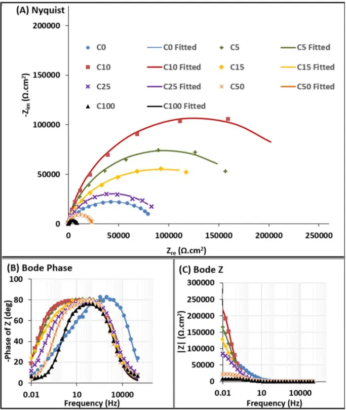
7
Electropolymerization
8
Figure 1 presents the CV curves of MMA electropolymerization on the samples in a
9
potential range between -0.5 to -2.0 V vs. Ag/AgCl. The inlay in that figure
10
corresponds to a smaller potential range (-0.5 to -1.5 V). The first cycle (in blue)
11
clearly presents two reductions waves: the first one between -1.2 to -1.8 V where the
12
reduction current is followed by a plateau, the second one below -1.8 V leading to a
13
steep rise in current.
14
The increase in the number of cycles, till 25 cycles, induces a rapid decrease of the
15
cathodic current in the both regions I and II (see the inlay, for the region I). This
16
decrease is a direct evidence of electropolymerization: the global amount of polymer
17
grafted during each scan is reduced because of the blocking of cathodic sites by the
18
polymer during the previous scans. This result is in good accordance with pervious
19
works [33–35]. Another way to interpret this current decrease is that the amount of
20
polymer at the surface increases during each cycle of polymerization increasing the
21
electrode resistance [33,34]. Interestingly, after 50 cycles a reverse trend was
22
observed: the cathodic current started again to increase and its value after 100 cycles
23
was even slightly higher than after 10 cycles. The formation of a thick mechanically
24
unstable PMMA layer can lead to the detachment from the electrode and thus
25
exposes the metallic surface [33].
26
Baute et al. [22] investigated the cathodic electropolymerization mechanism of some
27
acrylate monomers (including MMA) form dimethylformamide (DMF). CV curves
28
of the investigated acrylic monomers had 2 cathodic peaks. The first peak at less
29
negative potentials was ascribed to the passivation of surface due to the adsorption
30
of reduced monomer. The second peak was attributed to diffusion control. The first
31
peak (around -1.8 V) was considered the critical potential at which the reaction of
32
electrografting happens. Note that the partial electrografting of MMA occurs even
33
before the first peak. This is in agreement with our results where
electropolymerization was carried out from -0.5 to -1.5 V (see inlay in Figure 1) and
1
a similar decrease in current was observed.
2
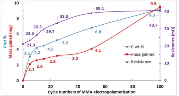
The effect of electropolymerization cycles on the mass gain of samples is illustrated
3
in Figure 2. A strong increase of sample mass can be seen in the first 5 cycles,
4
followed by a slow mass increase between C5 to C50 with a quasi-constant slow rate
5
of deposition. This result is in good accordance with the small variation of the current
6
on CV curves in Figure 1 between C5 to C25. Then a drastic mass increase is
7
observed after 50 cycles. This could be simply due to the higher polymerization
8
amount at higher polymerization cycles or to a non-uniform polymerization.
9 10
Chemical characterizations
11
The EDS technique was employed to assess the amount of C (and thus the polymer
12
amount) as a function of the electropolymerization cycle number (Figure 2). The C
13
content increases rapidly till C5 and then almost linearly between 5 to 100 cycles.
14
The chemical composition of C0 was 3.3 wt.% Cu, 80.6 wt.% Ni, 5.7 wt.% P, and
15
10.4 wt.% Au. The EDS analysis was done at the center of each sample where a
16
uniform distribution of current is expected. Therefore, the inconsistency between the
17
increase of C content and mass gained after 50 cycles could be due to the
non-18
uniform polymerization of MMA especially at the sample edges.
19
No polymer should be formed in the absence of a current flow [33]. To prove that, a
20
sample was immersed in the electrolyte for 4 hours (that is the equivalent time of
21
100 cycles of electropolymerization). No supplementary amount of C was found,
22
showing that PMMA was formed due to the applied potential.
23
To test the solubility of the formed PMMA in relation to the interaction between the
24
polymer and the surface, C10 and C100 were immersed in tetrahydrofuran (THF)
25
for 12 hours. The C amounts were 4.8 and 10.3 % for C10 and C100, respectively,
26
so quite similar to the first analysis (4.2 and 9.2 % respectively). The insolubility of
27
the formed PMMA in THF suggests a strong chemical grafting between Au and the
28
electrodeposited polymer [33].
29
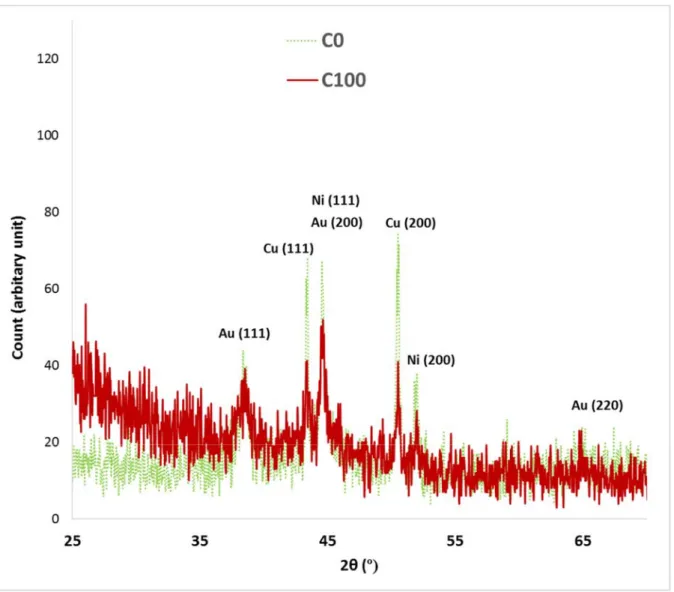
Figure 3 shows the grazing-incidence XRD patterns of C0 and C100. The observed
30
peaks for C0 are related to Au, Ni, and Cu substrate. The strong Cu peak can be
31
justified (200 main orientation) by the low thickness (and the partly amorphous
32
nature) of the Ni-P barrier layer and Au top-coat, and also the porosity of the Au
33
film. The XRD pattern intensity is related to the X-ray penetration depth [36], but
pores can intensify the penetration of X-rays [37]. The C100 pattern was almost
1
similar to C0. However, it showed an increase of the intensity at low diffraction
2
angles and a notable decrease in the intensity of the peaks attributed to Cu and Ni.
3
Note that the intensity for Au is almost intact. The formation of an amorphous phase,
4
here PMMA, on the surface of metals increases the X-ray intensity at low diffraction
5
angles [38–40]. The intensity decrease of Cu and Ni can be attributed to the
PMMA-6 filled pores. 7 8 Morphological characterizations 9
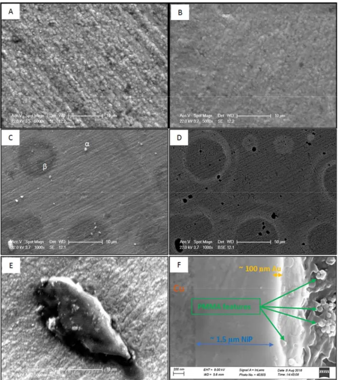
Figure 4 shows optical microscopy images of C0. The micrometer-sized pores are
10
obviously distributed all over the surface. SEM observations of the surface
11
morphology of C0 and C100 are presented in Figure 5 (a and b). Both samples
12
present a similar morphology except that C100 is slightly blurred, possibly due to
13
the presence of a PMMA insulating deposit. At lower magnification, however, C100
14
has two distinct features (noted α and β in Figure 5c).
15
Figure 5c-e shows a uniform formation of polymer on the surface. This
non-16
uniformity of PMMA has been previously reported even at higher concentrations of
17
monomer [33]. The bright objects (marked as α) were found for all PMMA modified
18
samples. The bright objects in SE mode are dark spots in the BSE mode, which is
19
sensitive to the chemical composition (i.e. average atomic number) contrast [41]
20
(Figure 5d). This means they are composed of a material with a low atomic number.
21
Figure 5e shows one of these objects with a low electron beam power (to have a
22
better resolution). Point EDS on this object showed 47.7 wt.% C that proves it is in
23
fact made of PMMA. This object could have been formed in (on) the pores due to
24
the similarities between the black spots in Figure 5d and pores in Figure 4a.
25
The halo shapes (marked as β in Figure 5c) were observed only for C50 and C100.
26
A point EDS analysis showed 16.3 wt.% C (about 7 % higher than the overall C
27
content of C100) that suggests a localized polymerization. All the pores could be
28
filled after a certain number of cycles. The polymerization continues on any
29
available surface since preferential sites (such as pores) are not available, leading to
30
the formation of halo shapes in C50 and C100.
31
The cross-section of C100 is shown in Figure 5f. The polymeric features are obvious
32
on the surface of samples. Therefore, PMMA covered the surface and sealed the
pores. The Au layer with about 100 nm thickness on about 1.5 µm thick Ni-P can be
1
also seen in this figure.
2 3
Electrical resistivity study
4
The electrical resistance of samples as a function of the electropolymerization cycle
5
is depicted in Figure 2. C100 showed a 91% increase in the electrical resistivity.
6
However, its resistance (40.7 mΩ) is still much lower than the resistivity limit of
7
electrical contacts (300 mΩ) [42]. PMMA, therefore, is a potential candidate to
8
enhance the lifetime of electrical contacts. Moreover, Figure 2 supports the presence
9
of a non-uniform polymer layer because a strong resistivity increase should be
10
observed in the presence of a uniform polymeric film [43–45].
11 12
Corrosion resistance study
13
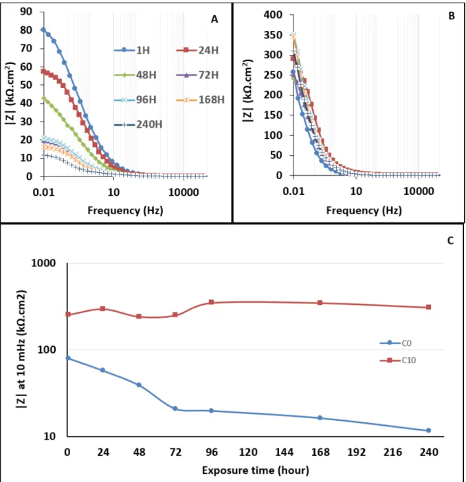
Figure 6 shows the EIS results obtained for samples with (C5-C100) and without
14
(C0) the presence of PMMA. C0 and C5-C100 had asymmetric and symmetric Bode
15
phase curves (Figure 6b), respectively. This suggests that while C0 has two
time-16
constants, the PMMA modified samples present only one-time constant. The value
17
of Z at low frequencies in the Bode modulus plots (Figure 6c) represents the
18
corrosion resistance of samples. The highest corrosion resistance was observed for
19
10 cycles of MMA electropolymerization. This maximum can be also observed in
20
the Nyquist plots, where it corresponds to the maximum diameter of the semi-circles
21
(Figure 6a).
22
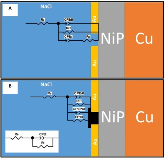
The equivalent circuits are represented in Figure 7. Rs is the solution resistance,
23
which has a constant value of 5-6 Ωcm2 for all experiments. Constant Phase
24
Elements (CPE) are used to represent the non-ideal capacitive behavior of the
25
samples. The CPE impedance is defined as:
26
( 1)
27
is the constant of admittance, i is the imaginary unit, ω (= 2πf) is the angular
28
frequency, and n is the CPE exponent [46]. The n factor is sometimes known as the
29
roughness factor since it is often affected by the surface roughness [47]. The polymer
30
area grows after each cycle of polymerization that should lead to a rougher surface.
31
The values of n can therefore be used to determine the effect of the polymerization
on the surface roughness. Increasing the roughness decreases the value of n (n=1
1
corresponds to an ideal parallel-plate capacitance) in agreement with our
2
experimental data, where n gradually decreased from 0.93 (C0) to 0.83 (C100).
3
In the equivalent circuits, we assume that the initial sample shows pores where
4
corrosion can occur. The fast dissolution of Ni in the pores occurs due to the galvanic
5
coupling between Au (cathode) and Ni (anode). The value of n for CPEp is 0.52
6
suggesting that the corrosion process inside the pores is under mass transport control
7
[48,49]. CPEdl and Rct represent the double layer capacitance and the charge transfer
8
resistance of the electrode, respectively. The CPEdl shows typical values for a
9
metallic electrode (n ≈ 1 and Q in the µF cm-2 range). In the PMMA-modified
10
samples, the pores are filled with the polymer, limiting the corrosion. The proposed
11
equivalent circuits perfectly fitted the experimental data. The fitted values (analyzed
12
by ZVIEW) are summarized in Table 1 and Table 2.
13 14
Assuming that the pores are filled with PMMA after polymerization, the elements
15
representing the pores are substituted with CPEPol and RPol that are related to the
16
capacitance and resistance behavior of the polymer. The equivalent circuit in Figure
17
7b explains the corrosion behavior of the modified samples. This model, however,
18
can be simplified to a Randles model where:
19 ( 2) 20 And 21 ( 3) 22
While the metallic surface area decreases during the polymerization, the polymer
23
surface area increases. Therefore, Rct decreases after each cycle, while RPol increases.
24
Pores are confined spaces and an intensified corrosion process occurs inside them.
25
Filling pores blocks these highly active corrosion sites and thus improves the overall
26
corrosion resistance [50]. Increasing the cycle number of polymerization, however,
27
decreases the uniformity of the surface. Therefore, the corrosion resistance
28
decreases, because a non-uniform protective layer actually promotes the corrosion
29
by leaving a limited exposed area in the corrosive media [51].
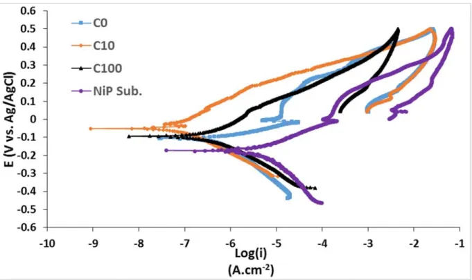
Figure 8 shows the CP curves of C0, C10, C100, and the Ni-P barrier layer. A
1
pseudo-passivation behavior in the anodic branch of the Ni-P barrier was observed,
2
as it was previously reported [52]. C0 showed the same behavior.
3
The Tafel extrapolation method was used to obtain the corrosion current density
4
(icorr), the corrosion potential (Ecorr), and the anodic (βa) and cathodic (βc) slopes from
5
CP tests. These data are used to calculate the polarization resistance (RP) by the
6
Stern-Geary equation [53]. The corresponding data are summarized in Table 3.
7
. ( 4)
8
The comparison of βa for C0 and the Ni-P barrier layer (58 vs. 137 mV.dec-1,
9
respectively) suggests a fast anodic reaction for C0. This anodic reaction could be
10
attributed to the fast dissolution of the Ni-P underlayer due to the galvanic corrosion
11
occurring inside the pores. The passivation behavior was not observed for PMMA
12
modified samples, possibly due to the filled pores.
13
Polarization resistance values were in good agreement with those obtained from EIS
14
tests and C10 revealed the highest resistance value. PMMA-covered samples had a
15
nobler corrosion potential than C0. The more positive corrosion potential can be
16
interpreted as the reduction of the corrosion inclination [54]. Decreasing the porosity
17
shifts the corrosion potential to less cathodic values and decreases the corrosion
18
current density [55]. Therefore, PMMA modified samples should have a lower
19
porosity content. The porosity index (P.I) of surface coatings can be estimated by
20
inserting the corrosion potential difference between the coated sample and the
21
substrate (∆ ), the substrate polarization resistance ( ), the substrate anodic slope
22
( ), and the coating polarization resistance ( ) Eq. 5 [56].
23
. 10 ∆ ( 5)
24
P.I values for C0 and C10 were 0.0269 and 0.0008, respectively, showing a 97%
25
decrease in the porosity of the Au top-layer after 10 cycles of electropolymerization
26
of MMA. A positive hysteresis loop was observed for all samples indicating that the
27
occurrence of localized corrosion is inevitable. Au is generally known to be
28
chemically inert. However, it can be corroded under anodic polarization and in the
29
presence of chloride or bromide ions (due to the formation of Au complexes) [57].
30
Moreover, random pits can be always formed on the surface of metals due to their
31
autocatalytic nature [58]. The corrosion could be even more severe for Au thin films.
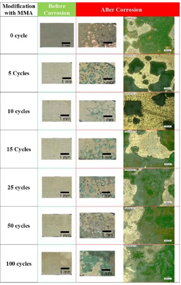
Figure 9 shows the surface of samples after CP tests. The surface of C0 was severely
1
damaged and the Cu substrate can be easily seen. The corrosion on the PMMA
2
modified samples was restricted to the formation of green spots, and C10 had the
3
lowest number of spots. These green corrosion products are reported to be
4
clinoatacamite (Cu2(OH)3Cl) [4]. Therefore, the amount of Cu, Cl, and O after
5
corrosion tests can demonstrate the corrosion progress (Figure 10). According to this
6
figure, C10 presents the lowest content of Cu, O, and Cl and therefore the highest
7
corrosion resistance. The content trends of Cu, Cl, and O (as a function of the
8
polymerization cycle) are in good agreement with the respective polarization
9
resistance and charge transfer resistance values.
10
The salt spray test, which is one of the most employed techniques to determine the
11
atmospheric corrosion behavior of materials, was used to evaluate C0 and C10 in a
12
long-time exposure (10 days) to corrosive media. However, the mass loss (gain) was
13
reported to be negligible for electrical contacts during the salt spray test. As a result,
14
weight measurement is not a suitable technique to estimate the corrosion of electrical
15
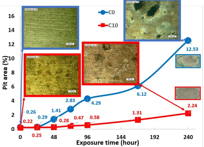
contacts [3]. The pit size was therefore traced and compared for C0 and C10 (Figure
16
11). C0 showed a fast increase in the pit size after 48 hours and large pits were
17
obvious after 240 hours. On the other hand, C10 showed a slow growth of pit area
18
with a surface morphology almost unchanged after 240 hours. However, new pits
19
were formed pointing out that the pitting corrosion is inevitable. EIS was used to
20
verify the long-term corrosion behavior of the samples. As it was mentioned above,
21
the |Z| values at low frequencies (i.e. 10 mHz) can be used to determine the corrosion
22
resistance. Figure 12 shows the Bode Z plots of C0 and C10 during 240 hours of
23
immersion in 3% NaCl. While the corrosion resistance of C0 gradually decreased
24
(from 80 to 12 kΩ.cm2), C10 presented a stable resistance value during 10 days.
25
In conclusion, all corrosion tests, including EIS and salt spray tests, showed that the
26
corrosion resistance of electrical contacts can be significantly improved by
27
depositing PMMA. The best results were obtained using 10 electropolymerization
28
cycles of MMA monomer. The electropolymerization of MMA is a valuable
post-29
treatment method to enhance the corrosion resistance of electrical contacts.
30 31
4. Conclusions
32
The corrosion behavior of Cu/Ni-P/Au electrical contacts can be effectively
33
modified by cathodic electrodeposition of PMMA. A strongly electrografted PMMA
layer. The polymerization preferentially starts at surface defects like pits and pores.
1
Continuing the polymerization when there is no preferential site available leads to a
2
non-uniform growth of PMMA. Therefore, a maximum of corrosion resistance as a
3
function of polymerization cycles is expected (10 cycles in this study). A further
4
increase of the number of polymerization cycles leads to the formation of a
non-5
uniform polymeric film. The sealed pores disconnect the Ni-P barrier layer from the
6
corrosive media and thus improve the corrosion resistance by eliminating the
7
galvanic coupling between the Au top-coat (cathode) and the Ni-P under-layer
8
(anode). The PMMA modified electrical contacts have a high stability against
9
corrosion at high exposure times (10 days). Although PMMA slightly increases the
10
sample resistance, the resistance values are notably lower than the accepted limit for
11
electrical contacts. As a result, electrodeposition of PMMA is an economical
12
solution to improve the lifetime of electrical contacts. Moreover, this technique
13
could be applicable to compensate the negative effects of porosity in other systems
14
as well. The fretting corrosion of electrical contacts, due to the lubricating nature of
15
polymers, may also be improved; this point will be subject of further investigations.
16 17
Acknowledgment
18
The project (APODISE, No. ANR-11-IDEX-0001-02) leading to this publication
19
has received funding from Excellence Initiative of Aix-Marseille University -
20
A*MIDEX, a French “Investissements d'Avenir” programme.
21 22
References
23
[1] M. Uysal, H. Akbulut, M. Tokur, H. Algül, T. Çetinkaya, Structural and sliding wear properties of 24
Ag/Graphene/WC hybrid nanocomposites produced by electroless co-deposition, Journal of Alloys 25
and Compounds. 654 (2016) 185–195. doi:10.1016/j.jallcom.2015.08.264. 26
[2] Z.H. Huang, Y.J. Zhou, W. He, A combination of self-assembled monolayer and hydrophobic 27
conformal coating for anti-corrosion of Cu/NiP/Au 3D circuitry in artificial sweat solution, Surface 28
and Coatings Technology. 320 (2017) 126–131. doi:10.1016/j.surfcoat.2017.01.087. 29
[3] V.K. Murugan, Z. Jia, G.J. Syaranamual, C.L. Gan, Y. Huang, Z. Chen, An investigation into 30
different nickel and nickel–phosphorus stacked thin coatings for the corrosion protection of electrical 31
contacts, Surface and Coatings Technology. 300 (2016) 95–103. doi:10.1016/j.surfcoat.2016.05.013. 32
[4] V.K. Murugan, Z. Jia, G.J. Syaranamual, C.L. Gan, Y. Huang, Z. Chen, Atmospheric corrosion 33
resistance of electroplated Ni/Ni–P/Au electronic contacts, Microelectronics Reliability. 60 (2016) 34
84–92. doi:10.1016/j.microrel.2016.02.014. 35
[5] K. Meyyappan, G. Murtagian, A. Kurella, B. Pathangey, A. McAllister, S. Parupalli, Corrosion 36
Studies on Gold-Plated Electrical Contacts, IEEE Transactions on Device and Materials Reliability. 37
14 (2014) 869–877. doi:10.1109/TDMR.2014.2333758. 38
[6] J. Song, L. Wang, A. Zibart, C. Koch, Corrosion Protection of Electrically Conductive Surfaces, 39
Metals. 2 (2012) 450–477. doi:10.3390/met2040450. 40
[7] T. Shimura, K. Aramaki, Improvement of the film thickness by modification of the 1
hydroxymethylbenzene SAM with tetraethoxysilane and octanediol for protection of iron from 2
corrosion in 0.5M NaCl, Corrosion Science. 50 (2008) 1397–1405. doi:10.1016/j.corsci.2007.12.010. 3
[8] A.-R. El-Sayed, U. Harm, K.-M. Mangold, W. Fürbeth, Protection of galvanized steel from corrosion 4
in NaCl solution by coverage with phytic acid SAM modified with some cations and thiols, 5
Corrosion Science. 55 (2012) 339–350. doi:10.1016/j.corsci.2011.10.036. 6
[9] C. Li, L. Li, C. Wang, Y. Zhu, W. Zhang, Study of the protection performance of self-assembled 7
monolayers on copper with the scanning electrochemical microscope, Corrosion Science. 80 (2014) 8
511–516. doi:10.1016/j.corsci.2013.12.003. 9
[10] S. Nineva, S. Berger, F. Talgner, U. Electroplating, New Post-Treatment Process with Enhanced 10
Technical Performance: Corrosion Protection for Electrical Contacts, (n.d.). 11
[11] D.A. Patel, A.M. Weller, R.B. Chevalier, C.A. Karos, E.C. Landis, Ordering and defects in self-12
assembled monolayers on nanoporous gold, Applied Surface Science. 387 (2016) 503–512. 13
doi:10.1016/j.apsusc.2016.05.149. 14
[12] M. Hakamada, N. Kato, M. Mabuchi, Electrical resistivity of nanoporous gold modified with thiol 15
self-assembled monolayers, Applied Surface Science. 387 (2016) 1088–1092. 16
doi:10.1016/j.apsusc.2016.07.059. 17
[13] D. Capitao, B. Limoges, C. Fave, B. Schöllhorn, On the decisive role of the sulfur-based anchoring 18
group in the electro-assisted formation of self-assembled monolayers on gold, Electrochimica Acta. 19
257 (2017) 165–171. doi:10.1016/j.electacta.2017.09.163. 20
[14] A.M. Fenelon, C.B. Breslin, The electropolymerization of pyrrole at a CuNi electrode: corrosion 21
protection properties, Corrosion Science. 45 (2003) 2837–2850. doi:10.1016/S0010-938X(03)00104-22
5. 23
[15] D. Kowalski, M. Ueda, T. Ohtsuka, The effect of ultrasonic irradiation during electropolymerization 24
of polypyrrole on corrosion prevention of the coated steel, Corrosion Science. 50 (2008) 286–291. 25
doi:10.1016/j.corsci.2007.05.027. 26
[16] Z. Grubač, I.Š. Rončević, M. Metikoš-Huković, Corrosion properties of the Mg alloy coated with 27
polypyrrole films, Corrosion Science. 102 (2016) 310–316. doi:10.1016/j.corsci.2015.10.022. 28
[17] İ. Çakmakcı, B. Duran, M. Duran, G. Bereket, Experimental and theoretical studies on protective 29
properties of poly(pyrrole-co-N-methyl pyrrole) coatings on copper in chloride media, Corrosion 30
Science. 69 (2013) 252–261. doi:10.1016/j.corsci.2012.12.011. 31
[18] A. Baumgärtner, M. Muthukumar, Effects of surface roughness on adsorbed polymers, The Journal 32
of Chemical Physics. 94 (1991) 4062–4070. doi:10.1063/1.460656. 33
[19] J.F. Douglas, How Does Surface Roughness Affect Polymer-Surface Interactions?, Macromolecules. 34
22 (1989) 3707–3716. 35
[20] G.F. Hermsen, N.F.A. van der Vegt, M. Wessling, Monte Carlo Calculations of Polymer Adsorption 36
at the Entrance of Cylindrical Pores in Flat Adsorbing Surfaces, Soft Materials. 1 (2003) 295–312. 37
doi:10.1081/SMTS-120026595. 38
[21] N. Baute, L. Martinot, R. Jérôme, Investigation of the cathodic electropolymerization of acrylonitrile, 39
ethylacrylate and methylmethacrylate by coupled quartz crystal microbalance analysis and cyclic 40
voltammetry, Journal of Electroanalytical Chemistry. 472 (1999) 83–90. 41
[22] S.L. Cram, G.M. Spinks, G.G. Wallace, H.R. Brown, Electrochemical polymerization of acrylics on 42
stainless steel cathodes, Journal of Applied Polymer Science. 87 (2003) 765–773. 43
doi:10.1002/app.11436. 44
[23] G. Lu, Y.-M. Li, C.-H. Lu, Z.-Z. Xu, Corrosion protection of iron surface modified by poly(methyl 45
methacrylate) using surface-initiated atom transfer radical polymerization (SI-ATRP), Colloid and 46
Polymer Science. 288 (2010) 1445–1455. doi:10.1007/s00396-010-2283-x. 47
[24] B. Braren, D. Seeger, Low temperature UV laser etching of PMMA: On the mechanism of ablative 48
photodecomposition (APD), Journal of Polymer Science Part C: Polymer Letters. 24 (1986) 371–376. 49
doi:10.1002/pol.1986.140240802. 50
[25] R.W. Johnstone, I.G. Foulds, M. Parameswaran, Deep-UV exposure of poly(methyl methacrylate) at 1
254 nm using low-pressure mercury vapor lamps, Journal of Vacuum Science & Technology B: 2
Microelectronics and Nanometer Structures. 26 (2008) 682. doi:10.1116/1.2890688. 3
[26] N. Yufa, S. Fronk, S.B. Darling, R. Divan, W. Lopes, S.J. Sibener, Modifying metal–polymer 4
nanostructures using UV exposure, Soft Matter. 5 (2009) 1683. doi:10.1039/b820775e. 5
[27] B.L. Funt, K.C. Yu, Electroinitiated polymerization of methyl methacrylate in a homogeneous 6
medium, Journal of Polymer Science. 62 (1962) 359–367. doi:10.1002/pol.1962.1206217408. 7
[28] G.D. Salian, C. Lebouin, A. Demoulin, M.S. Lepihin, S. Maria, A.K. Galeyeva, A.P. Kurbatov, T. 8
Djenizian, Electrodeposition of polymer electrolyte in nanostructured electrodes for enhanced 9
electrochemical performance of thin-film Li-ion microbatteries, Journal of Power Sources. 340 10
(2017) 242–246. doi:10.1016/j.jpowsour.2016.11.078. 11
[29] N. Plylahan, S. Maria, T.N. Phan, M. Letiche, H. Martinez, C. Courrèges, P. Knauth, T. Djenizian, 12
Enhanced electrochemical performance of Lithium-ion batteries by conformal coating of polymer 13
electrolyte, Nanoscale Research Letters. 9 (2014) 544. doi:10.1186/1556-276X-9-544. 14
[30] N.A. Kyeremateng, F. Dumur, P. Knauth, B. Pecquenard, T. Djenizian, Electrodeposited copolymer 15
electrolyte into nanostructured titania electrodes for 3D Li-ion microbatteries, Comptes Rendus 16
Chimie. 16 (2013) 80–88. doi:10.1016/j.crci.2012.05.002. 17
[31] N. Plylahan, N.A. Kyeremateng, M. Eyraud, F. Dumur, H. Martinez, L. Santinacci, P. Knauth, T. 18
Djenizian, Highly conformal electrodeposition of copolymer electrolytes into titania nanotubes for 19
3D Li-ion batteries, Nanoscale Research Letters. 7 (2012) 349. doi:10.1186/1556-276X-7-349. 20
[32] N.A. Kyeremateng, F. Dumur, P. Knauth, B. Pecquenard, T. Djenizian, Electropolymerization of 21
copolymer electrolyte into titania nanotube electrodes for high-performance 3D microbatteries, 22
Electrochemistry Communications. 13 (2011) 894–897. doi:10.1016/j.elecom.2011.03.026. 23
[33] S. Cram, Mechanism of electropolymerisation of methyl methacrylate and glycidyl acrylate on 24
stainless steel, Electrochimica Acta. 47 (2002) 1935–1948. doi:10.1016/S0013-4686(02)00097-X. 25
[34] M. Braglia, I.V. Ferrari, L. Pasquini, T. Djenizian, M. Sette, M.L. Di Vona, P. Knauth, 26
Electrochemical synthesis of thin, dense, and conformal anion exchange membranes with quaternary 27
ammonium groups, Electrochimica Acta. 265 (2018) 78–88. doi:10.1016/j.electacta.2018.01.151. 28
[35] I.V. Ferrari, M. Braglia, T. Djenizian, P. Knauth, M.L. Di Vona, Electrochemically engineered single 29
Li-ion conducting solid polymer electrolyte on titania nanotubes for microbatteries, Journal of Power 30
Sources. 353 (2017) 95–103. doi:10.1016/j.jpowsour.2017.03.141. 31
[36] G. Sundararajan, L. Rama Krishna, Mechanisms underlying the formation of thick alumina coatings 32
through the MAO coating technology, Surface and Coatings Technology. 167 (2003) 269–277. 33
doi:10.1016/S0257-8972(02)00918-0. 34
[37] J.A. Curran, T.W. Clyne, Porosity in plasma electrolytic oxide coatings, Acta Materialia. 54 (2006) 35
1985–1993. doi:10.1016/j.actamat.2005.12.029. 36
[38] T. Weisemoeller, F. Bertram, S. Gevers, C. Deiter, A. Greuling, J. Wollschläger, Effect of amorphous 37
interface layers on crystalline thin-film x-ray diffraction, Physical Review B. 79 (2009). 38
doi:10.1103/PhysRevB.79.245422. 39
[39] S.E. Fritz, S.M. Martin, C.D. Frisbie, M.D. Ward, M.F. Toney, Structural Characterization of a 40
Pentacene Monolayer on an Amorphous SiO 2 Substrate with Grazing Incidence X-ray Diffraction,
41
Journal of the American Chemical Society. 126 (2004) 4084–4085. doi:10.1021/ja049726b. 42
[40] H. Sirringhaus, P.J. Brown, R.H. Friend, M.M. Nielsen, K. Bechgaard, B.M.W. Langeveld-Voss, 43
A.J.H. Spiering, R.A.J. Janssen, E.W. Meijer, P. Herwig, Two-dimensional charge transport in self-44
organized, high-mobility conjugated polymers, 401 (1999) 4. 45
[41] L. Reimer, Imaging with Secondary and Backscattered Electrons, in: Scanning Electron Microscopy, 46
Springer, Berlin, Heidelberg, 1985: pp. 227–271. doi:10.1007/978-3-662-13562-4_6. 47
[42] J. Song, C. Koch, L. Wang, Correlation between Wear Resistance and Lifetime of Electrical 48
Contacts, Advances in Tribology. 2012 (2012) 1–9. doi:10.1155/2012/893145. 49
[43] B.M. Rumyantsev, S.B. Bibikov, A.V. Bychkova, V.G. Leontiev, V.I. Berendyaev, O.N. Sorokina, 1
A.L. Kovarskii, Electric conductivity of polymer films filled with magnetic nanoparticles, Russian 2
Journal of Physical Chemistry A. 90 (2016) 2426–2433. doi:10.1134/S0036024416120244. 3
[44] H.Q. Zhang, Y. Jin, Y. Qiu, The optical and electrical characteristics of PMMA film prepared by spin 4
coating method, IOP Conference Series: Materials Science and Engineering. 87 (2015) 012032. 5
doi:10.1088/1757-899X/87/1/012032. 6
[45] A.R. Blythe, Electrical resistivity measurements of polymer materials, Polymer Testing. 4 (1984) 7
195–209. doi:10.1016/0142-9418(84)90012-6. 8
[46] R. Farahmand, B. Sohrabi, A. Ghaffarinejad, M.R. Zamani Meymian, Synergistic effect of 9
molybdenum coating and SDS surfactant on corrosion inhibition of mild steel in presence of 3.5% 10
NaCl, Corrosion Science. 136 (2018) 393–401. doi:10.1016/j.corsci.2018.03.030. 11
[47] S.M. Rezaei Niya, M. Hoorfar, On a possible physical origin of the constant phase element, 12
Electrochimica Acta. 188 (2016) 98–102. doi:10.1016/j.electacta.2015.11.142. 13
[48] S.C. Chung, J.R. Cheng, S.D. Chiou, H.C. Shih, EIS behavior of anodized zinc in chloride 14
environments, Corrosion Science. 42 (2000) 1249–1268. doi:10.1016/S0010-938X(99)00129-8. 15
[49] F. Yang, H. Kang, E. Guo, R. Li, Z. Chen, Y. Zeng, T. Wang, The role of nickel in mechanical 16
performance and corrosion behaviour of nickel-aluminium bronze in 3.5 wt.% NaCl solution, 17
Corrosion Science. 139 (2018) 333–345. doi:10.1016/j.corsci.2018.05.012. 18
[50] G. Song, A. Atrens, M. Dargusch, In~uence of microstructure on the corrosion of diecast AZ80D, 19
Corrosion Science. (n.d.) 25. 20
[51] J. Lee, D. Berman, Inhibitor or promoter: Insights on the corrosion evolution in a graphene protected 21
surface, Carbon. 126 (2018) 225–231. doi:10.1016/j.carbon.2017.10.022. 22
[52] A. Bahramian, M. Eyraud, F. Vacandio, P. Knauth, Improving the corrosion properties of amorphous 23
Ni-P thin films using different additives, Surface and Coatings Technology. 345 (2018) 40–52. 24
doi:10.1016/j.surfcoat.2018.03.075. 25
[53] T. Pojtanabuntoeng, B. Kinsella, H. Ehsani, J. McKechnie, Assessment of corrosion control by pH 26
neutralisation in the presence of glycol at low temperature, Corrosion Science. 126 (2017) 94–103. 27
doi:10.1016/j.corsci.2017.06.018. 28
[54] G. Liu, Z. Huang, L. Wang, W. Sun, S. Wang, X. Deng, Effects of Ce4+ on the structure and 29
corrosion resistance of electroless deposited Ni–Cu–P coating, Surface and Coatings Technology. 30
222 (2013) 25–30. doi:10.1016/j.surfcoat.2013.01.053. 31
[55] W. Xu, X. Lu, B. Zhang, C. Liu, S. Lv, S. Yang, X. Qu, Effects of Porosity on Mechanical Properties 32
and Corrosion Resistances of PM-Fabricated Porous Ti-10Mo Alloy, Metals. 8 (2018) 188. 33
doi:10.3390/met8030188. 34
[56] J. Creus, H. Mazille, H. Idrissi, Porosity evaluation of protective coatings onto steel, through 35
electrochemical techniques, Surface and Coatings Technology. 130 (2000) 224–232. 36
doi:10.1016/S0257-8972(99)00659-3. 37
[57] M.D. Vedenyapina, V.V. Kuznetsov, D.I. Rodikova, N.N. Makhova, A.A. Vedenyapin, Anodic 38
corrosion of gold in solutions of diaminoalkanes, Mendeleev Communications. 28 (2018) 181–183. 39
doi:10.1016/j.mencom.2018.03.024. 40
[58] G.S. Frankel, Pitting Corrosion of Metals, Journal of The Electrochemical Society. 145 (1998) 2186. 41
doi:10.1149/1.1838615. 42
Tables
Table 1. Fitted values of C0 using the EC presented in Figure 7a
Rs (Ω.cm2) CPEdl Rct (kΩ.cm2) CPEp Rp (kΩ.cm2) Y° (µF.cm-2.sn-1) n (µF.cmY° -2.sn-1) n 5.1±0.2 2.0±0.5 0.93±0.01 96±5 8.8±0.5 0.52±0.06 6±2
Table 2. Fitted values of PMMA modified samples using the EC presented in Figure 7b
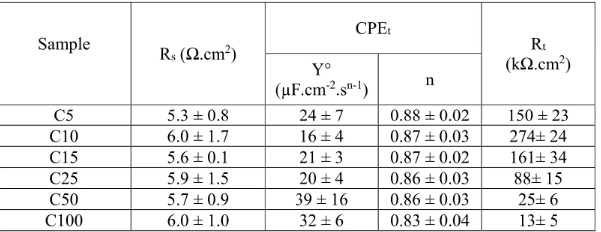
Sample R s (Ω.cm2) CPEt Rt (kΩ.cm2) Y° (µF.cm-2.sn-1) n C5 5.3 ± 0.8 24 ± 7 0.88 ± 0.02 150 ± 23 C10 6.0 ± 1.7 16 ± 4 0.87 ± 0.03 274± 24 C15 5.6 ± 0.1 21 ± 3 0.87 ± 0.02 161± 34 C25 5.9 ± 1.5 20 ± 4 0.86 ± 0.03 88± 15 C50 5.7 ± 0.9 39 ± 16 0.86 ± 0.03 25± 6 C100 6.0 ± 1.0 32 ± 6 0.83 ± 0.04 13± 5
Table 3. Corrosion current density, corrosion potential, anodic and cathodic slopes, and polarization resistance of Ni-P barrier layer and C0-C100
Sample icorr
(µA.cm-2) vs. Ag/AgCl Ecorr (mV)
Average Tafel slope (mV. dec-1)
Rp
(kΩ.cm2)
βa βc
Ni-P barrier layer 6.68 ± 0.78 -202 ± 7 137 ± 10 147 ± 14 5 ± 1
C0 0.50 ± 0.10 -110 ± 7 58 ± 5 196 ± 13 40 ± 8 C5 0.18 ± 0.02 -14 ± 23 149 ± 26 99 ± 5 148 ± 24 C10 0.08 ± 0.01 -36 ± 3 151 ± 9 102 ± 21 339 ± 92 C15 0.15 ± 0.04 4 ± 11 114 ± 39 114 ± 3 168± 28 C25 0.24 ± 0.10 -16 ± 20 128 ± 31 108 ± 4 116 ± 35 C50 1.93 ± 0.73 -33 ± 13 187 ± 40 135 ± 4 20 ± 8 C100 2.68 ± 1.92 -75 ± 13 199 ± 76 158 ± 42 17±8
Figures
Figure 1. CV curves of cathodic electropolymerization of MMA on Cu/Ni-P/Au electrical contacts from 0.1 M KNO3 DMSO solution with a scan rate of 20 mV.s-1.
Figure 3. Grazing incidence XRD patterns of C0 and C100.
Figure 5. (a) SE SEM image of C0, (b) SE SEM image of C100, (c) SE SEM image of C100, (d) BSE SEM image of C100, (e) SE SEM image of C100 (10kV electron beam power), and (f) cross-section BSE SEM image of C100 .
Figure 10. (a) Cu wt.%, and (b) Cl wt.% and O wt.% of samples after the corrosion tests as a function of the electropolymerization cycle number.
Figure 11. Pit area of C0 and C10 during 240 hours of salt spray test.
Figure 12. Bode Z plots of (a) C0 and (b) C10 and (c) their |Z| values at 10 mHz during 240 hours immersion in 3% NaCl solution.