Demountable Toroidal Field Magnets for
Use in a Compact Modular Fusion Reactor
The MIT Faculty has made this article openly available.
Please share
how this access benefits you. Your story matters.
Citation
Mangiarotti, F J, J Goh, M Takayasu, L Bromberg, J V Minervini,
and D Whyte. “Demountable Toroidal Field Magnets for Use in a
Compact Modular Fusion Reactor.” Journal of Physics: Conference
Series 507, no. 3 (May 12, 2014): 032030.
As Published
http://dx.doi.org/10.1088/1742-6596/507/3/032030
Publisher
IOP Publishing
Version
Final published version
Citable link
http://hdl.handle.net/1721.1/117193
Terms of Use
Creative Commons Attribution 3.0 Unported license
Detailed Terms
http://creativecommons.org/licenses/by/3.0/
Journal of Physics: Conference Series
OPEN ACCESS
Demountable Toroidal Field Magnets for Use in a
Compact Modular Fusion Reactor
To cite this article: F J Mangiarotti et al 2014 J. Phys.: Conf. Ser. 507 032030
View the article online for updates and enhancements.
Related content
Lockheed Martin unveils fusion reactor plans
Andy Extance
-ADX: a high field, high power density, advanced divertor and RF tokamak
B. LaBombard, E. Marmar, J. Irby et al.
-Small fusion reactors could deliver big gains, firm says
Michael Banks
-Recent citations
Performance correlation between YBa2Cu3O7 coils and short samples for coil technology development
X Wang et al
-Advances on the Design of Demountable Toroidal Field Coils With REBCO Superconductors for an ARIES-I Class Fusion Reactor
Franco J. Mangiarotti and Joseph V. Minervini
-Effect of the axial stress and the magnetic field on the critical current and the electric resistance of the joints between HTS coated conductors
K Konstantopoulou et al
Demountable Toroidal Field Magnets for Use in a Compact
Modular Fusion Reactor
F. J. Mangiarotti*, J. Goh, M. Takayasu, L. Bromberg, J. V. Minervini and D. Whyte
Plasma Science and Fusion Center, Massachusetts Institute of Technology, Cambridge, MA 02139, USA
*E-mail: fjm@mit.edu
Abstract. A concept of demountable toroidal field magnets for a compact fusion reactor is
discussed. The magnets generate a magnetic field of 9.2 T on axis, in a 3.3 m major radius tokamak. Subcooled YBCO conductors have a critical current density adequate to provide this large magnetic field, while operating at 20 K reduces thermodynamic cooling cost of the resistive electrical joints. Demountable magnets allow for vertical replacement and maintenance of internal components, potentially reducing cost and time of maintenance when compared to traditional sector maintenance. Preliminary measurements of contact resistance of a demountable YBCO electrical joint between are presented.
1. Introduction
The recent development of YBCO superconducting tapes and cabling methods could be a revolutionary development for magnetic fusion. Subcooled YBCO has larger critical current density at high magnetic fields (more than 20 T) than low temperature superconductors (LTS) such as Nb3Sn and
NbTi. Also, YBCO can be operated at higher temperatures than LTS, reducing the thermodynamic cooling cost and allowing resistive loss in the coil joints.
An innovative concept of fusion reactor has been developed in 2012 by the MIT Fusion Reactor Design course, partially inspired by the Vulcan concept design [1]. A comprehensive report of the characteristics of the reactor is expected to be published later this year. The reactor is 3.3 m in major radius and operates in steady state. The magnetic field on axis is 9.2 T. The tritium breeding blanket is entirely made of liquid FLiBe, and the toroidal field (TF) coils are demountable, allowing for vertical replacement of the internal components of the reactor. This maintenance scheme is much faster, easier and cheaper than sector maintenance, and the replaceable parts such as the vacuum vessel can be fabricated off-site with lower tolerances.
We developed a concept of demountable toroidal field coils for a fusion reactor, with preliminary stress and heating simulations. We have designed demountable electrical joints for YBCO stacked tape conductors for the TF coil system, and tested a small scale prototype of the electrical joint.
2. Toroidal field magnets concept and stress analysis
The TF coil system is composed by 18 demountable coils. The shape of the coils is based on the constant tension D-shape. The coil is divided in two parts, as shown in figure 1: a removable upper leg and a stationary lower leg. The legs are joined in the outer midplane, and in the top of the coils. The structure of the coils is made of stainless steel 316LN.
11th European Conference on Applied Superconductivity (EUCAS2013) IOP Publishing Journal of Physics: Conference Series 507 (2014) 032030 doi:10.1088/1742-6596/507/3/032030
Content from this work may be used under the terms of theCreative Commons Attribution 3.0 licence. Any further distribution of this work must maintain attribution to the author(s) and the title of the work, journal citation and DOI.
The forces in the outer joint are supported by bolts. A steel tension ring supports the upper leg on the top joint. The forces in the central column are supported by wedging of the TF coils against each other, and by buckling against the central solenoid. The central solenoid is filled with a fiberglass/epoxy plug to reduce the maximum stresses in this region.
Figure 1. Schematic design of the TF coil system. (Left) assembled; (right) disassembled. The
structure is made of stainless steel 316LN, the cables are YBCO conductors. The central solenoid is filled with a fibreglass/epoxy plug to take the compressive loads on the inside.
A finite element method (FEM) simulation of the Lorentz loads in the TF coils was made to estimate the stresses in the structure. The model is half a single TF coil. The load in the coils is due to the Lorentz force in the conductors due to the toroidal magnetic field generated by all 18 coils. Roller boundaries simulate the rotational symmetry, and the contact between the two legs. The simulation results are shown in figure 2. The maximum stress in the structure is approximately 700 MPa and the yield strength of stainless steel 316LN is larger than 1000 MPa [2], which gives a safety factor of approximately 1.4.
1 GPa
0 GPa 0.5 GPa
Figure 2. Results of FEM simulation of the stresses in the TF coils. (Left) bottom leg; (right) top leg.
The colors represent the von Mises stress. The safety factor is approximately 1.4 in the worst areas. To provide the 9.2 T on axis, a current of 8.4 MA turn is required in each TF coil. The current is carried by 70 kA YBCO cables; each cable composed by 250 YBCO tapes (25 mm width) assembled using the Twisted Stacked Tape Conductor method [3]. The superconductors are cooled with liquid 11th European Conference on Applied Superconductivity (EUCAS2013) IOP Publishing Journal of Physics: Conference Series 507 (2014) 032030 doi:10.1088/1742-6596/507/3/032030
hydrogen at 20 K. The maximum magnetic field the superconductors are exposed to is approximately 25 T, which gives a critical current margin of approximately 50% (extrapolated from single tape measurements at 25 T and 4.2 K [4]). The cable length is 19 m for the bottom leg, and 7.5 m for the top leg, which allows selecting the segments of each YBCO spool with better performance for the cables located in higher magnetic field areas.
A total of 240 joints in series will be required in each TF coil. The concept for electrical joint between superconductors will be discussed in the next section. Because of the nature of the joint, it is undesirable to have relative motions of its elements. Thus, the structure has to be sufficiently stiff to prevent “scuffing”. Some relative motion can be tolerated in the direction of the conductors, but the joint should be designed to prevent having substantial loads perpendicular to them.
3. Demountable YBCO electrical joints concept and preliminary measurements
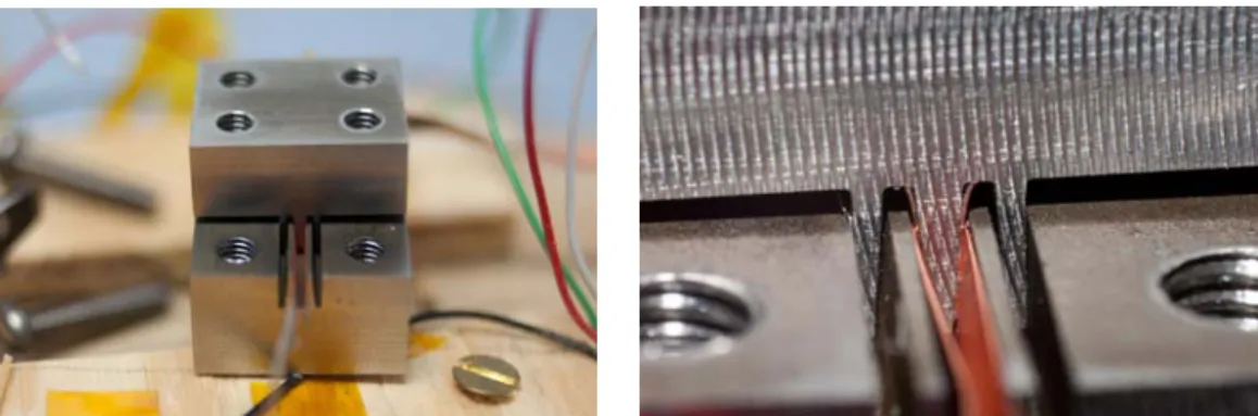
A demountable “comb teeth” type joint geometry has been developed. The conceptual drawing is shown in figure 3. This geometry offers a good balance between contact area and joint space. A small scale prototype of joint structure for 4 mm wide tape was designed and fabricated using EDM process for the intricate details. This prototype allows joining up to four pairs of YBCO tapes. Figure 4 shows the prototype comb teeth joint with two pairs of YBCO tapes.
Figure 3. “comb teeth” joint concept. YBCO tapes sit in “comb teeth” in both structures. When
pressed together, the YBCO tapes form a “lap” joint.
Figure 4. Comb teeth demountable joint device for YBCO tapes. (Left) photograph of a “comb teeth”
type joint fabricated by EDM; (right) close-up photograph of the assembled joint, showing details. Figure 5 shows preliminary results obtained by comb teeth demountable joint devices for a 4-tape device and also a 8-tape device at 77 K. 4 mm SuperPower SCS-4050-AP YBCO tape was used in all measurements. The joint resistances per tape are plotted as a function of the reciprocal of joint length, since the contact resistance is proportional to the reciprocal of the contact surface area. As seen in figure 5 the contact resistances linearly changed with the inverse of joint length; the lowest joint resistance of 25 nΩ was achieved for a 40 mm long joint. The average joint resistance is 30 μΩ·mm2.
As seen in the figure it is noted that the uniformity of contact joint resistances is better for shorter length of joints. In this device the very high contact pressure can be obtained by the wedge effect, therefore the low joint resistance could be obtained. However, it was difficult to adjust the pressure 11th European Conference on Applied Superconductivity (EUCAS2013) IOP Publishing Journal of Physics: Conference Series 507 (2014) 032030 doi:10.1088/1742-6596/507/3/032030
and obtain a uniform pressure for all tapes. More work is required to improve the demountable joint device and to scale up.
Figure 5. Preliminary results obtained by comb teeth type demountable joint device. Joint resistance
plotted as a function of the inverse of joint length. The average contact resistance is 30 μΩ·mm2.
Extrapolating the preliminary results to the TF magnet system described in the previous section, 25 mm wide tape and 10 long joint, a total of 11 kW of heating power is generated in the joints of the entire TF system at the low temperature. To remove that power approximately 800 kW of electricity is required.
To keep the temperature controlled in the joint, each “comb tooth” has a cooling channel in its base, with liquid hydrogen flowing through it. For a 1 mm wide cooling channel in a 2 mm wide comb tooth, with 1 m/s liquid hydrogen flow at 20 K, a 2D FEM simulation showed that the peak temperature is less than 21.3 K in the superconductor.
4. Conclusions
Demountable toroidal field magnets can have a large impact in reducing fusion reactors design limitations. Internal components can be built and assembled off-site and then shipped to the reactor site, allowing for much lower tolerances than on-site building of the first wall, vacuum vessel and other internal components. A maintenance scheme based on vertical replacement of internal components can be much faster, easier and cheaper than sector maintenance.
High field, demountable superconducting TF magnets have been designed for an innovative Fusion Reactor. The magnets would produce a magnetic field of 9.2 T on axis, in a 3.3 m major radius tokamak. A small scale device of its electrical joints between YBCO tapes has been tested. The preliminary measurement of joint resistance is 30 μΩ·mm2 in average.
Further research about the performance of TSTC cables at high magnetic fields (approximately 25 T) and low temperatures (4.2 to 20 K) and large scale measurements of the electrical joints is required to proceed with the development of this magnet system design.
Acknowledgements
We would like to thank B. Sorbom, J. Ball, J. Sierchio, C. Kasten, T. Palmer, D. Sutherland, H. Barnard, C. Haakonsen and the rest of the Spring 2012 MIT Fusion Reactor Design course for their contributions and feedback.
References
[1] Olynyk G et al 2012 Fusion Eng. Des. 87 224 [2] Nyilas A et al 2004 Adv. Cryog. Eng. Mat. 50 176
[3] Takayasu M et al 2012 Supercond. Sci. Technol. 25 014011
[4] Lehner T and Zhang Y 2011 Development, manufacturing and applications of 2G HTS wire at SuperPower Center for Emergent Superconductivity, Fall 2011 Workshop (Urbana, USA) 11th European Conference on Applied Superconductivity (EUCAS2013) IOP Publishing Journal of Physics: Conference Series 507 (2014) 032030 doi:10.1088/1742-6596/507/3/032030