Design and Development of an Automated Pinning Machine for
the Surface Mount Electronics Industry
By Daniel J. Cook
B.Sc. Mechanical Engineering Rensselaer Polytechnic Institute, 2009
Submitted to the department of mechanical engineering in partial fulfillment of the requirements for the degree of
MASTER OF ENGINEERING IN MANUFACTURING AT THE
MASSACHUSETTS INSTITUTE OF TECHNOLOGY September 2012
@Daniel J. Cook. All rights reserved.
The author hereby grants to MIT permission to reproduce and to distribute publicly paper and electronic copies of this thesis document in whole or in part
in any medium now known or hereafter created.
Signature of Author:
Daniel J. Cook Department of Mechanical Engineering August 23, 2012 Certified by:
David E. Hardt Professor of Mechanical Engineering Thesis Supervisor Accepted by:_________________________
David E. Hardt Professor of Mechanical Engineering
Design and Development of an Automated Pinning Machine for
the Surface Mount Electronics Industry
By Daniel J. Cook
Submitted to the Department of Mechanical Engineering on 23 August, 2012, In partial fulfillment of the requirements for the
Degree of Masters of Engineering in Manufacturing
Abstract
This thesis describes the development of a concept for a pinning process and the associated
machinery to handle odd-form pins specific to a company in the surface mount electronics industry. The developed pinning machine will reduce manual labor requirements, increase flexibility over current automated systems, and allow for greater part traceability. A brief history of industrial automation is presented to establish a background of the industry, followed by a more detailed look at robotic tooling. The design of the automated pinning machine is described in detail, as well as the design methodology behind the sub-systems and components themselves. Finally, the performance
of the machine is documented in a testing chapter, comparing machine performance to the original design specifications. The final pinning machine is capable of processing pins with cycle times of 850ms, and has a mean time to failure of 0.24 hours.
Thesis Supervisor: David E. Hardt
Title: Professor of Mechanical Engineering
-2-For my grandparents,
Acknowledgements
There are a number of people I need to thank for their contributions to this thesis, both at MIT and SynQor.
Firstly, many thanks go to my teammates, Michelle Chang and Rejin Isaac. The three of us brought very different skill sets to the project, and it really fostered a creative work environment.
Professor David Hardt, our thesis advisor, was always available to give us direction when we reached a challenge that we didn't know how to overcome. Thank you for your valued input. Our writing advisor, Jennifer Craig, was a huge help when it came to structuring this thesis, and organizing my thoughts. I'm much happier with this thesis as a result of her input.
At SynQor, I have to thank our supervisor, Len Pitzele, for sharing with us his vast knowledge and experience in manufacturing automation and system design. He went above and beyond to make sure we were not only producing something of value for SynQor, but that we were also learning (from our successes and failures) along the way.
Mike LeDuc, the machinist at SynQor, was a great source of insight when it came time to finally build our prototypes. He was always ready to tell me when I was about to do something wrong -usually before the fact.
Thanks go to all others at SynQor for being welcoming and helpful to the three of us. And, of course; I wouldn't be submitting this thesis today if I didn't have the help and encouragement of my family to always push my boundaries.
-4-Contents
1
Introduction...8 1.1 M otivation ... 9 1.2 O bjectives ... 10 1.3 Scope ... 10 1.4 W ork D istribution ... 10 2 Pinning System ... 12 2.1 Pins... 12 2.1.1 Functionality...122.2 Existing Pinning M ethods...14
2.2.1 M anual Pinning...15
2.2.2 A utom ated Pinning - Flexible A utom ation ... 17
2.2.3 A utom ated Pinning - Specialized A utom ation ... 19
2.3 D eveloped Solution...20
2.3.1 O verall Pinning Process/Final D esign ... 21
2.3.1.1 Sorting...22
2.3.1.2 Insertion...23
2.3.2 System Com ponents ... 23
3 A utom ation ... 25
3.1 D efining A utom ation...25
3.2 B rief H istory of A utom ation...26
3.3 D ynam ics/Configurations...27
3.4 Econ om ics of A utom ation ... 30
3.5 State of the A rt ... 3 1 3.5.1 State oftheA rtofM achine V ision ... 31
3.5.2 R obotic Im provem ents...33
4 R obotic End Effectors ... 35
4.1 T yp es of End Effectors ... 35
4 .1.1 T ooling ... 35
4.1.2 Part grippers...37
4.2 D esign Considerations for Part G rippers ... 38 4.3 A pplications to the Pin Insertion Process... 4 0 5 M achine D esign ... 4 2
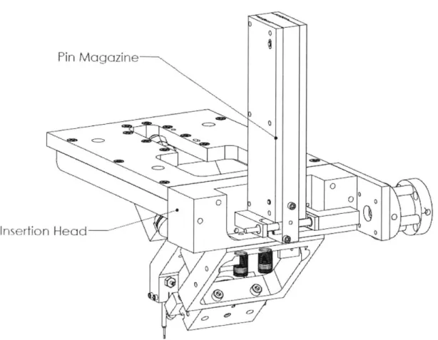
5.2 M achine Specifications...43 5.2.1 Pin M agazine...44 5.2.2 Insertion H ead ... 45 5.3 Final D esign ... 4 7 5.3.1 Pin M agazine...50 5.3.2 Insertion H ead ... 54 5.3.2.1 Chassis ... 55
5.3.2.2 Pin Escapem ent...56
5.3.2.3 Insertion A rm ... 58
6 D esign M ethodology ... 63
6.1 Pin M agazine...63
6.1.1 Pin Storage...63
6.1.1.1 Feeder Slide D w ell T im e...64
6.1.2 Pin Feeding to Insertion H ead ... 66
6.2 Insertion H ead...68
6.2.1 Pin Escapem ent...68
6.2.2 Pneum atic System ... 70
6.2.3 Insertion A rm B earing A rrangem ent...75
7 T e tging ... 83 7.1 Testing M ethodology ... 83 7.1.1 M ean T im e T o Failure ... 83 7.1.2 Cycle T im e ... 83 7.2 T esting R esults...84 7.2.1 M ean T im e T o Failure ... 84 7.2.2 Cycle T im e ... 84 7.3 Failure Characterizations...85 7.3.1 Critical Failures ... 85
7.3.1.1 Failure of a Pin to Exit the M agazine... 86
7.3.1.2 Galling Betw een M oving Parts ... 87
7.3.1.3 D ouble-Feeding pins...87
7.3.1.4 D rifting H ard Stops...88
7.3.2 N on-Critical Failures...88
8 Future W ork ... 9 0 8.1 M agazine ... 90
-8.2 Insertion H ead...90
8.3 O verall System Future W ork ... 9 1 9 Conclusions... 93
10 A ppendix ... 94
11 B i. m 8 b liography ... 97
12 B ill of M aterials ...
100
Chapter 1.
Introduction
Surface Mount Technology (SMT) is a commonly used method in the electronics industry to assemble components on a printed circuit board (PCB). SMT allows both sides of the PCB to be populated with components, as opposed to traditional through-hole technology, where the leads of electronic components are inserted and soldered into holes in the PCB, which prevents the opposite side of the PCB from being used to mount components. With SMT, the PCB can then be physically smaller than PCBs produced through traditional through-hole methods. This has led to SMT being adopted as the standard assembly method in the electronics industry.
A typical SMT assembly line is mostly automated with manual interaction limited to loading and unloading of PCBs, and setting up machines for production runs. The assembly begins with the application of solder paste using a stainless steel stencil on the regions of the board where components are to be placed. Next, a pick and place machine places components on these regions. Modern day pick and place machines are capable of placing as many as 30,000 parts per hour. The boards then pass through a reflow oven, which melts the solder paste and fuses the components to the PCB. The opposite side is populated with parts using a similar procedure.
Solder Place Solder Place
A i n Components Reflow Oven Pin Insertion - Board Flip Components Reflow Oven
Application (o)Appi cation (otm
Figure 1 - SMT line process schematic
Current enters and leaves the circuit through conductive input output (1/0) pins that are pressed into holes in the PCB. The pin insertion process takes place between the top and bottom side SMT
8-assembly lines. These pins come in various lengths and diameters and can be inserted into the PCBs either manually or using an automated pinning machine. Figure 2 shows a commonly used pin.
Figure 2 - Photo of typical pin in use (top); CAD rendering of pin (bottom).
1.1 Motivation
The advantages of an automated pin insertion machine are higher throughput, decreased labor requirements and higher parts traceability. Although there are numerous automated pinning machines available in the market, customizing a pinning system to a company's specific
requirements can prove to be a challenging task. Machines designed for pinning may not meet the reliability and throughput requirements that the company must achieve. Some of the common problems faced are:
" Reliably sorting pins from their loose state; " jamming of pins
0 Correct pin types being rejected by the system.
This thesis describes efforts in re-engineering the existing pinning machine at SynQor Inc., a designer and manufacturer of power supplies located in Boxborough, MA.
1.2 Objectives
The project proposed to re-engineer a pre-existing pinning system by creating proof of concept prototypes that demonstrate a valid mechanism for PCB pinning. The prototypes must be robust, cost effective, and flexible for unknown future pin types. The key objectives were as follows:
- Develop a system which reliably sorts, orients, and inserts pins from a loose bulk state into the PCBs;
- Improve upon the current machine pinning rate of inserting 8 pins in 16 seconds, with a target cycle time of approximately 8 pins in 10 seconds;
- Produce a system that is robust while remaining easy to repair and maintain; - Design flexibility into the machine for use with future product lines; and
1.3 Scope
The project scope was encompasses building a proof of concept automated pinning machine that could efficiently insert pins of one of most widely used pin types at the company. The focus was to design a working prototype of the pinning machine, so that the company could later convert it into a production-ready machine using the same principles and mechanisms present in the prototype. 1.4 Work Distribution
Early in the design process, the conceptualized pinning system lent itself to three main sub-processes:
e Sorting the pins from a loose bulk state to an oriented state; e Inserting the oriented pins into the PCB; and
e Developing the vision and control systems necessary for the two previous tasks.
The initial development of each process was done as a group, but further work was split among the group members. Michelle Chang worked on sorting the pins from a loose bulk state to an oriented
-state [1]. Rejin Isaac developed the vision and control system deployed in the project [2]. The author of this thesis developed the pin storage and pin insertion mechanisms.
Chapter 2. Pinning System
2.1 PinsThe main focus of this project is a specialized pin which is inserted into printed circuit boards (PCB). At its most basic, a pin is a cylindrical metal part with a collar. Figure 3 illustrates the
maximum dimensions and features of a pin typical to our application. In total, there are 24 different pin types of varying diameters and lengths. The three diameters pins are available in are 0.080", 0.062" and, the most commonly used, 0.040." Each of the three diameters has a selection of 8 different pin lengths depending on the application.
SECTION A-A
SCALE 2
: 1
0.035 SQUARE
A
A
INSERTION END
INTERFACE END
COLLAR
Figure 3 - Typical maximum 0.040" pin dimensions (inches)
2.1.1 Functionality
Pins are terminal components that are used to interface between the PCB and another product. They are attached to the boards with through-hole technology, that is, the pins are inserted
-(pressed) into holes in the board and soldered in place (see Figure 4). By connecting via a through-hole rather than a surface-mount pad, the pins can transfer electric current through the thickness of the circuit board, useful for making interconnects on a multilayer board. [3]
Figure 4 - Pins pressed into a PCB
These pins are used as interconnects between PCBs and other electronics external to the board they are mounted on. While one end of the pin is attached to the PCB, the other end may interface
directly with the through holes of another circuit board, with receptacle terminals on another PCB, or with flexible leads. [4]
The pin is attached to the board in a two-step process. First, the pin is inserted into a PCB with an interference fit from the square or hexagonal insertion head (0.040" pins have a square insertion end, and 0.062" & 0.080" pins have a hexagonal insertion head). Second, the pin is soldered to the board. This project focused on the first part of pin attachment - the pin to board insertion process.
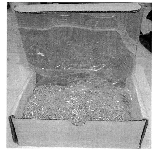
In addition to the features noted, the pins also have two chamfers on one side of on the pin collars, which prevent solder cavities from forming during the soldering process. The pins are lead free and plated with tin. They are manufactured on screw machines and delivered in bulk in a loose state (see Figure 5).
Figure 5 - Pins are delivered to SynQor in a loose state in boxes from the manufacturing company.
2.2 Existing Pinning Methods
There are currently three methods for pinning a PCB at SynQor. One of the methods, manual pinning, relies on an operator to manipulate the pin and insert it into the board. The other two methods are two different approaches to automating the pinning process. The three processes and the inefficiencies inherent to them are detailed in this section.
-2.2.1 Manual Pinning
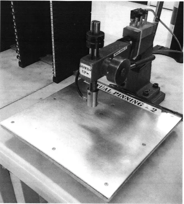
Pinning a board manually utilizes an arbor press with a special collet with negative pressure to retain the pin. To set up the process, the operator adjusts the depth stop on the arbor press by test inserting pins until the correct depth is achieved. Once this height is achieved and confirmed by measuring the depth, the operator locks the depth stop in place. At this point, the set up for the manual pinning process is complete.
Figure 6 - Arbor Press used for manual pinning. The head of the arbor press has a collet
attached to it to hold the pin with vacuum pressure.
The operator takes a pin from the box of pins, inserts the head of the pin into the collet, and then locates the circuit board under the press according to a drawing that details where each pin, and what type of pin, should be located. The board is populated with pins, and moved into a queue for the next process.
-The operators scan each board into the SynQor production tracking system as they are pinning it, as well as the box that they are pulling pins from. Tracking pins in this manner provides some level of part traceability, but is prone to errors since often times there are multiple boxes of pins available for the operators to pick from.
Currently, the manual pinning process is run with two to three full time operators for two shifts per day, depending on the workload. Manual pinning is labor intensive and costly. The goal is to reduce labor requirements with the process developed herein.
2.2.2 Automated Pinning - Flexible Automation
SynQor developed a pinning machine working in conjunction with an outside company in the early 2000s. The idea was to develop a process that allowed an operator to load up to 8 different pin types in vibratory bowls and have the machine feed pins, orient them, and then send them to an insertion machine to be inserted into the board without operator intervention.
The system works by feeding the pins with vibratory bowl feeders to a conveyor. The conveyor transports the pins past a line-scan camera where an image is developed from the "slices" that the camera takes. From the image that the system builds, it analyzes the pin and determines if it is the correct pin, and if it is in the correct orientation. Downstream from the camera, an arm picks up the pin and reorients it (if necessary), then sends it through a tube by means of compressed air to the insertion robot. The robot picks up the pin and positions it at the correct point over the PCB and presses the pin to the correct depth.
Figure 7 - Dual-gantry pinning system
This machine was used in production for approximately one year when they first purchased it, but it was prone to failures. The machine struggled to deliver pins reliably to the insertion robot. There were issues with pins jamming at certain points in the system -frequently in the tube that delivered pins from the sorting mechanism to the insertion robot. The sorting mechanism was often not able
-to identify and re-orient pins fast enough -to keep up with the pace set by the insertion robot. This often led to the insertion robot sitting idle while it waited for a pin.
The positioning system (a dual-gantry Cartesian robot - see section 3.3) from this machine, as well as the production system interface (barcode scanning, board programming) will be re-used in our project in its pre-existing form, with little modification.
2.2.3 Automated Pinning - Specialized Automation
Another pinning process was developed by SynQor with an outside company. This system,
decidedly less "flexible" in terms of the variety of pins it can handle, as well as how it handles faults, employs vibratory bowl feeders to feed and orient the pins. The bowl feeders are customized to accept and sort different pin types. The pins are sorted mechanically by taking advantage of the non-symmetric design of the pins which allows the bowl feeders to reject pins that are not in the desired orientation.
Once the pins go through the sorting and orientation process, they line up in a queue upstream from an escapement. The escapement picks off one pin from the queue of pins and drops it down a tube to send it to the insertion head. The board is positioned under the insertion head and a pin is driven to the desired depth.
Figure 8 - The vibratory bowls of this pinning system can be seen atop the machine enclosure. These bowl feeders send pins to the insertion head inside of the machine.
This system suffers from frequent jamming in the bowl feeding/escapement area of the process. Since the bowl feeder is vibrating, some pins can ride up on each other and cause the queue to jam which requires an operator's attention to clear the jam. The positioning system in this machine has very little in terms of feedback to know if it has pressed a pin correctly.
2.3 Developed Solution
The team has developed a pinning process that accepts pins in bulk (loose) then sorts and
transports them to an insertion head that orients the pins for insertion into a PCB. The processes of sorting and insertion have been decoupled by means of a "pin magazine" that stores pins between the sorting and insertion process. A systems level overview of the process is given in this section.
-20-2.3.1 Overall Pinning Process/Final Design
The pinning process consists of two major sub-processes: sorting and insertion. The two processes were run in series in past attempts to automate pinning, which resulted in the sorting process holding up the insertion process quite often due to jams or other faults. The decision was made to "decouple" these two processes in our approach in order to be able to run the processes in parallel without running into any issues where one processes causes the other to slow or stop.
Figure 9 - Pinning Process Diagram
The system was decoupled in between the sorting and insertion sub-processes (see Figure 9) by designing a magazine to hold a determined quantity of pins that would act as the interface between the sorting process and the insertion process.
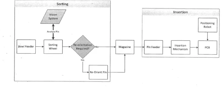
A high-level overview of the developed pinning processes is shown in Figure 10. Figure 11 shows the actual magazine used to interface between the two sub-processes. Sections 2.3.1.1 and 2.3.1.2 describe, in more detail, the sub-processes of sorting and insertion.
Inseftion
M4C~1misrfl
-Figure 10 - Developed pinning process showing the breakdown into the sorting and insertion sub-processes.
0 0
C
0
Figure 11 - Magazine used to interface between sorting and insertion process
2.3.1.1 Sorting
The process of sorting pins brings the pins from the loose state that in which they are delivered to SynQor and aligns them in the pin magazine. The sorting process utilizes vibratory bowl feeders to "singulate" the pins, and then transports them to a rotating wheel that grips the pins and brings
-22
them in front of a camera. [1] The camera and the accompanying vision system analyze the pin and determine if it is in the correct orientation and if it is the correct pin. After the camera stage, the pin either is sent directly to the magazine if it is in the correct orientation, or it gets sent to a
reorientation stage before being sent to the magazine. [2] Incorrect or damaged pins can be ejected into a waste bin at the last station on the wheel.
The sorting process is something that will be done away from of the production floor, likely in the stockroom. When pins arrive at SynQor, operators will run them through the sorting machine to populate the magazine so the magazines are ready for the production floor.
2.3.1.2 Insertion
Once the pins are sorted into a magazine, the insertion process can begin. The insertion machine will consist of two gantry-style Cartesian (see section 3.3) positioning robots. Both robots will carry
insertion mechanisms. In all, one gantry will have an insertion mechanism for 0.040" diameter pins and 0.062" diameter pins, and the other will have a mechanism for 0.080" diameter pins and an additional mechanism for 0.040" diameter pins. The 0.040" pins are the highest volume pins run at
SynQor, so there are two insertion heads (one on each gantry) to handle them so the workload can be balanced between the two gantries.
The insertion mechanism utilizes the part feeder integrated into the magazine to pull pins off of the bottom of the stacks and shuttle them to the eject port of the magazine. Once a pin has been
shuttled to the eject port, it is sent to an insertion tube that rotates to orient the pin vertically. From here, the positioning gantry will locate the pin over the correct hole on the board and proceed to
drive the pin down to the correct insertion depth.
The process will repeat until a magazine is depleted, or a new pin type is required for the board. In either case, the positioning robot can automatically unload an empty or un-needed magazine, and load a new one from a magazine storage rack located within the positioning robot's work envelope. 2.3.2 System Components
There are a number of features already implemented in the positioning system that have been developed prior to the start of this project at SynQor. We have re-used a number of these features as part of the pinning process.
The positioning system has the ability to scan the barcode located on each PCB to determine the correct part program to run for that particular board. This allows the machine to change product assemblies without operator intervention since multiple pin types can be loaded into the magazine rack.
A product-programing interface has also been developed to allow engineers to easily program new PCBs. This makes the pinning machine very flexible when introducing new products to the
assembly line.
-24-Chapter 3. Automation
The transition to automated assembly processes from manual processes has been the focus of a number of companies that perform repetitive, semi-skilled assembly tasks to build a product. This is especially true in high-wage regions. The pinning system discussed in this thesis is a good example of the justification for automation, as well as the development process to design an automation process and the accompanying equipment.
As such, it is important to have an understanding of how industrial automation came to be what it is today, and where the current focus is on advancing the field. This section aims to give the reader an overview of automation to set up the context for the process and equipment design discussed later on.
3.1 Defining Automation
At its most basic, automation can be defined as the use of machines that make a manufacturing process more efficient. The machines combine operations or have skills that are not easily acquired by a human workforce. But automation is not simply making a single process automatic;
automation is the automatic handling and continuous processing of a machine, made possible with computer control. Automation processes can be considered part of the more general category of computer integrated manufacturing (CIM). [5]
It is important to differentiate automation from mechanization. Mechanization is doing work with machines. That is, operators use machinery to assist them in completing the bulk of their work. Automation reduces the human physical labor component by making much of the work automatic,
controlled by computer technology. Automation operators serve a supervisory role over the automation machinery, as opposed to direct interaction with the machine as it performs its assigned task. [6]
Automation is characterized by the use of electromechanical devices such as motors, servos, hydraulic and pneumatic systems; an increase in the productivity of a given process; improved precision and reproducibility; and a decreased labor force in purely physical work.
3.2 Brief History of Automation
The advent of automation as we have defined it came hand in hand with the development of the more complex control systems, chiefly through advances in digital computing. The term automation itself was first used at the Ford Motor Company in 1945 to describe the combination of automatic handling and continuous processing in machines. [5]
The roots of automation can be traced to the electrification of factories. As it became possible to provide machines with electric motors, many already mechanized processes were combined in machines, and factories were able to implement "continuous-flow" mass production. These machines were all tooled specifically for their tasks though use of cams. The need for more flexible and sophisticated machine control became evident. Numerical control (NC) grew from this need. [7] Numerical control is what drives much of modern precision machining. This positioning control is the technology behind the CNC (computer numerical control) machines that are viewed as a trademark of automation.
Early forms of machine control included cams and tracing machines, but these methods were not abstractly programmable. The development of the servomechanism and the subsequent selsyn (basically two servos together) meant it was possible to have highly accurate measurement information. The idea of combining this positioning system with a numerical calculator was first brought together by John T. Parsons in the 1949, with punch card readings as the calculator. [7] The first working NC machine was developed at MIT in 1952 - a complex design involving a punch tape input, relay-based hardware registers, and many encoders and moving parts. The following decade showed many improvements to CNC systems, but it was not until the proliferation of minicomputers in the 1960s that the use of CNC machines became widespread. [7]
This positioning control technology has had usage beyond the field of machine tools. The precision positioning systems developed for machining have been extended to control of autonomous robots, many in the service of factory automation. The first such robot was the Unimate, used in a General Motors plant in 1961. The robot moved die castings and did welding, jobs considered extremely dangerous for human laborers. The trend in automation has continued today, with many robots doing the duties that humans cannot or would not want to perform. [7]
-26-3.3 Dynamics/Configurations
There are a number of different configurations of industrial robots, each suited for different tasks. Each robot is a combination of different types of linear or rotational joints that can be manipulated in order to reach the desired position. Common configurations include the SCARA robot (Figure 12), typically used for simple pick-and-place type operations, Articulated robot (Figure 13), which has the dexterity and similar joint structure to a human arm, and the Cartesian coordinate robot (Figure 14), which is often seen in a gantry configuration [8]. Each robot has a characteristic work envelope that represents the volume that the robot can reach with its end effector.
Figure 13 - Typical articulated arm robot with work envelope shaded in grey [10]
-Axis 3
Axis 1
Figure 14 - Typical gantry robot [11]
The gantry (Cartesian) robot configuration used at SynQor provides a robust structure to position objects in 3D space. Unlike the other two configurations shown (SCARA and articulated arm), the
-gantry configuration's axes are well supported on both ends, and do not have any cantilevered joints or frame members. Well supported joints and frame members deflect less under load, which increases the positioning accuracy of the robot.
A robot has three main coordinate systems which represent its work envelope. These coordinate systems are [12]:
- Joint Coordinates: coordinates that store the exact position of each joint in the robot to reach the desired end effector position. These coordinates are stored as positions of each joint relative to a local reference frame.
- World Coordinates: describe the position of the end effector relative to a fixed coordinate frame attached to the ground. In some cases, multiple joint orientations might satisfy the desired world coordinate position.
- Tool Coordinates: a coordinate frame is fixed to the center point of the tool on the robot. Using the tool coordinates, the robot can be programmed incrementally, without dealing with the kinematics of the robot itself since all motions are relative to the tool.
Robots can be programmed in a variety of manners. On-line programming involves programming the robot directly, which often requires taking the robot out of the production process. Off-line programming, however, utilizes computer simulation or a physical model of the robot to program the desired motions. Once the program has been generated off-line, it can be uploaded to the robot on the production line, which minimizes downtime compared to on-line methods.
Programming the motion of the robot can be accomplished in a number of ways. Text based programming methods with proprietary languages such as AIM, or V+, as well as general motion control languages that are based on Visual Basic or C can program precise motions of the robot, as well as take advantage of conditionals and loops within the program. Physical programming methods include teaching the robot points by physically moving the end effector to the desired position, then recording the sequence of points; as well as playback programming which involves teaching the robot the path it should follow between points to have more control than point to point motions.
gripping mechanism can physically grip the part with pneumatic or electric actuation, or it can hold the part via vacuum, or magnetics. Robots that hold a tool used in a production process will often have specialized end effectors to accommodate that tool and the accessories that go along with it. [12] [8]
3.4 Economics of Automation
With the increasing cost of labor in developed countries, automation has gotten a lot more attention from manufacturing companies that wish to continue manufacturing in high-wage environments. Additionally, with the increasing cost of labor, the price of industrial automation (i.e. robotics) has been decreasing steadily.
Cost of Robotics & Manufacturing Labor
160 140 120 180 80Cost of Robotics 60r====Cost
of Labor 40 20 0 OVVFigure 15 - Cost of robotics versus manufacturing labor [13]
In addition to the financial reasons to use automation, automation can also relieve humans from performing dangerous, hazardous, or menial tasks that are not well suited for humans to perform. Tasks that involve hazardous chemicals or materials, are performed in clean-room environments, or operate in hard-to-reach places are particularly well suited for robotics.
-30-3.5 State of the Art
Current automation research focuses on two main areas:
- Increasing the "intelligence" of robotics through machine learning and vision systems, and
- Increasing the speed and accuracy of existing robotic systems. 3.5.1 State of the Art of Machine Vision
Machine vision has revolutionized the field of manufacturing automation by decreasing the time required for processes like inspection, counting, gauging, defect detection, thereby reducing labor requirements significantly. The advantages lie in the fact that these processes are carried out with more precision, have become faster and more reliable. Industrial machine vision systems are deployed in almost all industries like semiconductors, electronics, automotive, pharmaceutical and food packaging.
Cameras used in present day vision systems are based on Gigabit Ethernet (GigE) vision interface standard that allows data transfer rates up to 1000 Mbit/s [14]. Acquisition speed is an important parameter that defines how fast the system can capture and process images. Today, the fastest systems in the world can process up to 500 frames per second [15]. On the other hand, the size of the camera and the on board processor has decreased. The smallest camera available in the market is 30mm X 30mm X 60mm [16]. It must be noted that the processor is also embedded inside this tiny camera, making it an efficient inspection system where space is a constraint.
Along with the hardware, a lot of development has taken place in vision software to enhance image-processing capabilities, capture more intricate details of the image and provide better results. Multi-core processors significantly reduce the processing speed and also enable controlling of up to 8 cameras simultaneously [17]. Some of these processors have additional features that can handle I/O from various systems, thereby eliminating the need for a separate PLC [18].
Features like pattern matching and edge detection have been the most commonly used features in machine vision systems. But in recent years, developments in computer algorithms and processing speeds have facilitated the introduction of newer features for image editing and processing.
Present day vision systems are not just cameras connected to a powerful processor, but also possess various sensors needed in manufacturing automation. One of the most commonly used sensors in industrial automation is the photoelectric sensor. All-in-one industrial inspection systems with embedded photoelectric sensors, camera, lighting and optics capable of inspecting up to 6,000 parts per minute are revolutionizing the world of manufacturing [19]. These low form
factor inspection systems eliminate the need for expensive fixturing and simplify the overall system design. Most vision systems have a fan less design making them conducive to be used in clean room environments [17].
Systems with network protocols like RS-232, RS-485, and Ethernet built on them enable multiple systems to be controlled all at once via a LAN or VPN connection. Additionally, some software also provides web based monitoring of the production process, thereby reducing manual interference to the bare minimum [20]. All this makes the remote management of systems and generation of production reports very easy to achieve.
Machine vision is being integrated with robots to help them make judgments on the basis of what they 'see'. Machine vision based robots are being used in solar cell manufacturing to enhance the throughput and quality [20]. Most components used in solar cells are delicate and small, and require complex assembly. Physical tracking through conveyor encoders require additional tooling and fixtures, which can be eliminated by vision based inspection, thereby bringing considerable savings.
-32-Figure 16 - Parallel configuration robot used in solar cell manufacturing [21]
The industry is slowly moving towards 3D machine vision. 3D vision helps in capturing details about the depth of the object [22]. This is especially used in semiconductor and food industries, where thickness of the object plays an important role and also in inspection of molded parts to look for defects.
In this age of economic sluggishness, as manufacturers try to keep manufacturing competitive despite increasing labor prices and competition from cheaper markets, machine vision based manufacturing automation helps bring in cost effectiveness by reducing both labor and footprint. 3.5.2 Robotic Improvements
The speed and accuracy of a robot is a factor of the structural design of the links between the different joints, the power that the joint actuators can provide, and the resolution to which the joints can be controlled.
Currently, the fastest robot on the market is the Adept Quattro robot, which has a parallel
configuration of four arms (see Figure 17). The Quattro has a payload capacity of 6kg, a maximum speed of 10m/s, and a repeatability of +/- 0.1mm.
Figure 17 - Adept Quattro parallel configuration robot [23]
-Chapter 4. Robotic End Effectors
In order for robots to perform the task they're programmed to do, they need special end effectors affixed to them. These end effectors, often referred to as "part grippers," or "tooling," can take a variety of form factors depending on the task at hand. End effectors are typically attached to the robot's "wrist" - the end of the kinematic chain formed by all of the robot's links and joints. [8]
Robots designed to perform an operation such as welding or adhering will have an end effector that includes the tool to perform that operation as well as a method for feeding the consumed material
(i.e. glue, welding material) to that tool. Other robots designed for mechanical assembly of parts will have end effectors designed to grip the parts so the robot can pick it up and manipulate it to the
correct location.
The insertion head designed for the pinning machine is a form of an end effector in that it manipulates a part to the proper orientation, and is then translated by the robot to the desired position. Common end effectors are discussed in this chapter, with a focus on design types particularly applicable to the pin insertion process.
4.1 Types of End Effectors
The two categories of end effectors are tooling and part grippers. These parts are often highly customized in order to accomplish the task the robot is assigned to perform.
4.1.1 Tooling
Robots require customized tools in order to perform an operation on a work piece. These tools can include powered screwdrivers, welding guns, and de-burring tools (see Figure 18).
4
jyl'
Figure 18 - Articulated arm robot with welding tool (left) [24]; SCARA robot with automatic screwdriver (middle) [25]; Articulated arm robot with de-burring tool (right) [26]
A robot is responsible for moving the tool relative to the work piece in a predetermined path. Often, the robot will also control the operation of the tool by sending signals to control the action of the tool. Parameters such as turning the tool on or off, dispensing material, or controlling the rotation speed and direction are common features for the robot to control.
Tooling can be designed so a robot can change tools during its programmed cycle. Situations where a robot needs a different size tool bit or a different tool altogether can be accompanied by designing a quick-change coupling between the robot and the tool. A "tool change" can be programmed into the robot's work cycle to allow it to automatically set the current tool in the corresponding tool holder (usually fixed in space) and to move to another tool holder to pick up a new tool - all without operator intervention. Switching tools rather than trying to design one tool to perform all the operations that the robot is required to do reduces the total mass that the robot must carry around when it's making it's movements on its programmed path. Reducing the mass that the robot must carry around increases the speed at which the robot can travel between points.
-36-4.1.2 Part grippers
Part grippers, unlike tooling, are designed to hold the work piece in order to transport it to a new location, or to hold it while an operation is being performed to it. Grippers can take many forms including the following:
* Mechanical grippers, * Pneumatic grippers,
e Magnetic grippers, and
e Others, such as cryogenic grippers, simple hooks, and adhesive grippers.
Figure 19 - Mechanical grippers [27]
Part grippers often perform assembly tasks where they must pick up the work piece from a station (sometimes on a moving conveyor, or a pallet) and attach it to the assembly at another location. The shape, weight, and material of the object being handled, as well as the required re-orientation movements in order to assemble the part all have an effect on how the gripper must be designed. Simple mechanical grippers (Figure 19) can generally be found as standard components sold by companies that design and manufacture robotics. But, more complex grippers to handle uniquely
Grippers can be designed to include various sensors to protect the robot and the work piece it is handling. Often, the robot is programmed to sense if a part is present in the grippers, and also to monitor the amount of force being applied to the part.
4.2 Design Considerations for Part Grippers
Objects that are of a common shape (cube, sphere, or other simple polygonal shapes) can often be handled with off-the-shelf mechanical grippers and generally require little customization in order to effectively transport the part.
When unique parts must be handled, customized grippers must be designed for that specific part. Part characteristics that make a part unique include:
" fragility, e mass,
e coefficient of friction, e size, and
e Part presentation.
The accuracy and speed at which parts must be transported dictates most of the design process when designing part grippers. The design engineer must make a tradeoff between gripper stiffness and gripper weight to satisfy the requirements; grippers that deflect a considerable amount when carrying a payload, or during acceleration, will reduce the accuracy of the part placement because the robot usually does not account for this deflection. However, designing a gripper too robust will increase the mass of the gripper itself, and will reduce the payload capacity of the robot as well as the maximum speed at which it can travel. The robot must be able to carry the mass of the part gripper and the part together, since these two objects travel together on the robot's wrist.
-38-Close
Open
Figure 20 - Mechanical grippers showing the open and closed state [28]
Mechanical part grippers (such as the jaws shown in Figure 19 and Figure 20) must provide sufficient clamping force to hold the part via friction between the jaws and the surface of the part. In pneumatically actuated grippers, this friction is controlled by the amount of pressure used to clamp the jaws shut. The friction force generated must be greater (by a certain safety factor) than the force due do gravity, and the force due to accelerations generated by the robot combined. Part fragility must be considered when designing the gripping pressure to be used. In certain cases with particularly fragile work pieces that are to be gripped by mechanical grippers, different materials may be used to increase the coefficient of friction between the part and the gripper jaw. Lifting glass objects with aluminum grippers might not provide enough friction to securely hold the part since the coefficient of friction between glass and most metals is 0.20. In order to increase friction without increasing the clamping pressure, the design engineer can add rubber pads to the part grippers which have a coefficient of friction of 0.90 - thus providing more friction force from the same clamping pressure. [28]
In addition to considerations about the part itself, attention must be paid to the manner in which parts are presented to the gripper. There are a number of different ways parts are commonly presented for manipulation by a robot. Some common presentation methods include:
" Parts fed to a robot's work envelope by means of a conveyor.
* Parts are "fed" to the gripper without requiring the robot to move to a location to pick up the part. This is a common method used for lightweight parts that can be fed down a tube with air pressure.
In the first two cases where the robot must move to a location to pick up a part (usually from an array of parts), the amount of space between parts and the orientation of the parts must be considered. Parts that are spaced closely together need grippers that can fit between the gap between the two parts in order to successfully pick up and manipulate the part without interfering with neighboring parts.
The orientation of parts is also of importance in the design of the gripper. If the parts are presented in the same orientation each time to the gripper, or if the parts are symmetrical about all axes, the gripper can be designed to handle the part in just one orientation. However, if the parts are presented in a random fashion to the gripper, consideration must be taken to ensure that the gripper can successfully handle the part in all possible orientations. Grippers with multiple geometry features on them can be designed to handle all orientations of certain parts.
Lightweight parts, such as nuts, bolts, or particularly for this thesis, small pins can be fed directly to the part gripper on the robot. Since the weight of these parts is usually negligible relative to the payload capacity of the robot, many parts can be stored at the part gripper directly (in some kind of local part feeder); or, parts can be sent to the gripper by sending them through a tube with
compressed air, for example. This kind of part presentation reduces the required motions of the robot to complete the programed task and allows the robot to place components faster.
4.3 Applications to the Pin Insertion Process
The pins in this application are small, lightweight components that lend themselves to being stored locally at the point of use on the part gripper itself. As such, the part gripper, referred to as the insertion head, is designed to store and feed the pins in a specially designed magazine. The
magazine presents the pins to the insertion head in a consistent orientation. Delivering the pins in a consistent orientation means the insertion head can be optimized to work for that orientation, and does not have to handle different part orientations.
Having a large amount of pins available to the insertion head minimizes downtime spent waiting for a pin to feed, and allows the robot to focus its time on actually inserting pins into the PCB.
-40-As discussed with tooling, the magazines as well as the insertion head were designed to be able to be changed by the robot without operator intervention. Each insertion head gantry has the ability to change insertion head tools to switch to a different diameter pin as well as the ability to change magazines to switch to a different pin type within that diameter, or to load a new magazine once the current one has been depleted.
Designing these parts to be interchangeable reduces the mass that the robot must carry while making moves since it does not need to carry an insertion head for pin types not currently required. Additionally, the ability to switch parts automatically by changing to a new magazine minimizes the amount of time required by an operator to set up the machine between production runs.
Chapter 5. Machine Design of Magazine and Insertion Head
The manual pinning process and the specialized automation process are still in use at SynQor as the primary methods for pinning a PCB. The pin insertion process discussed herein will become part of a pinning system to be used in production at SynQor. The systems designed in this group of theses will be further developed at SynQor to bring them to a production-ready state. The pinning system will incorporate a pin sorting machine [1], a pin insertion machine, a magazine to interface between sorting and insertion, and a control system to act as the director of all the subsystems [2].
The focus of this thesis is on the design and development of the pin magazine and the pin insertion mechanism. This chapter will describe the design specifications, the concept development process, and the final mechanical system design of the magazine and the insertion head mechanisms. 5.1 Project Scope
The pin insertion project described herein was developed to provide a new concept for a reliable and robust method to pin PCBs. The end-goal was to have a proof of concept prototype that was able to successfully orient a pin and grasp it for the pin insertion process. This proof of concept would later be attached to the existing positioning robot, and accordingly, must physically fit into the work envelope of the robot.
The basic design requirements of the pin insertion machine are: * Ability to insert pins into a PCB at a rate of 1 pin/second; e Run without operator intervention for approximately 4 hours;
e Ability to support the pin during pin insertion, and withstand the associated forces of 231bf;
" Modularity, to allow for future integration into other types of pinning systems; " Minimal complexity, for ease of manufacture and repair; and
e Reliability, to limit downtime caused by mechanism faults such as pins or components
jamming.
The cycle time of 1 pin/second corresponds to the total throughput of the pinning machine when the insertion mechanism is attached to the positioning robot. As such, the cycle time of the insertion mechanism must budget time for the positioning robot to make the required moves between holes to be pinned on a PCB.
-42-Similarly, the design requirements of the pin magazine are:
" Ability to feed pins to the insertion machine at a minimum rate of 1 pin/second to keep up with the insertion machine;
" Repeatably attach to the insertion machine by means of a locating mechanism; and " Inexpensive to manufacture to reduce the cost of manufacturing a large number for the
production version of the process.
Once a working prototype was established, the machine was to be tested to determine if it met the performance requirements. Additionally, the failures of the machine were to be quantified in terms of how often they occurred, and what the typical cause for a failure was.
5.2 Machine Specifications
Early in the design process, a number of key decisions were made that would ultimately control how the pin insertion mechanism functioned. A pin magazine was required as a result of the decision to "de-couple" the sorting and insertion process. The pin magazine would serve as an intermediate storage mechanism that would hold the pins in the orientation that the sorting process delivers them in. This pin magazine, would act as the interface between the upstream and downstream processes of sorting and insertion, respectively. As such, the sorting machine filled the magazine with pins, and the insertion mechanism was required to remove these pins from the pin magazine and transport them to, and press them in a PCB.
The developed pinning machine consists of three main components:
e Pin magazine; e Insertion head; and
* Positioning robot.
In designing the specifications for this machine, we took into account aspects of the machine that will be developed in the future and implemented with the insertion head mechanism. The goal for the pinning process (outside the scope of this project) is to have the dual gantry positioning robot equipped with:
" Two insertion heads per gantry, for a total of four insertion heads (one each for the two least common pin types, and two for the most common pin type); and
e Storage for additional magazines within the robot's work envelope.
Each insertion head mechanism will be designed to be automatically changed by the robot without operator intervention. This means each gantry can utilize both insertion head mechanisms (for the different pin diameters) without requiring an operator to physically switch the insertion heads. Each gantry will also have within its work envelope a "magazine storage rack" that will enable the robot to automatically switch magazines when required.
5.2.1 Pin Magazine
The pin magazine is the interface between the sorting and insertion sub-processes. It must store pins that have been sorted and oriented and deliver them to the insertion mechanism in a reliable manner. Once the magazine is populated with pins from the sorting sub-process, it must hold the pins securely and contain a mechanism to singulate the pins to deliver them to the insertion head. The magazine must be capable of storing enough pins to allow the insertion mechanism to run without operator intervention for approximately 4 hours in order to minimize the labor
requirements to run the insertion machine. The target of pressing a pin at a rate of 1 pin/second yields:
pin pins_
1 = 14,400 pins 5-1]
second 4 hours
With a pin magazine that can store 250 pins, two simultaneous gantries operating, and two internal magazine storage racks per gantry that are capable of holding and automatically changing
magazines with a storage quantity of 30, that yields a total unattended pinning time of:
pins magazines gantries pins
250 . * 30 * 2 = 15,000 [ 5-2]
magazine gantry robot robot
15,000 pins1500robot-1
1 pin = 15,000 seconds unattended [ 5-3]
second
-15,000 pins = 4.17 hours unattended
There are two shifts per day at SynQor, with a total working time of both shifts combined of roughly 16 hours. An interval of 4 hours between when operators must re-stock the machine with
magazines means that the pinning machine will require operator attention four times each day. In addition to the storage requirements, the magazine must be capable of delivering pins
individually to the insertion mechanism. The mechanism to deliver pins must operate within the time window of 1 pin per second, while still leaving enough time for the insertion mechanism to successfully pin a board in the remaining time.
These magazines are being used in a production environment, and will be frequently moved by operators from an inventory area to the production floor. As such, the magazines need to be designed to be robust enough to handle the normal wear that occurs in a production environment. This means that fragile components need to be designed out, or if they are absolutely necessary for the mechanism to work, they should be properly protected from damage.
The weight of the payload on the robot, which is the weight of the magazine and the insertion head combined in this case, should be minimized to allow the robot to accelerate between points as quick as possible.
5.2.2 Insertion Head
The insertion head is a robotic end effector that is customized to handle the pins in this application. The insertion head is responsible for the task of accepting a pin from the pin magazine and
orienting it vertically in a manner that allows the positioning robot to press a pin into a PCB (see Figure 21).
I
Feed Orientation PinT
6
h
Insertion Orientation PCB Insertion HoleFigure 21 - Insertion head pin reorientation
The insertion head is the main structural component of the whole insertion mechanism. As such, it needs to be designed to be able to perform the following tasks:
" Support a load of 231bf when pressing a pin into a PCB;
" Mechanically advancing the pin feeder in the pin magazine in order to feed a pin; " Grasping a pin securely after it has been delivered from the pin magazine;
" Re-orienting the pin from the horizontal position as it is delivered to the vertical position for pressing into a PCB; and
" Firmly and repeatably holding a pin in the vertical position during the pressing process.
-46-Also to be taken into consideration is:
" The weight of the insertion head. In order to improve performance of the positioning robot, the insertion head should weigh as little as possible to reduce the payload on the robot.
e The number of actuators, sensors, and controlled axes of motion. Each actuator or sensor
requires an additional input or output from the machine control unit. [2] 5.3 Final Design
The pin magazine is a sub-assembly that is capable of holding roughly 250 pins. These pin magazines will be controlled in inventory by SynQor's production control software. The software will keep track of how many pins are left in each magazine, and what pin type is stored in the
magazine. The magazine is responsible for pin storage, as well as pin feeding and transportation to the insertion head. Detailed design of the magazine can be found in Section 5.3.1.
The insertion head is the mechanism that accepts pins from the magazine and orients them for insertion in the PCB. Once the pin is fed from the magazine, the insertion head takes the pin from its horizontal orientation and re-orients it vertically. In the vertical position, the pin can be pressed into the PCB. Detailed design of the insertion head can be found in Section 5.3.2.
Insertion Head-
-~~
Figure 22 - The insertion head and magazine
The positioning robot will serve as the control of the pinning machine. The insertion head and magazine will both be fixed to the carriage on the positioning robot's axes. The positioning robot is responsible for moving the insertion head to the correct position in the XY plane relative to the PCB, and then descending in the negative Z direction to press the pin into the circuit board. The
coordinate frame about the PCB is shown in Figure 23.
-48-Figure 23 - Board coordinate frame in the positioning robot. The origin lies on the top plane
of the PCB.
The positioning robot was not designed as a part of this project. It was designed and built
previously for another pinning process, and is being re-purposed for this pinning project. As such, the design and specifications of the positioning robot are not discussed in detail in this chapter. The positioning robot also has auxiliary functionality that includes:
" Scanning incoming PCB barcodes to determine the correct pin type, and pin locations used for that PCB;
" Calibrating new tools when repair or maintenance is performed to the insertion head; and
e Various diagnostic features.
The pins begin the insertion process in the magazine. A feeder mechanism within the magazine delivers pins to the insertion head, and subsequently the insertion arm. The insertion arm orients the pins vertically so they can, finally, be pressed into a PCB.
Pin Magazine Insertion Arm Orientation - -Insert into PCB
Figure 24 - Insertion head process schematic. 5.3.1 Pin Magazine
The pin magazine consists of two pin tracks side by side to each other. The pin tracks are each capable of holding 70 0.040" pins. The pins are stored parallel to each other in the pin tracks. At the bottom of the pin tracks, there is a feed mechanism that has a slide with a recess in it designed to accept a pin from one of the tracks and shuttle it to the centerline of the pin magazine. At the centerline of the pin magazine, the pin is in line with the insertion tube in the insertion head. The magazine then pushes the pin with compressed air out of the magazine towards the insertion tube. The process repeats until the magazine is depleted or a new magazine is called for by the machine control.
Figure 25 shows a basic layout of the pin magazine. The pin eject port is the point at which the pin is ejected from the magazine and sent to the insertion head. The feeder slide is actuated back and forth to feed pins off the bottom of the stacks of pins in the pin tracks and bring them to the pin eject port. Figure 26 shows the motion of the feeder slide when feeding a pin. And, finally, Figure 27 shows the path of the pin out of the magazine after the feeder slide has brought the pin to the eject port.
-,in
Tracks
Feeder Slide
'-Pin Eject Port
Figure 25 - Magazine assembly (left); open magazine assemblywithin the pin tracks (right).
Pins
showing pins stacked
Pin
Tracks
(hidden)
0O
4-O
Feeder Slide
t...,-Eject Port
Figure 26 - Motion of the feeder slide when feeding a pin. The slide is forced to the left which brings a pin from the pin track in-line with the eject port.
- 52
-Pin
... ...A
SECTION A-A
To Insertion
Head
-Air
Port
:*==a=
Compressed
Air
DETAIL B
Figure 27 - Section view showing path of pin being ejected from the magazine towards the insertion head.
5.3.2 Insertion Head
The insertion head is the end effector that will be attached to the positioning robot that holds a pin for insertion into a PCB. There are three sub-systems of the insertion head:
* Chassis;
" Pin Escapement; and " Insertion arm.
Insertion
Arm
Pin
Escapement-"-Chassis
Magazine Feed Cylinder
Figure 28 - Insertion head assembly (shown upside down for clarity).
-54-Insertion Arm
Pin Escapement
Figure 29 - Insertion head assembly side view (broken-out view to show pin escapement).
5.3.2.1 Chassis
The chassis for the insertion head serves a number of functions. In addition to being the "backbone" for all the auxiliary components included in the insertion head, it:
" Mounts and locates the pin magazine
" Provides a physical guide for pins to move from the magazine to the pin escapement; and " Locates the insertion arm relative to the magazine.
Figure 30 shows an isometric view of the insertion head chassis, and labels the important functional areas of the assembly.

![Figure 12 - Typical SCARA robot with work envelope shaded in grey [9]](https://thumb-eu.123doks.com/thumbv2/123doknet/14678769.558706/27.918.195.705.400.617/figure-typical-scara-robot-work-envelope-shaded-grey.webp)
![Figure 13 - Typical articulated arm robot with work envelope shaded in grey [10]](https://thumb-eu.123doks.com/thumbv2/123doknet/14678769.558706/28.918.145.735.119.438/figure-typical-articulated-robot-work-envelope-shaded-grey.webp)
![Figure 16 - Parallel configuration robot used in solar cell manufacturing [21]](https://thumb-eu.123doks.com/thumbv2/123doknet/14678769.558706/33.918.283.621.130.500/figure-parallel-configuration-robot-used-solar-cell-manufacturing.webp)
![Figure 18 - Articulated arm robot with welding tool (left) [24]; SCARA robot with automatic screwdriver (middle) [25]; Articulated arm robot with de-burring tool (right) [26]](https://thumb-eu.123doks.com/thumbv2/123doknet/14678769.558706/36.918.118.779.151.515/figure-articulated-welding-scara-automatic-screwdriver-articulated-burring.webp)