HAL Id: hal-03145728
https://hal.sorbonne-universite.fr/hal-03145728
Submitted on 18 Feb 2021
HAL is a multi-disciplinary open access
archive for the deposit and dissemination of
sci-entific research documents, whether they are
pub-lished or not. The documents may come from
teaching and research institutions in France or
abroad, or from public or private research centers.
L’archive ouverte pluridisciplinaire HAL, est
destinée au dépôt et à la diffusion de documents
scientifiques de niveau recherche, publiés ou non,
émanant des établissements d’enseignement et de
recherche français ou étrangers, des laboratoires
publics ou privés.
épaisseur
Massimiliano Casaletti, Guido Valerio, Oscar Quevedo-Teruel, Paolo
Burghignoli
To cite this version:
Massimiliano Casaletti, Guido Valerio, Oscar Quevedo-Teruel, Paolo Burghignoli. Application des
métasurfaces aux antennes à faible épaisseur. Comptes Rendus Physique, Centre Mersenne, 2021, 21
(7-8), pp.659-676. �10.5802/crphys.20>�. �hal-03145728�
Comptes Rendus
Physique
Massimiliano Casaletti, Guido Valerio, Oscar Quevedo-Teruel
and Paolo Burghignoli
An overview of metasurfaces for thin antenna applications
Volume 21, issue 7-8 (2020), p. 659-676. <https://doi.org/10.5802/crphys.20> Part of the Thematic Issue: Metamaterials 2
Guest editors: Boris Gralak (CNRS, Institut Fresnel, Marseille, France)
and Sébastien Guenneau (UMI2004 Abraham de Moivre, CNRS-Imperial College, London, UK)
© Académie des sciences, Paris and the authors, 2020.
Some rights reserved.
This article is licensed under the
Creative Commons Attribution 4.0 International License.
http://creativecommons.org/licenses/by/4.0/
LesComptes Rendus. Physique sont membres du Centre Mersenne pour l’édition scientifique ouverte
2020, 21, n 7-8, p. 659-676
https://doi.org/10.5802/crphys.20
Metamaterials 2 / Métamatériaux 2
An overview of metasurfaces for thin antenna
applications
Application des métasurfaces aux antennes à faible
épaisseur
Massimiliano Casaletti
∗, a, b, Guido Valerio
a, b, Oscar Quevedo-Teruel
cand Paolo Burghignoli
daSorbonne Université, CNRS, Laboratoire de Génie Electrique et Electronique de
Paris, 75252, Paris, France
bUniversité Paris-Saclay, CentraleSupélec, CNRS, Laboratoire de Génie Electrique et
Electronique de Paris, 91192, Gif-sur-Yvette, France
cDivision for Electromagnetic Engineering, School of Electrical Engineering and
Computer Science, KTH Royal Institute of Technology, SE-100 44 Stockholm, Sweden
dDepartment of Information Engineering, Electronics and Telecommunications,
Sapienza University of Rome, via Eudossiana 18, 00184 Rome, Italy
E-mails: [email protected] (M. Casaletti),
[email protected] (G. Valerio), [email protected] (O. Quevedo-Teruel), [email protected] (P. Burghignoli)
Abstract. In recent years, metasurfaces have become a rapidly growing domain of research in several fields
of engineering and applied physics due to their ability to manipulate both phase and amplitude of electro-magnetic fields. These artificial 2D-materials, usually composed of metallic elements printed on dielectric substrates, have the advantages of being low profile, lightweight as well as easy to fabricate and integrate with standard circuit technologies. In this context, this paper reviews the latest progress in metasurface an-tenna design, where metasurfaces are used to miniaturize the profile, increase the bandwidth, and control the radiation pattern in the near- and far-field regions.
Résumé. Ces dernières années, la thématique des métasurfaces est devenue un sujet de recherche en pleine
expansion dans plusieurs domaines de l’ingénierie et de la physique appliquée, en raison de leur capacité à manipuler à la fois la phase et l’amplitude des champs électromagnétiques. Ces matériaux artificiels bi-dimensionnels, généralement composés d’éléments métalliques imprimés sur des substrats diélectriques, ont l’avantage d’être de très faible épaisseur, légers et faciles à fabriquer et à intégrer avec les circuits imprimés. Cet article passe en revue les dernières avancées dans la conception d’antennes à métasurface, où les métasurfaces sont utilisées pour minimiser l’épaisseur, augmenter la bande passante et contrôler le diagramme de rayonnement en champ proche et en champ lointain.
Keywords. Metasurface, Metasurface antennas, Artificial surfaces, Impedance surface, Fabry–Perot cavity,
Leaky-wave antennas, Glide symmetry.
Mots-clés. Métasurface, Antennes à métasurface, Surfaces artificielles, Surface d’impédance, Cavité de
Fabry–Pérot, Antennes à fuite, Symétrie de glissement.
1. Introduction
In the last years, metamaterials have become an appealing subject of research in applied physics and electrical engineering. They are synthetic materials that present unusual properties that can-not be found in nature such as double negative materials or negative index materials. Metasur-faces can be considered as the equivalent of metamaterials in 2D structures [1]. These synthetic surfaces are composed of periodic sub-wavelength elements. The special properties of metasur-faces, due to the electromagnetic scattering from the subwavelength elements, are controlled by the dimension and the specific shape of these scatterers. The properties of these surfaces are described in terms of surface impedances (or admittances) or dimensionless susceptibility ten-sors (analogous to the constitutive parameters for volumetric metamaterials). Using the first ap-proach, the metasurface is described by the surface impedance tensor Zsrelating, for a particular
wavevector ksw, the tangential electric (Et) and magnetic (Ht) fields at the surface boundary S:
Et(ρ0)|ρ0∈S= Zs(ksw) · ˆn × Ht(ρ0)|ρ0∈S= Zs· J(ρ0) (1)
where ˆn is the unit vector normal to S,ρ0is a point on the metasurface and J(ρ0) = ˆn × Ht(ρ0)|ρ0∈S is the equivalent surface current density. For simple element geometries as circular or squared patch, TM and TE polarizations are decoupled (diagonal impedance tensor). These structures are known as scalar impedance metasurfaces, while geometries leading to full impedance matrices are known as tensorial impedance metasurfaces. The first implementations made use of simple printed geometries as dipoles for capacitive surfaces or rectangular slots for inductive ones [2] leading to diagonal impedance tensors. Later, with the availability of rigorous numerical simulation tools for periodic structures and the development of general impedance extraction methods [3, 4] more complicated geometries have been used to obtain full impedance tensors. It is important to stress the fact that only large metasurfaces (containing a large number of elements) could be homogenized with an effective impedance. In fact, under this hypothesis, each basic element will behave as inside an infinite periodic lattice. Then, using classical Floquet theory, an equivalent medium or impedance could be defined. In other words, the scattered field from the metasurface illuminated by a plane-wave is essentially a plane wave in the specular direction as for a homogeneous media. In small size metasurfaces, the edge effect becomes very strong (each basic element contribution depends on its physical position) and the scattered field under plane-wave illumination will be composed of several harmonics (plane-waves). As a result, the metasurface behaves as a passive array of elements and not as an effective medium. The analysis and the design of antennas using this latter kind of metasurfaces can only be done using numerical optimizations.
From the engineering point of view, these structures have several inherent advantages like low cost, low profile, low mass and easy fabrication/integration which are required in electrical engineering for applications from microwave to THz frequency regimes. Metasurfaces have been used mainly using three different approaches: as a passive element to improve already existing antennas; to develop new classes of antennas, and to develop new kinds of feeding networks for the antenna. For these reasons, different kind of metasurface antennas that perform better or differently than classical antennas were designed in the last years. As the interest in metasurfaces
Figure 1. AMC based on a 2-D array of metallic patches with vertical vias proposed in [9]. Brillouin diagram showing a band gap preventing surface waves to propagate along the metasurface. ©1999 IEEE. Reprinted, with permission, from [9].
is rapidly expanding, several review articles or books can be found in the literature, as for example in [2, 5–8]. Here, we focus our attention on reviewing the recent progress of metasurface-based antennas during the past few years presenting a compact profile and that cannot be included in well-known classical antenna theory as reflectarray, transmittarray, or Frequence Selective Surfaces (FSS).
The paper is organized as follows: Section 2 reviews the principle and the application of high-surface-impedance metasurfaces in antenna design. Adding a metasurface close to a classical planar antenna is possible to enhance some specific antenna parameters as bandwidth or gain. Section 3 discusses metasurface applications in Fabry–Perot cavities and 2-D leaky wave anten-nas. In this context, the metasurface is used as a semi-transparent wall to design resonant radi-ating cavities having some desired property. Section 4 describes recent developments in holo-graphic antenna and aperture field wave-front engineering. The use of modulated metasurfaces allows the conversion of surface-waves into radiating waves having the desired direction and polarization leading to thin versable radiation diagram antennas. Section 5 highlights recent research work on parallel-plate metasurfaces to design planar lenses or control the dispersion properties in antenna structures. The use of multiple shifted metasurface layers (high order sym-metries) allows the bandwidth enhancement of the beamforming network used in thin antennas. Conclusions are drawn in the final section.
2. High-impedance-surface antennas
Probably the most immediate way to enhance antenna properties by means of a metasurface is placing the antenna in the vicinity of the metasurface in order to enhance its performance. For exemple, metasurfaces can act as flat lenses if placed on the top of an antenna, thus modifying its radiation features [10]. A more common approach is the replacement of the perfect electric conductor (PEC) of the ground slab in a printed antenna with a high-impedance surface (HIS) approximating an artificial magnetic conductor (AMC) [9] (see Figures 1, 2). In other terms, the AMC enforces a dual boundary condition (null total magnetic tangential field) with respect to a PEC (null total electric tangential field). The AMC has then an ideally infinite surface impedance, while a PEC has a null surface impedance, which explains the term HIS commonly used in the literature for surfaces approximating AMC.
The different values of the surface impedances have an impact on both the reflective (plane-wave incidence) and the dispersive (surface-(plane-wave propagation) features of these surfaces. These
Figure 2. (a) Printed antenna on an AMC. (b) Electric-field reflection coefficient of the AMC, showing a 0 phase at the resonant frequency around 1.25 GHz, and input impedance of a short dipole close and parallel to the metasurface. ©2011 IEEE. Reprinted, with permis-sion, from [11].
two properties allow for complementary explanations of the performance of printed antennas close to HIS.
Regarding its reflective behaviour, the AMC reflects plane waves with an electric-field reflec-tion coefficient equal to 1, while the PEC has an electric-field reflecreflec-tion coefficient equal to −1. This is equivalent to a different sign of the images of currents placed near to the surface created by the two types of conductors: a tangential electric current is short circuited by a PEC, but not by a HIS.
For this reason, a HIS at the place of a PEC can lead to low-profile, larger bandwidth, and more compact designs. A radiating element close to a PEC should be at a distance of approximately
λ/4 from the PEC (corresponding to the thickness of the dielectric slab, λ being the wavelength
in the dielectric). A much thinner slab would short circuit the printed element, since the image of a planar electric current with respect to a PEC is opposed to the real current and cancels it out, thus reducing the gain of the antenna. Dense dielectrics can reduce this thickness, but will also reduce the bandwidth. An HIS removes this thickness limitation: the image of the planar electric current with respect to an AMC adds up to the real element without deteriorating the antenna gain and the input matching. For this reason, much thinner substrates can be used (but the thickness of the HIS itself should also be taken into account in the final design). Furthermore, the bandwidth limitation related to the frequency dispersion introduced by the electric thickness of the slab is overcome. Of course, the HIS synthesis relies on a resonant behaviour of the surface impedance, and the bandwidth can be limited by the practical HIS implementation. In [12] a circuit model including both the capacitance and the inductance of the metasurface is used to derive in closed form the fractional operational bandwidth of a HIS. In [11], a transverse-resonance method [13] is applied to take into account the spatial dispersion and the anisotropy of the surface, which should be considered when optimizing the full device. Degradation of the radiation pattern also plays a role in limiting the bandwidth of the complete device as discussed in [14]. Among other parameters, front-to-back radiation is reported to be enhanced when considering truncated structures [15]. A more general reactive surface condition has also been proposed, whose reactance can be optimized according to the device [16] in order to achieve a large bandwidth and antenna miniaturization.
The HIS can be then described by its electric-field reflection coefficient close to 1 when the surface is illuminated by a plane wave, usually with normal incidence. Of course, the printed
antenna will be placed in proximity of the surface, so that the use of a far-field quantity for the design could be somehow questionable. However, starting from HIS designed under plane-wave illumination, an optimization of the complete device leads to the expected enhanced results.
A different interpretation of HIS, related to near-field quantities, is based on the dispersion behavior of these surfaces. As shown in [9, 17], HIS have usually an electromagnetic bandgap (EBG) behavior in the frequency band close to the impedance resonance. This means that surface waves cannot propagate along the HIS, and explains why HIS are also used to minimize surface-wave losses [18, 19] and inter-element coupling among elements in printed arrays [20, 21]. If surface-wave blockage is of interest, the EBG surface can also be printed on the same interface as the radiating element on the same grounded slab [22]. An in-depth treatment of these applications is presented in [23]. Other kinds of artificial surfaces can be used in order to enhance surface-wave contributions [11], thus obtaining a stronger excitation of the radiating element and a coherent radiation from the truncated edges of the device.
Different surface implementation methods have been proposed in the last two decades, based on patches with central vias [9, 24], or on purely planar realizations [18, 19, 25–27]. Via-less solutions may have weaker EBG behaviour and may be less robust with respect to the incidence angle, but are easier to fabricate [28]. However, via-less metasurfaces can be made more effective if placed in an embedded configuration [29].
Recently, different geometrical lattices have been proposed to realize the HIS, which could optimize the coupling with the antenna. Specifically, circular lattices have been investigated in [30–32] and have been found to be more effective in proximity of curvilinear radiating elements (circular slots, helicoidal antennas). In squared lattices, an interleaved texture enlarges the oper-ational bandwidth and offers more angular and polarization stability [33]. If a multilayered con-figuration is allowed, a miniaturization of the cell size can be achieved through glide-symmetric configurations [34].
Applications to dual-band antennas have also been studied by using higher-order resonances of metasurfaces. In [35] fractal motives are used at first, and a more general genetic algorithm approach is also proposed. Different solutions have been designed more recently based on slotted patches [36] or angular-defined textures [37].
More complex implementations enable the tunability of the HIS in order to modify the central frequency of operation and to compensate for different environments (in [38] different kinds of human tissues are matched for on-body applications by reconfiguring the metasurface).
3. Fabry–Perot cavity antennas and other 2-d leaky wave antennas
The single refraction process that determines the aperture field in flat lenses or, more generally, transmitarrays (TAs), which locally involves a single uniform plane wave and a uniform homoge-nized interface, becomes a multiple refraction process in Fabry–Perot Cavity Antennas (FPCAs), structurally similar to TAs but based on highly reflecting screens, usually indicated in this con-text as Partially Reflecting Surfaces (PRSs). Such multiple refraction process increases the illumi-nated area of the aperture plane and hence the directivity of the primary pattern produced by the feeder, which is typically a simple, non-directive source like, e.g., a printed dipole, a slot on the ground plane, or a vertical coaxial probe.
Such a ray-optics radiation model was indeed adopted since the seminal paper of 1956 by von Trentini [39], where the very first FPCA was proposed, based on patterned metal PRSs, as well as in many of the more recent works on the subject [40–42]. Alternatively, the directive properties of FPCAs can be related to their resonant behavior when operated in reception under plane-wave illumination [43]. A third and very fruitful radiation model is based on recognizing that the extended illumination of the aperture plane is due to the excitation of dominant and
weakly attenuated leaky waves that propagate radially along the FPCA [44–48], now seen as a partially open parallel-plate waveguide, in the form of cylindrical waves [49].
Metasurfaces have played an important role in the recent developments of FPCAs, providing different means of improving their overall antenna performance. A first example is the use of Artificial Magnetic Conductors (AMCs), like the HIS described in Section 2, as ground planes; this allows for reducing the thickness of the cavity, which is typically on the order ofλ/2 for FPCAs with a standard uniform metal ground plane, to values on the order of aλ/4 [50, 51]; using more general metasurface ground planes, that exhibit a reflection phase between −πand 0, the thick-ness can be furher reduced toλ/6 [52], or even λ/16 [53]. By employing an AMC-like metasurface also as a PRS further dramatic reductions in thickness can be achieved, down toλ/64 [54].
Other advanced designs employ metasurfaces with the aim of increasing the inherent small fractional pattern bandwidth of FPCAs. One approach is based on the observation, first made in [40], that wideband directive radiation can be obtained if the PRS has a reflection coefficient whose phase is a linearly increasing function of frequency. Such a non-Foster behavior is im-possible to achieve using a single thin, passive, lossless PRS placed above an ordinary dielectric slab; therefore, more complex PRS structures have been proposed, e.g., based on two- or three-layer PRSs made from multiple dielectric slabs covered by metal screens and separated by air gaps [55–57]; on a single dielectric slab with periodic metal screens printed on both sides [58,59]; on Electromagnetic-BandGap (EBG) structures with defect layers, either metallized [60] or all-dielectric [61, 62]. A leaky-wave analysis of the broadband response of FPCAs based on a thick multilayer PRS with a double metallized side was proposed in [63] and, for general FPCAs with thick PRS, in [64].
Whereas most FPCAs are operated to radiate a narrow pencil beam at broadside, by increasing the operating frequency their leaky-wave nature allows for obtaining also conical scanned
pat-terns. However, the degree of omnidirectionality of such patterns gradually decreases with the
beam angle, due to the different dispersion features of the two cylindrical leaky waves, one TM and one TE with respect to the broadside direction, excited along the antenna. In [65] a simple metal strip grating is considered as a PRS, whose particular spatially dispersive nature allows for a single cylindrical leaky wave to propagate with the same radial wavenumber in all azimuthal di-rections; such wave is TM with respect to the strip axis, hence hybrid with respect to the broadside direction, and produces scanned patterns with improved omnidirectionality and high polariza-tion purity. Alternatively, multilayer FPCAs with metal patch PRSs have been designed to support a pair of TM and TE leaky waves with equalized wavenumbers at a single frequency, whose in-dependent excitation allows for designing narrow-band FPCAs with dual or even reconfigurable polarization [66].
The inherently dispersive nature of the leaky waves supported by FPCAs is responsible for their typical frequency scanning feature, i.e., the variation of the radiated beam angle with fre-quency. Since this may be undesirable in many applications, various designs have been proposed for achieving pattern-reconfigurable FPCAs at a fixed frequency. One of the first examples is that proposed in [67], based on a mechanically tunable impedance ground plane. More practical elec-tronically tunable PRSs have been extensively investigated by many authors, typically including varactor diodes in the PRS structure [68–72]. In [73] beam steering is instead achieved through varactor-based phase-agile reflection cells placed on the antenna ground plane.
A different approach to electronic reconfigurability is based on the use of tunable materials, whose permittivity can be changed by applying suitable electrostatic bias fields. In [75], for instance, a tunable 2-D LWA was proposed, where a thin ferroelectric layer was inserted directly below the slot-type metal PRS inside the antenna cavity. In [76] a multistack PRS was instead considered, made of alternating layers of highly birefringent nematic liquid crystal and high-permittivity dielectric. The use of graphene has also been considered for achieving reconfigurable
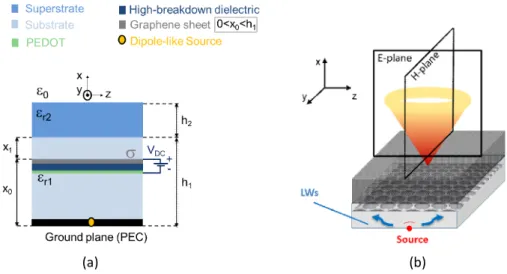
Figure 3. Graphene-based FPCA in a substrate-superstrate configuration. (a) Transverse view of the multilayer, including the graphene biasing scheme. (b) 3-D view of the conical pattern. More information can be found in [74]. ©2017 IEEE. Reprinted, with permission, from [74].
Figure 4. Radiation patterns in the principal planes for the Graphene-based FPCA in Figure 3: scanning process at a fixed frequency by varying the graphene chemical potential
µcvia voltage bias in (a) the H-plane and (b) the E-plane. More information can be found
in [74]. ©2017 IEEE. Reprinted, with permission, from [74].
2-D LWA operation since, as is well known, the conductivity of graphene can be tuned via electric-field effect by means of a suitable electrostatic bias. This has prompted in the last few years a number of investigations on different kinds of graphene reconfigurable antennas. Recently, examples of graphene-based reconfigurable 2-D LWAs have also appeared, operating in the THz range and based on patterned graphene HISs [77] or unpatterned graphene sheets above a grounded slab [78] or in a substrate-superstrate configuration [74, 79] (see the structure in Figure 3 and the relevant radiation patterns in the principal planes in Figure 4).
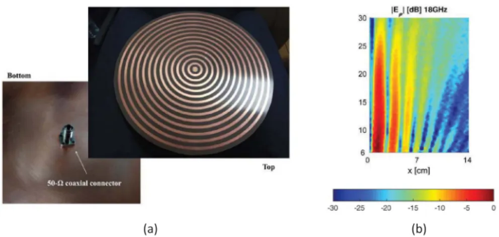
In addition to producing directive far-field patterns, FPCAs can also generate near-feld distri-butions with nondiffracting features, such as Bessel beams, exploiting the radiating features of backward cylindrical leaky waves [80,81], on the basis of the approach originally proposed in [82] and based on standing-wave aperture distributions. Bessel beams can also be produced using
Figure 5. (a) Bull-eye microstrip antenna for microwave Bessel-beam generation via back-ward cylindrical leaky waves. (b) Measured radial electric near field at f = 18 GHz in a lon-gitudinal plane, showing the desired Bessel-like pattern inside the non-diffracting range. More information can be found in [88]. ©2018 IEEE. Reprinted, with permission, from [88].
traveling-wave aperture distributions [83], which can be synthesized, e.g., through radial-line slot
antennas [84–86]. Alternatively, they can be synthesized by using 2-D LWAs not belonging to the class of FPCAs, based on radially periodic structures that cannot be homogenized (hence lack translational invariance) and support backward cylindrical leaky waves [87–89] (see Figure 5); similar structures also offer the possibility of focusing the radiation in the near field around a pre-scribed focal point [90,91]. These so-called “bull-eye” configurations were first proposed in [92] in the form of concentric microstrip rings for far-field operation in the microwave range; they were subsequently extensively studied by various groups, both at microwaves [93, 94] and, in variants based on metal corrugated structures, at millimeter-wave [95] and terahertz frequencies [96].
4. Holographic antennas
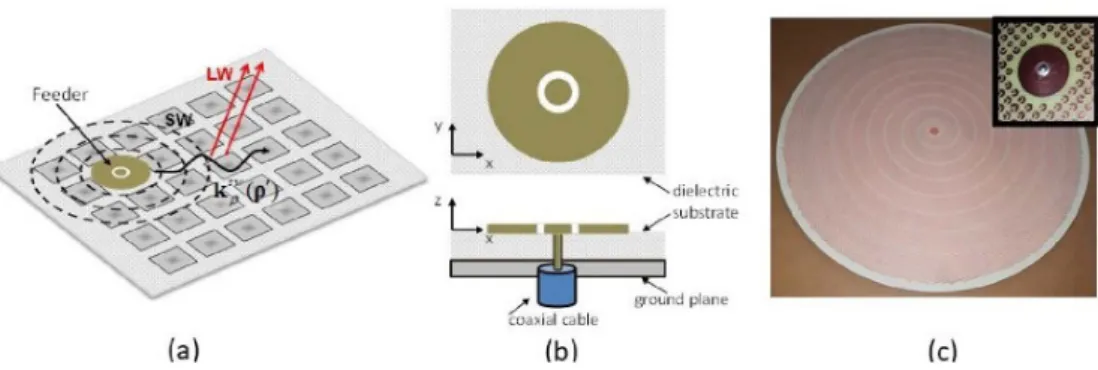
The present section reviews the research on using metasurfaces to transform guided waves into waves propagating in free space for the antenna design. This approach was firstly introduced by Sievenpiper’s group at the microwave regime using the holographic concept to design the impedance surfaces [97]. Then, this concept has been used and extended by several other groups adding more physical insight [98–108]. The general geometry is shown in Figure 6a. A planar feeder is illuminating a metasurface composed by subwavelength metallic elements printed over a grounded dielectric slab. If the metasurface is spatially homogenous the structure is able to support eigen guided modes (TM modes for the scalar case or hybrid TM–TE mode for the tensorial one) with propagation constant kswρ > k0. Since the spacing between adjacent elements
is subwavelength, it is possible, using a slow variation of the impedance, to modify the wavevector of a guided wave adiabatically. Some techniques have been developed in order to study the propagation of the SW on such inhomogeneous metasurfaces [102–104].
In the scalar case the design is addressed considering as local tangent problem a sinu-soidally modulated impedance of the form Z (x) = j Xs[1 + M cos(2πx/p)], where Xs represents
the average reactance value, p the period, and M < 1 is the modulation index. The field over the metasurface can be expressed as the sum of Floquet modes. However, as demonstrated in [98, 100, 108], to the first order with respect to the small parameter M , only 3 modes con-tribute significantly to the field. If kρsw−2π/p < k0one term radiates in free-space in the direction
Figure 6. (a) General geometry. A propagating SW is transformed into a LW via impedance modulation. (b) Coaxial Feeder geometry. (c) A metasurface antenna geometry working at 12 GHz designed at Sorbonne Université.
θ = arcsin((ksw
ρ −2π/p)/k0) with an amplitude proportional to M . The antenna is synthesized
us-ing an inhomogeneous modulation of the impedance (Figure 6c) obtained by varyus-ing the M and
p parameters of the modulation law. The entire metasurface is seen as an equivalent aperture
surface magnetic current distribution whose phase and amplitude depend on the local modula-tion parameters, while the direcmodula-tion is dictated by the source. Using standard aperture antenna theory is it possible to optimize the parameters to obtain the desired radiation pattern. However, the range of different aperture field distributions achievable is limited by the inability to control the direction of the equivalent aperture surface current [100]. The most commonly used incident wave in the literature is the cylindrical SW generated by a coaxial probe (Figure 6b) placed at the center of the metasurface (equivalent magnetic current oriented alongφ). Single beam cir-cularly polarized antennas have been developed and experimentally validated (Figure 6a) using a spiral dependance of the impedance for the broadside direction [98] while an elongated spiral distribution is needed for tilted beams [100]. Linearly polarized beams have been achieved using some azimuthal phase discontinuity [100,109] in order to compensate in the opposite direction of symmetric current elements with respect to the origin. Multiple modulations have been used to generate beams at different frequencies [110]. Scalar metasurfaces have been also used to design near-field antennas as a Bessel beam [100]. From the scalar nature of the metasurface follows that the TM and TE polarization of the field could be designed separately. This aspect has been used to design polarization-insensitive antennas [111], dual-circularly polarized antenna [112], polariza-tion reconfigurable antennas [113] and to generate different beams using multiple sources [114]. Tensorial metasurface antennas can be used to produce complex radiation patterns taking advantage of the ability to control the current orientation. Energy conservation and reciprocity imply that impedance tensor must be anti-Hermitian. Thus, physical impedances are described only by 3 real parameters. The antenna design is addressed considering as local tangent problem a modulated impedance tensor which elements have the form Zi(x) = j Xsi[1 + Micos(2πx/pi)],
where each component can have different period. As for the scalar case, the field above the metasurface can be seen as the sum of TM and TE Floquet modes. However, several terms now contribute to the radiated field as shown in [108]. In the first paper on the topic [97], the impedance tensor obtained from the holography principle was not anti-Hermitian, thus the impedance was synthesized using only the anti-Hermitian part of such tensor. This operation leads to non-sinusoidal modulations that can excite undesired radiating Floquet’s modes [108]. Later, a different approach was successfully introduced by another group [103], where the SW-field is considered as quasi-TM mode, thus the design is performed using two independent tensor parameters. A third approach based on a local holography principle was introduced in [104],
Figure 7. (a) Circularly polarized beam generated by a spiral scalar impedance metasur-face. ©2011 IEEE. Reprinted, with permission, from [122]. (b) Isoflux antenna generated by tensorial metasuface. ©2012 IEEE. Reprinted, with permission, from [118]. (c) Near-field shaping and confinement using tensorial metasurface. ©2019 IEEE. Reprinted, with per-mission, from [121].
where the whole impedance parameters were used in order to implement a general aperture field distribution. More recently, a numerical optimization method based on the electric field integral equation (EFIE) was successfully used in order to generate numerical results [115].
Single beam antennas have been experimentally validated in [116, 117] (Figure 7a). Numerical results of shaped beam configurations have been presented in [103]. More complex radiation pattern as isoflux [118] or flat-top [104] have been successfully designed (Figure 7b), while multi-beam configurations have been presented in [104, 119], and experimentally validated in [120]. In addition, the near-field shaping capability of tensorial metasurface has been experimentally demonstrated in [121] where the energy has been confined in 4 beams (Figure 7c).
5. Parallel plate metasurfaces for antennas
Often, metasurfaces are not directly used in radiation, but rather that to control the propagation of confined waves. Commonly, these metasurfaces are embbeded between parallel plates to avoid any leakage. Once the desired distributions of both phase and amplitude are tailored, it is possible to produce high performance antennas [123]. The unit cells inside of the parallel plate must be adequately designed and distributed in order to produce the required equivalent refractive indexes (isotropic or anisotropic) and impedances [124, 125] that produce the desired phase and amplitude at the end of the metasurface. This type of metasurfaces can be classified as metallic and dielectric.
5.1. Fully-metallic metasurfaces
Fully-metallic metasurfaces are used to produce low-loss electromagnetic devices that can han-dle high power. Dielectric losses are typically high in the millimetre bands, above 30 GHz. There-fore, for high-frequency applications, such as 5G, fully-metallic solutions are preferred [126]. Fully-metallic configurations are also desired in radar systems and defense applications, where the systems must typically handle elevated amount of power [127].
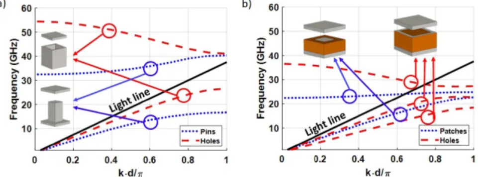
There are two main types of metallic-configurations: bed-of-nails [128, 129] and holey struc-tures [130]. These configurations are illustrated in Figure 8(a). Holey strucstruc-tures are more ro-bust and cost-effective than pins. However, pin-type metasurfaces can achieve higher equivalent refractive indexes, and they do not require of thin air-gaps between layers [131]. The dispersion properties of these two type of structures are illustrated Figure 8(a).
Figure 8. Dispersion diagrams of (a) pin-type and holey metallic metasurfaces, (b) patch-and holey-type dielectric metasurfaces.
5.2. Dielectric metasurfaces
For lower frequencies, dielectric metasurfaces are a preferred solution, since they are more cost-effective. Here again, there are two types of dielectric metasurfaces: patch- [132] and holey-type [133]. Patch-holey-type metasurfaces are quite independent of the height between parallel plates. However, holey-type metasurfaces require thin plate gaps to produce high refractive indexes [134]. In general, holey-type structures provide lower losses than patch-type, since the waves will propagate mainly in the air. These two configurations and their dispersion diagrams are illustrated in Figure 8(b).
5.3. Lens designs
All these configurations have employed to produce a number of lenses, such as the Maxwell fish-eye lens [135] and its generalized version [136]. However, the most popular lens for antenna designs is the Luneburg lens. A Luneburg lens antenna typically needs a transformation from parallel plate to free-space. There are two methods to produce an efficient radiation: leaky-waves [137] or flares [138].
Among these two, the most used technique is the flare, since leaky-waves are dispersive, meaning that the angle of radiation changes with the frequency [139]. In the case of patch-type metasurfaces, it is difficult to reduce the reflections at the end of the structure since most of the fields are confined in the dielectric slab [140]. This problem does not exist in fully-metallic structures [131] and dielectric holey-type [134]. However, in the case of holey-type structures (metallic or dielectric), the flare may be long to achieve low-level of reflections. This is due to the fact that the air-gap between the metasurface and the ground plane must thin to achieve the required equivalent refractive index [141].
5.4. Glide-symmetric metasurfaces
Glide symmetry is a new degree of freedom that has been recently proposed to improve the properties of metasurfaces, for example, to increase the bandwidth and attenuation of stopbands created by periodic structures [142–144]. One periodic structure possesses glide symmetry if it is invariant after a translation and a mirroring [145, 146]. By adding glide symmetry to a metasurface, it is possible to increase its bandwidth of operation, i.e. to reduce its dispersion [147]. Additionally, glide symmetry can be used to increase the equivalent refractive index of periodic structures [131, 141], their anisotropy [148] and their magnetic response [149]. These
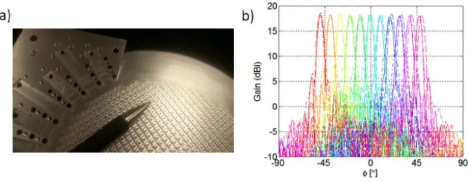
Figure 9. Glide-symmetric metasurface antenna in Ka-band: (a) Photo of the antenna, (b) Radiation patterns at 28 GHz. More information can be found in [141]. ©2018 IEEE. Reprinted, with permission, from [141].
features are beneficial to produce lens antennas. An example of a Luneburg lens antenna made of glide-symmetric metasurfaces is illustrated in Figure 9. This antenna operates in Ka-band and it designed for 5G communications. The antenna is able to produce a extreme angles of radiation with low scan-losses and high efficiency.
6. Conclusions
Metasurfaces have revolutionized the design of electromagnetic devices through tailoring sub-wavelength structures to shape the electromagnetic field. In this paper, we have reviewed the re-cent development in metasurface antenna design by introducing the fundamental concepts and presenting the actual state of the art of the physical realizations. Most of the presented examples operate at microwave but the same concept can be used up to visible light.
Starting from high impedance surface antennas, we have discussed how placing a planar an-tenna in the vicinity of a suitable metasurface could enhance its performances. We introduced how similar approaches could be used to improve the performances of Fabry–Perot cavity anten-nas and other 2-D leaky wave antenanten-nas. Furthermore, we discussed how the wave-front shap-ing ability of the metasurfaces can be used to design holographic aperture metasurface anten-nas (based on the conversion of a surface-wave into a radiated one) or to design planar lenses or control the dispersion properties in antenna structures.
With the level of advancements made already, there is a great prospect for the future. In re-cent years, research has been mainly conducted with the focus to improve the antenna perfor-mances using passive metasurfaces. Some active solutions have been presented (using control elements such as varactors, etc. . . ), leading to bulky and expensive devices (complexity and cost proportional to the number of unit cells). The challenge for the next years will be the develop-ment of low-cost fully tunable or reconfigurable metasurfaces. This aspect will dramatically im-prove both antenna and optical beam-forming applications and open up new possibilities for electromagnetic devices.
References
[1] O. Quevedo-Teruel, H. Chen, A. Díaz-Rubio, G. Gok, A. Grbic, G. Minatti, E. Martini, S. Maci, G. V. Eleftheriades, M. Chen, N. I. Zheludev, N. Papasimakis, S. Choudhury, Z. A. Kudyshev, S. Saha, H. Reddy, A. Boltasseva, V. M. Shalaev, A. V. Kildishev, D. Sievenpiper, C. Caloz, A. Alù, Q. He, L. Zhou, G. Valerio, E. Rajo-Iglesias, Z. Sipus, F. Mesa, R. Rodríguez-Berral, F. Medina, V. Asadchy, S. Tretyakov, C. Craeye, “Roadmap on metasurfaces”, J. Opt. 21 (2019), no. 7, article ID 073002.
[2] B. A. Munk, Frequency Selective Surfaces Theory and Design, Wiley Interscience, New York, 1995.
[3] N. Engheta, R. Ziolkowski, Electromagntic Metamaterials: Physics and Engineering Aspects, IEE-Wiley, New York, 2006.
[4] A. Patel, A. Grbic, “Effective surface impedance of a printed-circuit tensor impedance surface (pctis)”, IEEE Trans.
Microw. Theory Tech. 61 (2013), no. 4, p. 1403-1413.
[5] C. L. Holloway, E. F. Kuester, J. Gordon, J. O. Hara, J. Booth, D. R. Smith, “An overview of the theory and applications of metasurfaces: the two-dimensional equivalents metamaterials”, IEEE Trans. Antennas Propag. 54 (2012), no. 2, p. 10-35.
[6] A. Li, S. Singh, D. Sievenpiper, “Metasurfaces and their applications”, Nanophotonics 7 (2018), no. 6, p. 989-1011. [7] H. H. Hsiao, C. H. Chu, D. P. Tsai, “Fundamentals and applications of metasurfaces”, Small Methods 1 (2017), no. 4,
article ID 1600064.
[8] S. Gaber, S. H. Zainud-Deen, H. A. E. Malhat, Analysis and Design of Reflectarrays/Transmitarrays Antennas, Lambert Academic Publishing, Saarbrücken, 2014.
[9] D. Sievenpiper, L. Zhang, R. F. J. Broas, N. G. Alexopolous, E. Yablonovitch, “High-impedance electromagnetic surfaces with a forbidden frequency band”, IEEE Trans. Microw. Theory Tech. 47 (1999), no. 11, p. 2059-2074. [10] A. O. Bah, P. Qin, R. W. Ziolkowski, Y. J. Guo, T. S. Bird, “A wideband low-profile tightly coupled antenna array with a
very high figure of merit”, IEEE Trans. Antennas Propag. 67 (2019), no. 4, p. 2332-2343.
[11] F. Costa, O. Luukkonen, C. R. Simovski, A. Monorchio, S. A. Tretyakov, P. M. de Maagt, “TE surface wave resonances on high-impedance surface based antennas: analysis and modeling”, IEEE Trans. Antennas Propag. 59 (2011), no. 10, p. 3588-3596.
[12] F. Costa, S. Genovesi, A. Monorchio, “On the bandwidth of high-impedance frequency selective surfaces”, IEEE
Antennas Wirel. Propag. Lett. 8 (2009), p. 1341-1344.
[13] G. Valerio, D. R. Jackson, A. Galli, “Fundamental properties of surface waves in lossless stratified structures”, Proc.
R. Soc. A 466 (2010), no. 2120, p. 2447-2469.
[14] S. R. Best, D. L. Hanna, “Design of a broadband dipole in close proximity to an EBG ground plane”, IEEE Antennas
Propag. Mag. 50 (2008), no. 6, p. 52-64.
[15] G. Bianconi, F. Costa, S. Genovesi, A. Monorchio, “Optimal design of dipole antennas backed by a finite high-impedance screen”, Prog. Electromagn. Res. C 18 (2011), p. 137-151.
[16] H. Mosallaei, K. Sarabandi, “Antenna miniaturization and bandwidth enhancement using a reactive impedance substrate”, IEEE Trans. Antennas Propag. 52 (2004), no. 9, p. 2403-2414.
[17] F. Yang, Y. Rahmat-Samii, “Reflection phase characterizations of the EBG ground plane for low profile wire antenna applications”, IEEE Trans. Antennas Propag. 51 (2003), no. 10, p. 2691-2703.
[18] R. Coccioli, F.-R. Yang, K.-P. Ma, T. Itoh, “Aperture-coupled patch antenna on UC-PBG substrate”, IEEE Trans.
Microw. Theory Tech. 47 (1999), no. 11, p. 2123-2130.
[19] F. Yang, Y. Rahmat-Samii, “Microstrip antennas integrated with electromagnetic band-gap (EBG) structures: a low mutual coupling design for array applications”, IEEE Trans. Antennas Propag. 51 (2003), no. 10, p. 2936-2946. [20] R. F. J. Broas, D. F. Sievenpiper, E. Yablonovitch, “An application of high-impedance ground planes to phased array
antennas”, IEEE Trans. Antennas Propag. 53 (2005), no. 4, p. 1377-1381.
[21] M. Li, S. Xiao, B. Wang, “Investigation of using high impedance surfaces for wide-angle scanning arrays”, IEEE Trans.
Antennas Propag. 63 (2015), no. 7, p. 2895-2901.
[22] E. Rajo-Iglesias, O. Quevedo-Teruel, L. Inclan-Sanchez, “Planar soft surfaces and their application to mutual coupling reduction”, IEEE Trans. Antennas Propag. 57 (2009), no. 12, p. 3852-3859.
[23] F. Yang, Y. Rahmat-Samii, Electromagnetic Band Gap Structures in Antenna Engineering, Cambridge University Press, Cambridge, UK, 2009.
[24] Q. Zheng, Y. Fu, N. Yuan, “A novel compact spiral electromagnetic band-gap (EBG) structure”, IEEE Trans. Antennas
Propag. 56 (2008), no. 6, p. 1656-1660.
[25] M. F. Abedin, M. Z. Azad, M. Ali, “Wideband smaller unit-cell planar EBG structures and their application”, IEEE
Trans. Antennas Propag. 56 (2008), no. 3, p. 903-908.
[26] A. Vallecchi, J. R. De Luis, F. Capolino, F. De Flaviis, “Low profile fully planar folded dipole antenna on a high impedance surface”, IEEE Trans. Antennas Propag. 60 (2012), no. 1, p. 51-62.
[27] N. Engheta, R. W. Ziolkowski, “Innovation and intellectual property rights”, in Metamaterials: Physics and
Engineer-ing Explorations, Whiley, New York, USA, 2006, p. 377-402.
[28] P. Deo, A. Mehta, D. Mirshekar-Syahkal, P. J. Massey, H. Nakano, “Thickness reduction and performance enhance-ment of steerable square loop antenna using hybrid high impedance surface”, IEEE Trans. Antennas Propag. 58 (2010), no. 5, p. 1477-1485.
[29] N. Capet, C. Martel, J. Sokoloff, O. Pascal, “Optimum high impedance surface configuration for mutual coupling reduction in small antenna arrays”, Prog. Electromagn. Res. B 32 (2011), p. 283-297.
[30] J. Sarrazin, A. Lepage, X. Begaud, “Circular high-impedance surfaces characterization”, IEEE Antennas Wirel.
[31] M. A. Amiri, C. A. Balanis, C. R. Birtcher, “Analysis, design and measurements of circularly symmetric high-impedance surfaces for loop antenna applications”, IEEE Trans. Antennas Propag. 64 (2016), no. 2, p. 618-629. [32] M. A. Amiri, C. A. Balanis, C. R. Birtcher, “Gain and bandwidth enhancement of a spiral antenna using a circularly
symmetric HIS”, IEEE Antennas Wirel. Propag. Lett. 16 (2017), p. 1080-1083.
[33] A. Vallecchi, R. J. Langley, A. G. Schuchinsky, “Metasurfaces with interleaved conductors: phenomenology and applications to frequency selective and high impedance surfaces”, IEEE Trans. Antennas Propag. 64 (2016), no. 2, p. 599-608.
[34] A. Presse, A. Tarot, “Circuit model of a double-layer artificial magnetic conductor”, IEEE Antennas Wirel. Propag.
Lett. 15 (2016), p. 1061-1064.
[35] D. J. Kern, D. H. Werner, A. Monorchio, L. Lanuzza, M. J. Wilhelm, “The design synthesis of multiband artificial magnetic conductors using high impedance frequency selective surfaces”, IEEE Trans. Antennas Propag. 53 (2005), no. 1, p. 8-17.
[36] H.-H. Xie, Y.-C. Jiao, K. Song, Z. Zhang, “A novel multi-band electromagnetic band-gap structure”, Prog.
Electro-magn. Res. Lett. 9 (2009), p. 67-74.
[37] J. Sarrazin, A.-C. Lepage, X. Begaud, Z. Zhang, “Dual-band artificial magnetic conductor”, Appl. Phys. A 109 (2012), p. 1075-1080.
[38] D. Cure, T. M. Weller, F. A. Miranda, “Study of a low-profile 2.4-GHz planar dipole antenna using a high-impedance surface with 1-D varactor tuning”, IEEE Trans. Antennas Propag. 61 (2013), no. 2, p. 506-515.
[39] G. von Trentini, “Partially reflecting sheet arrays”, IRE Trans. Antennas Propag. 4 (1956), no. 4, p. 666-671. [40] A. P. Feresidis, J. Vardaxoglou, “High gain planar antenna using optimised partially reflective surfaces”, IEE
Proc.-Microw. Antennas Propag. 148 (2001), no. 6, p. 345-350.
[41] H. Boutayeb, K. Mahdjoubi, A.-C. Tarot, T. Denidni, “Directivity of an antenna embedded inside a Fabry–Perot cavity: analysis and design”, Microw. Opt. Technol. Lett. 48 (2006), no. 1, p. 12-17.
[42] A. Foroozesh, L. Shafai, “Investigation into the effects of the patch-type FSS superstrate on the high-gain cavity resonance antenna design”, IEEE Trans. Antennas Propag. 58 (2010), no. 2, p. 258-270.
[43] D. Jackson, N. Alexopoulos, “Gain enhancement methods for printed circuit antennas”, IEEE Trans. Antennas
Propag. 33 (1985), no. 9, p. 976-987.
[44] D. R. Jackson, A. A. Oliner, “A leaky-wave analysis of the high-gain printed antenna configuration”, IEEE Trans.
Antennas Propag. 36 (1988), no. 7, p. 905-910.
[45] T. Zhao, D. R. Jackson, J. T. Williams, H.-Y. Yang, A. A. Oliner, “2-d periodic leaky-wave antennas—Part I: metal patch design”, IEEE Trans. Antennas Propag. 53 (2005), no. 11, p. 3505-3514.
[46] T. Zhao, D. R. Jackson, J. T. Williams, “2-d periodic leaky-wave antennas—Part II: slot design”, IEEE Trans. Antennas
Propag. 53 (2005), no. 11, p. 3515-3524.
[47] T. Zhao, D. R. Jackson, J. T. Williams, A. A. Oliner, “General formulas for 2-D leaky-wave antennas”, IEEE Trans.
Antennas Propag. 53 (2005), no. 11, p. 3525-3533.
[48] G. Lovat, P. Burghignoli, D. R. Jackson, “Fundamental properties and optimization of broadside radiation from uniform leaky-wave antennas”, IEEE Trans. Antennas Propag. 54 (2006), no. 5, p. 1442-1452.
[49] A. Ip, D. R. Jackson, “Radiation from cylindrical leaky waves”, IEEE Trans. Antennas Propag. 38 (1990), no. 4, p. 482-488.
[50] S. Wang, A. Feresidis, G. Goussetis, J. Vardaxoglou, “Low-profile resonant cavity antenna with artificial magnetic conductor ground plane”, Electron. Lett. 40 (2004), no. 7, p. 405-406.
[51] A. P. Feresidis, G. Goussetis, S. Wang, J. C. Vardaxoglou, “Artificial magnetic conductor surfaces and their application to low-profile high-gain planar antennas”, IEEE Trans. Antennas Propag. 53 (2005), no. 1, p. 209-215.
[52] S. Wang, A. Feresidis, G. Goussetis, J. Vardaxoglou, “High-gain subwavelength resonant cavity antennas based on metamaterial ground planes”, IEE Proc.-Microw. Antennas Propag. 153 (2006), no. 1, p. 1-6.
[53] L. Zhou, H. Li, Y. Qin, Z. Wei, C. Chan, “Directive emissions from subwavelength metamaterial-based cavities”, Appl.
Phys. Lett. 86 (2005), no. 10, article ID 101101.
[54] A. Ourir, A. de Lustrac, J.-M. Lourtioz, “All-metamaterial-based subwavelength cavities (λ/60) for ultrathin directive antennas”, Appl. Phys. Lett. 88 (2006), no. 8, article ID 084103.
[55] A. Feresidis, J. Vardaxoglou, “A broadband high-gain resonant cavity antenna with single feed”, in 2006 First
European Conference on Antennas and Propagation, IEEE, 2006, p. 1-5.
[56] C. Mateo-Segura, A. P. Feresidis, G. Goussetis, “Bandwidth enhancement of 2-D leaky-wave antennas with double-layer periodic surfaces”, IEEE Trans. Antennas Propag. 62 (2014), no. 2, p. 586-593.
[57] K. Konstantinidis, A. P. Feresidis, P. S. Hall, “Multilayer partially reflective surfaces for broadband Fabry–Perot cavity antennas”, IEEE Trans. Antennas Propag. 62 (2014), no. 7, p. 3474-3481.
[58] L. Moustafa, B. Jecko, “Broadband high gain compact resonator antennas using combined FSS”, in 2008 IEEE
Antennas Propagation Society International Symposium, IEEE, San Diego, CA, USA, 2008, p. 1-4.
gradients to design, wideband, low-profile EBG resonator antennas”, IEEE Trans. Antennas Propag. 60 (2012), no. 2, p. 743-750.
[60] L. Moustafa, B. Jecko, “EBG structure with wide defect band for broadband cavity antenna applications”, IEEE
Antennas Wirel. Propag. Lett. 7 (2008), p. 693-696.
[61] R. M. Hashmi, B. A. Zeb, K. P. Esselle, “Wideband high-gain EBG resonator antennas with small footprints and all-dielectric superstructures”, IEEE Trans. Antennas Propag. 62 (2014), no. 6, p. 2970-2977.
[62] A. A. Baba, R. M. Hashmi, K. P. Esselle, A. R. Weily, “Compact high-gain antenna with simple all-dielectric partially reflecting surface”, IEEE Trans. Antennas Propag. 66 (2018), no. 8, p. 4343-4348.
[63] A. Hosseini, F. Capolino, D. R. Jackson, “Leaky-wave explanation of gain-bandwidth-enhanced Fabry–Perot cavity antennas formed by a thick multilayer partially-reflective surface”, in 2015 IEEE International Symposium on
Antennas Propagation & USNC/URSI National Radio Science Meeting, IEEE, Vancouver, BC, Canada, 2015, p.
1090-1091.
[64] A. T. Almutawa, A. Hosseini, D. R. Jackson, F. Capolino, “Leaky-wave analysis of wideband planar Fabry–Perot cavity antennas formed by a thick PRS”, IEEE Trans. Antennas Propag. 67 (2019), no. 8, p. 5163-5175.
[65] P. Burghignoli, G. Lovat, F. Capolino, D. R. Jackson, D. R. Wilton, “Highly polarized directive radiation from a Fabry– Pérot cavity leaky-wave antenna based on a metal strip grating”, IEEE Trans. Antennas Propag. 58 (2010), no. 12, p. 3873-3883.
[66] D. Comite, P. Baccarelli, P. Burghignoli, A. Galli, “Omnidirectional 2-D leaky-wave antennas with reconfigurable polarization”, IEEE Antennas Wirel. Propag. Lett. 16 (2017), p. 2354-2357.
[67] D. Sievenpiper, J. Schaffner, J. Lee, S. Livingston, “A steerable leaky-wave antenna using a tunable impedance ground plane”, IEEE Antennas Wirel. Propag. Lett. 1 (2002), p. 179-182.
[68] D. F. Sievenpiper, “Forward and backward leaky wave radiation with large effective aperture from an electronically tunable textured surface”, IEEE Trans. Antennas Propag. 53 (2005), no. 1, p. 236-247.
[69] A. Ourir, S. Burokur, A. de Lustrac, “Electronically reconfigurable metamaterial for compact directive cavity anten-nas”, Electron. Lett. 43 (2007), no. 13, p. 698-700.
[70] F. Costa, A. Monorchio, S. Talarico, F. M. Valeri, “An active high-impedance surface for low-profile tunable and steerable antennas”, IEEE Antennas Wirel. Propag. Lett. 7 (2008), p. 676-680.
[71] F. Costa, A. Monorchio, “Design of subwavelength tunable and steerable Fabry–Perot/leaky wave antennas”, Prog.
Electromagn. Res. 111 (2011), p. 467-481.
[72] R. Guzmán-Quirós, A. R. Weily, J. L. Gómez-Tornero, Y. J. Guo, “A Fabry–Pérot antenna with two-dimensional electronic beam scanning”, IEEE Trans. Antennas Propag. 64 (2016), no. 4, p. 1536-1541.
[73] A. R. Weily, T. S. Bird, Y. J. Guo, “A reconfigurable high-gain partially reflecting surface antenna”, IEEE Trans.
Antennas Propag. 56 (2008), no. 11, p. 3382-3390.
[74] W. Fuscaldo, P. Burghignoli, P. Baccarelli, A. Galli, “Graphene Fabry–Pérot cavity leaky-wave antennas: plasmonic versus nonplasmonic solutions”, IEEE Trans. Antennas Propag. 65 (2017), no. 4, p. 1651-1660.
[75] G. Lovat, P. Burghignoli, S. Celozzi, “A tunable ferroelectric antenna for fixed-frequency scanning applications”,
IEEE Antennas Wirel. Propag. Lett. 5 (2006), p. 353-356.
[76] W. Fuscaldo, S. Tofani, D. C. Zografopoulos, P. Baccarelli, P. Burghignoli, R. Beccherelli, A. Galli, “Tunable Fabry– Pérot cavity THz antenna based on leaky-wave propagation in nematic liquid crystals”, IEEE Antennas Wirel.
Propag. Lett. 16 (2017), p. 2046-2049.
[77] X.-C. Wang, W.-S. Zhao, J. Hu, W.-Y. Yin, “Reconfigurable terahertz leaky-wave antenna using graphene-based high-impedance surface”, IEEE Trans. Nanotechnol. 14 (2015), no. 1, p. 62-69.
[78] W. Fuscaldo, P. Burghignoli, P. Baccarelli, A. Galli, “Complex mode spectra of graphene-based planar structures for THz applications”, J. Infrared Millimeter Terahertz Waves 36 (2015), no. 8, p. 720-733.
[79] W. Fuscaldo, P. Burghignoli, P. Baccarelli, A. Galli, “A reconfigurable substrate–superstrate graphene-based leaky-wave THz antenna”, IEEE Antennas Wirel. Propag. Lett. 15 (2016), p. 1545-1548.
[80] M. Ettorre, A. Grbic, “Generation of propagating Bessel beams using leaky-wave modes”, IEEE Trans. Antennas
Propag. 60 (2012), no. 8, p. 3605-3613.
[81] W. Fuscaldo, G. Valerio, A. Galli, R. Sauleau, A. Grbic, M. Ettorre, “Higher-order leaky-mode Bessel-beam launcher”,
IEEE Trans. Antennas Propag. 64 (2016), no. 3, p. 904-913.
[82] S. Chávez-Cerda, “A new approach to Bessel beams”, J. Modern Opt. 46 (1999), no. 6, p. 923-930.
[83] M. Albani, S. Pavone, M. Casaletti, M. Ettorre, “Generation of non-diffractive Bessel beams by inward cylindrical traveling wave aperture distributions”, Opt. Express 22 (2014), no. 15, p. 18354-18364.
[84] A. Mazzinghi, M. Balma, D. Devona, G. Guarnieri, G. Mauriello, M. Albani, A. Freni, “Large depth of field pseudo– Bessel beam generation with a RLSA antenna”, IEEE Trans. Antennas Propag. 62 (2014), no. 8, p. 3911-3919. [85] M. Ettorre, S. C. Pavone, M. Casaletti, M. Albani, “Experimental validation of Bessel beam generation using an
inward Hankel aperture distribution”, IEEE Trans. Antennas Propag. 63 (2015), no. 6, p. 2539-2544.
[86] S. Pavone, M. Ettorre, M. Casaletti, M. Albani, “Transverse circular-polarized bessel beam generation by inward cylindrical aperture distribution”, Opt. Express 24 (2016), no. 10, p. 11103-11111.
[87] B. G. Cai, Y. B. Li, W. X. Jiang, Q. Cheng, T. J. Cui, “Generation of spatial Bessel beams using holographic metasur-face”, Opt. Express 23 (2015), no. 6, p. 7593-7601.
[88] D. Comite, W. Fuscaldo, S. K. Podilchak, P. D. Hílario-Re, V. Gómez-Guillamón Buendía, P. Burghignoli, P. Baccarelli, A. Galli, “Radially periodic leaky-wave antenna for Bessel beam generation over a wide-frequency range”, IEEE
Trans. Antennas Propag. 66 (2018), no. 6, p. 2828-2843.
[89] W. Fuscaldo, D. Comite, A. Boesso, P. Baccarelli, P. Burghignoli, A. Galli, “Focusing leaky waves: a class of electro-magnetic localized waves with complex spectra”, Phys. Rev. A 9 (2018), no. 5, article ID 054005.
[90] J. L. Gómez-Tornero, D. Blanco, E. Rajo-Iglesias, N. Llombart, “Holographic surface leaky-wave lenses with circularly-polarized focused near-fields—Part I: concept, design and analysis theory”, IEEE Trans. Antennas Propag.
61 (2013), no. 7, p. 3475-3485.
[91] D. Blanco, J. L. Gómez-Tornero, E. Rajo-Iglesias, N. Llombart, “Holographic surface leaky-wave lenses with circularly-polarized focused near-fields—Part II: experiments and description of frequency steering of focal length”, IEEE Trans. Antennas Propag. 61 (2013), no. 7, p. 3486-3494.
[92] P. Baccarelli, P. Burghignoli, G. Lovat, S. Paulotto, “A novel printed leaky-wave ‘bull-eye’ antenna with suppressed surface-wave excitation”, in IEEE Antennas Propagation Society Symposium, vol. 1, IEEE, Monterey, CA, USA, 2004, p. 1078-1081.
[93] S. Podilchak, Y. Antar, A. Freundorfer, P. Baccarelli, P. Burghignoli, S. Paulotto, G. Lovat, “Planar antenna for continuous beam scanning and broadside radiation by selective surface wave suppression”, Electron. Lett. 46 (2010), no. 9, p. 613-614.
[94] S. K. Podilchak, P. Baccarelli, P. Burghignoli, A. P. Freundorfer, Y. M. Antar, “Analysis and design of annular microstrip-based planar periodic leaky-wave antennas”, IEEE Trans. Antennas Propag. 62 (2014), no. 6, p. 2978-2991.
[95] U. Beaskoetxea, V. Pacheco-Peña, B. Orazbayev, T. Akalin, S. Maci, M. Navarro-Cía, M. Beruete, “77-GHz high-gain bull’s-eye antenna with sinusoidal profile”, IEEE Antennas Wirel. Propag. Lett. 14 (2015), p. 205-208.
[96] M. Beruete, U. Beaskoetxea, M. Zehar, A. Agrawal, S. Liu, K. Blary, A. Chahadih, X.-L. Han, M. Navarro-Cía, D. E. Salinas et al., “Terahertz corrugated and bull’s-eye antennas”, IEEE Trans. Terahertz Science and Technol. 3 (2013), no. 6, p. 740-747.
[97] B. H. Fong, J. S. Colburn, J. J. Ottusch, J. L. Visher, D. F. Sievenpiper, “Scalar and tensor holographic artificial impedance surfaces”, IEEE Trans. Antennas Propag. 58 (2010), no. 10, p. 3212-3221.
[98] G. Minatti, F. Caminita, M. Casaletti, S. Maci, “Spiral leaky-wave antennas based on modulated surface impedance”,
IEEE Trans. Antennas Propag. 59 (2011), no. 12, p. 4436-4444.
[99] A. M. Patel, A. Grbic, “A printed leaky-wave antenna based on a sinusoidally-modulated reactance surface”, IEEE
Trans. Antennas Propag. 59 (2011), no. 6, p. 2087-2096.
[100] M. Casaletti, M. ´Smierzchalski, M. Ettorre, R. Sauleau, N. Capet, “Polarized beams using scalar metasurfaces”, IEEE
Trans. Antennas Propag. 64 (2016), no. 8, p. 3391-3400.
[101] A. M. Patel, A. Grbic, “The effects of spatial dispersion on power flow along a printed-circuit tensor impedance surface”, IEEE Trans. Antennas Propag. 62 (2014), no. 3, p. 1464-1469.
[102] E. Martini, M. Mencagli, D. Gonzalez-Ovejero, S. Maci, “Flat optics for surface waves”, IEEE Trans. Antennas Propag.
64 (2016), no. 1, p. 155-166.
[103] G. Minatti, F. Caminita, E. Martini, M. Sabbadini, S. Maci, “Synthesis of modulated-metasurface antennas with amplitude phase and polarization control”, IEEE Trans. Antennas Propag. 64 (2016), no. 9, p. 3907-3919.
[104] M. Teniou, H. Roussel, N. Capet, G. Piau, M. Casaletti, “Implementation of radiating aperture field distribution using tensorial metasurfaces”, IEEE Trans. Antennas Propag. 65 (2017), no. 11, p. 5895-5907.
[105] G. Minatti, F. Caminita, E. Martini, S. Maci, “Flat optics for leaky-waves on modulated metasurfaces: adiabatic floquet-wave analysis”, IEEE Trans. Antennas Propag. 64 (2016), no. 9, p. 3896-3906.
[106] G. Minatti, E. Martini, S. Maci, “Efficiency of metasurface antennas”, IEEE Trans. Antennas Propag. 65 (2017), no. 4, p. 1532-1541.
[107] G. Minatti, M. Faenzi, M. Sabbadini, S. Maci, “Bandwidth of gain in metasurface antennas”, IEEE Trans. Antennas
Propag. 65 (2017), no. 6, p. 2836-2842.
[108] M. Casaletti, “Guided waves on scalar and tensorial reactance surfaces modulated by periodic functions: a circuital approach”, IEEE Access 7 (2019), p. 68823-68836.
[109] S. Pandi, C. A. Balanis, C. R. Birtcher, “Design of scalar impedance holographic metasurfaces for antenna beam formation with desired polarization”, IEEE Trans. Antennas Propag. 63 (2015), no. 7, p. 3016-3024.
[110] Y. Li, A. Li, T. Cui, D. F. Sievenpiper, “Multiwavelength multiplexing hologram designed using impedance metasur-faces”, IEEE Trans. Antennas Propag. 66 (2018), no. 11, p. 6408-6413.
[111] M. Li, S. Xiao, D. F. Sievenpiper, “Polarization-insensitive holographic surfaces with broadside radiation”, IEEE
Trans. Antennas Propag. 64 (2016), no. 12, p. 5272-5280.
of a Ku-band dual-circularly polarized metasurface antenna”, IEEE Trans. Antennas Propag. 66 (2018), no. 3, p. 1153-1159.
[113] M. Li, M. Tang, S. Xiao, “Design of a LP, RHCP and LHCP polarization-reconfigurable holographic antenna”, IEEE
Access 7 (2019), p. 82776-82784.
[114] S. Ramalingam, C. A. Balanis, C. R. Birtcher, H. N. Shaman, “Polarization-diverse holographic metasurfaces”, IEEE
Antennas Wirel. Propag. Lett. 18 (2019), no. 2, p. 264-268.
[115] M. Bodehou, C. Craeye, E. Martini, I. Huynen, “A quasi-direct method for the surface impedance design of modulated metasurface antennas”, IEEE Trans. Antennas Propag. 67 (2019), no. 1, p. 24-36.
[116] M. Faenzi, F. Caminita, E. Martini, P. De Vita, G. Minatti, M. Sabbadini, S. Maci, “Realization and measurement of broadside beam modulated metasurface antennas”, IEEE Antennas Wirel. Propag. Lett. 15 (2016), p. 610-613. [117] M. Teniou, H. Roussel, M. Serhir, N. Capet, G.-P. Piau, M. Casaletti, “Tensorial metasurface antennas radiating
polarized beams based on aperture field implementation”, Int. J. Microw. Wirel. Technol. 10 (2018), no. 2, p. 161-168. [118] G. Minatti, S. Maci, P. De Vita, A. Freni, M. Sabbadini, “A circularly-polarized isoflux antenna based on anisotropic
metasurface”, IEEE Trans. Antennas Propag. 60 (2012), no. 11, p. 4998-5009.
[119] D. Gonzalez-Ovejero, G. Minatti, G. Chattopadhyay, S. Maci, “Multibeam by metasurface antennas”, IEEE Trans.
Antennas Propag. 65 (2017), no. 6, p. 2923-2930.
[120] M. Teniou, H. Roussel, M. Serhir, N. Capet, G. Piau, M. Casaletti, “Experimental validation of tensorial metasurfaces for the implementation of radiating aperture field distributions”, IEEE Trans. Antennas Propag. 67 (2019), no. 7, p. 4901-4906.
[121] I. Iliopoulos, M. Teniou, M. Casaletti, P. Potier, P. Pouliguen, R. Sauleau, M. Ettorre, “Near-field multi-beam genera-tion by tensorial metasurfaces”, IEEE Trans. Antennas Propag. 67 (2019), no. 9, p. 6068-6075.
[122] S. Maci, G. Minatti, M. Casaletti, M. Bosiljevac, “Metasurfing: addressing waves on impenetrable metasurfaces”,
IEEE Antennas Wirel. Propag. Lett. 10 (2011), p. 1499-1502.
[123] G. Peeler, D. Archer, “A two-dimensional microwave Luneberg lens”, Trans. IRE Professional Group on Antennas
Propag. 1 (1953), no. 1, p. 12-23.
[124] K. Sato, H. Ujiie, “A plate Luneberg lens with the permittivity distribution controlled by hole density”, Electron.
Commun. Jpn. (Part I: Communications) 85 (2002), no. 9, p. 1-12.
[125] L. Xue, V. F. Fusco, “24 ghz automotive radar planar Luneburg lens”, IET Microw. Antennas Propag. 1 (2007), no. 3, p. 624-628.
[126] O. Quevedo-Teruel, M. Ebrahimpouri, F. Ghasemifard, “Lens antennas for 5G communications systems”, IEEE
Commun. Mag. 56 (2018), no. 7, p. 36-41.
[127] R. F. Rinehart, “A solution of the problem of rapid scanning for radar antennae”, J. Appl. Phys. 19 (1948), no. 9, p. 860-862.
[128] M. G. Silveirinha, C. A. Fernandes, J. R. Costa, “Electromagnetic characterization of textured surfaces formed by metallic pins”, IEEE Trans. Antennas Propag. 56 (2008), no. 2, p. 405-415.
[129] Y.-J. Park, W. Wiesbeck, “Angular independency of a parallel-plate luneburg lens with hexagonal lattice and circular metal posts”, IEEE Antennas Wirel. Propag. Lett. 1 (2002), p. 128-130.
[130] C. Walter, “Surface-wave Luneberg lens antennas”, IRE Trans. Antennas Propag. 8 (1960), no. 5, p. 508-515. [131] O. Quevedo-Teruel, M. Ebrahimpouri, M. Ng Mou Kehn, “Ultrawideband metasurface lenses based on off-shifted
opposite layers”, IEEE Antennas Wirel. Propag. Lett. 15 (2016), p. 484-487.
[132] O. Luukkonen, C. Simovski, G. Granet, G. Goussetis, D. Lioubtchenko, A. V. Raisanen, S. A. Tretyakov, “Simple and accurate analytical model of planar grids and high-impedance surfaces comprising metal strips or patches”, IEEE
Trans. Antennas Propag. 56 (2008), no. 6, p. 1624-1632.
[133] L. Xue, V. F. Fusco, “Printed holey plate Luneburg lens”, Microw. Opt. Technol. Lett. 50 (2008), no. 2, p. 378-380. [134] C. D. Diallo, O. Quevedo-Teruel, G. Valerio, H. Legay, R. Sauleau, “Parallel-plate-waveguide Luneburg lens through
a holey plate metasurface”, in 2015 9th European Conference on Antennas Propagation (EuCAP), IEEE, 2015, p. 1-2. [135] S. Maci, G. Minatti, M. Casaletti, M. Bosiljevac, “Metasurfing: addressing waves on impenetrable metasurfaces”,
IEEE Antennas Wirel. Propag. Lett. 10 (2011), p. 1499-1502.
[136] D. R. Prado, A. V. Osipov, O. Quevedo-Teruel, “Implementation of transformed lenses in bed of nails reducing refractive index maximum value and sub-unity regions”, Opt. Lett. 40 (2015), no. 6, p. 926-929.
[137] M. Ettorre, R. Sauleau, L. Le Coq, “Multi-beam multi-layer leaky-wave SIW pillbox antenna for millimeter-wave applications”, IEEE Trans. Antennas Propag. 59 (2011), no. 4, p. 1093-1100.
[138] C. Pfeiffer, A. Grbic, A. printed, “broadband Luneburg lens antenna”, IEEE Trans. Antennas Propag. 58 (2010), no. 9, p. 3055-3059.
[139] L. Wang, J. L. Gomez-Tornero, E. Rajo-Iglesias, O. Quevedo-Teruel, “Low-dispersive leaky-wave antenna integrated in groove gap waveguide technology”, IEEE Trans. Antennas Propag. 66 (2018), no. 11, p. 5727-5736.
[140] M. Bosiljevac, M. Casaletti, F. Caminita, Z. Sipus, S. Maci, “Non-uniform metasurface Luneburg lens antenna design”, IEEE Trans. Antennas Propag. 60 (2012), no. 9, p. 4065-4073.
metallic Luneburg lens for 5G communications at Ka-band”, IEEE Antennas Wirel. Propag. Lett. 17 (2018), no. 9, p. 1588-1592.
[142] M. Ebrahimpouri, E. Rajo-Iglesias, Z. Sipus, O. Quevedo-Teruel, “Cost-effective gap waveguide technology based on glide-symmetric holey EBG structures”, IEEE Trans. Microw. Theory Tech. 66 (2018), no. 2, p. 927-934.
[143] M. Ebrahimpouri, A. Algaba Brazalez, L. Manholm, O. Quevedo-Teruel, “Using glide-symmetric holes to reduce leakage between waveguide flanges”, IEEE Microw. Wirel. Components Lett. 28 (2018), no. 6, p. 473-475.
[144] A. Monje-Real, N. J. G. Fonseca, O. Zetterstrom, E. Pucci, O. Quevedo-Teruel, “Holey glide-symmetric filters for 5G at millimeter-wave frequencies”, IEEE Microw. Wirel. Components Lett. 30 (2020), no. 1, p. 31-34.
[145] G. Valerio, F. Ghasemifard, Z. Sipus, O. Quevedo-Teruel, “Glide-symmetric all-metal holey metasurfaces for low-dispersive artificial materials: modeling and properties”, IEEE Trans. Microw. Theory Tech. 66 (2018), no. 7, p. 3210-3223.
[146] F. Ghasemifard, M. Norgren, O. Quevedo-Teruel, G. Valerio, “Analyzing glide-symmetric holey metasurfaces using a generalized Floquet theorem”, IEEE Access 6 (2018), p. 71743-71750.
[147] M. Camacho, R. C. Mitchell-Thomas, A. P. Hibbins, J. R. Sambles, O. Quevedo-Teruel, “Mimicking glide symmetry dispersion with coupled slot metasurfaces”, Appl. Phys. Lett. 111 (2017), no. 12, article ID 121603.
[148] M. Ebrahimpouri, O. Quevedo-Teruel, “Ultrawideband anisotropic glide-symmetric metasurfaces”, IEEE Antennas
Wirel. Propag. Lett. 18 (2019), no. 8, p. 1547-1551.
[149] M. Ebrahimpouri, L. F. Herran, O. Quevedo-Teruel, “Wide-angle impedance matching using glide-symmetric metasurfaces”, IEEE Microw. Wirel. Compon. Lett. 30 (2020), no. 1, p. 8-11.
![Figure 1. AMC based on a 2-D array of metallic patches with vertical vias proposed in [9].](https://thumb-eu.123doks.com/thumbv2/123doknet/14678458.558655/5.816.171.654.113.310/figure-amc-based-array-metallic-patches-vertical-proposed.webp)