HAL Id: hal-00836942
https://hal-polytechnique.archives-ouvertes.fr/hal-00836942
Submitted on 19 May 2014
HAL is a multi-disciplinary open access
archive for the deposit and dissemination of
sci-entific research documents, whether they are
pub-lished or not. The documents may come from
teaching and research institutions in France or
abroad, or from public or private research centers.
L’archive ouverte pluridisciplinaire HAL, est
destinée au dépôt et à la diffusion de documents
scientifiques de niveau recherche, publiés ou non,
émanant des établissements d’enseignement et de
recherche français ou étrangers, des laboratoires
publics ou privés.
Shadowgraphic imaging of carbon nanotube suspensions
in water and in chloroform
L. Vivien, J. Moreau, D. Riehl, P.A. Alloncle, M. Autric, François Hache, E.
Anglaret
To cite this version:
L. Vivien, J. Moreau, D. Riehl, P.A. Alloncle, M. Autric, et al.. Shadowgraphic imaging of carbon
nanotube suspensions in water and in chloroform. Journal of the Optical Society of America B, Optical
Society of America, 2002, 19 (11), pp.2665. �10.1364/JOSAB.19.002665�. �hal-00836942�
Shadowgraphic imaging of carbon nanotube
suspensions in water and in chloroform
L. Vivien, J. Moreau, and D. Riehl
De´le´gation Ge´ne´rale pour l’Armement, Centre Technique d’Arcueil, Department Laser, Optique et Thermo-Optique, Arcueil, France
P. A. Alloncle and M. Autric
Institut de Recherche sur les Phenomenes Hors Equilibre, Marseille, France
F. Hache
Laboratoire d’Optique et Biosciences, Unite´ Mixte de Recherche, Centre National de la Recherche Scientifique 7645, Ecole Polytechnique, Palaiseau, France
E. Anglaret
Groupe de Dynamique des Phases Condense´es, Unite´ Mixte de Recherche, Centre National de la Recherche Scientifique 5581, Universite´ de Montpellier II, Montpellier, France
Received February 13, 2002; revised manuscript received June 14, 2002
Carbon nanotube suspensions are known to display interesting optical limiting properties as a result of the formation of solvent or carbon-vapor bubbles that scatter the laser beam. In this study we present an original experiment that permits direct observation of the changes that occur in the focal zone in carbon nanotube sus-pensions by using a shadowgraphic experiment coupled with a monochromatic pump–probe experiment. We have observed a clear correlation between the radius of the scattering centers and the evolution in transmit-tance of the sample. We compared bubble growth in chloroform and water and found good agreement with previously obtained results. We also observed the presence of compression waves, which propagate parallel to the laser beam and can produce secondary cavitation phenomena after reflection on the cell walls. © 2002 Optical Society of America
OCIS codes: 190.3970, 190.4400, 190.4870, 290.5850.
1. INTRODUCTION
The proliferation of lasers and systems that employ lasers has brought with it the danger of adverse effects from these bright, coherent light sources. These effects in-clude the possibility of damage from pulsed lasers as well as of temporary blinding by continuous-wave lasers. With nearly every possible wavelength being emitted by these sources, there exists a need to develop optical lim-iters and tunable filters that can suppress undesired ra-diation at any wavelength. Nowadays, laser sources (op-tical parametric oscillators, dye lasers, Raman lasers,...) are widely used in many applications, not only in research laboratories but also in large areas of industry and medi-cine and for military applications, and they pose a poten-tial hazard to eyes and other optical sensors (CCDs, ther-mal cameras, ...). These developments have motivated extensive research activity to design optical limiting sys-tems for eye and sensor protection.1,2 An ideal optical
limiter is a device for which, at low input fluence, the lin-ear transmittance is high (.70%), whereas, at high input fluence, the output energy is below the damage threshold of sensors or eyes. The device’s damage threshold must be high, as must be the limiting threshold. Nonlinear op-tical limiters may protect opop-tical sensors or eyes against
pulsed lasers of any wavelength (from visible to infrared radiation) and pulse durations (from a few picoseconds to continuous waves). To this end, all existing nonlinear materials require a tightly focused beam for initiating the effect and must therefore be incorporated into optical sys-tems. Several nonlinear effects have been proposed: nonlinear absorption (reverse saturable absorption,3 mul-tiphoton absorption), nonlinear refraction (electronics4or thermal effects5), and nonlinear scattering (solvent
bubble formation, or particle sublimation, or both6–8 or mismatched indices9). All these processes exhibit optical limiting behavior with advantages and disadvantages.
To achieve optical limiting we used carbon nanotubes suspended in water and in chloroform. In previous studies,10–13some of the present authors and others de-termined that the optical limiting effect in these materi-als originates in the growth of scattering centers as a re-sult of two physical mechanisms: The first one is thermal transfer from the particles to the surrounding liquid, and the second is sublimation of the carbon nano-tubes, which lead to solvent and carbon-vapor bubble growth, respectively. These gaseous cavities scatter the laser beam, leading to a drop in the sample transmit-tance. Carbon nanotube suspensions demonstrate good
efficiency for wavelengths from 400 to 1100 nm for pulse widths from 3 to 100 ns (Ref. 12) and possibly for pulse widths up to several microseconds.14 In addition, we
have been able to measure the average radius and the concentration of scattering centers by carrying out a poly-chromatic pump–probe experiment and using a theoreti-cal model that couples the Beer–Lambert law and Mie theory.13 These experiments have shown that nonlinear
scattering is due to many small vapor bubbles in chloro-form and to a small number of large vapor bubbles in wa-ter suspensions. We also observed a stronger coalescence in water than in chloroform. Measuring the evolution of scattering centers and the vapor bubble distribution dur-ing and after the pump pulse, we observed a coalescence effect13and a cavitation phenomenon in the microsecond regime.10 In this paper we present new results that we
obtained with a shadowgraphic experiment. This experi-ment consists in the direct photography of scattering cen-ters by means of an ultrarapid camera coupled with a
tra-ditional pump–probe experiment. This kind of
experiment has been widely used to illustrate plasma, bubble, and shock-wave formations that results from laser-induced breakdown in aqueous media.15 Goedert
et al.adapted this experiment for optical limiters includ-ing nonlinear scatterinclud-ing materials.16 We have also used
the technique to gain a better understanding of vapor bubble growth and have added a pump–probe experiment to measure the transmittance perturbation simulta-neously.
In Section 2 we present a synthesis method and a pu-rification procedure for single-wall carbon nanotubes. The shadowgraphic and pump–probe experimental setup is described in Section 3. In Section 4 we report the re-sults obtained 150 ns to 11 ms after the pump pulse in car-bon nanotube suspensions in chloroform. We compare the evolution of the probe transmittance and the scatter-ing centers in these suspensions. We also compare the difference between chloroform and water suspensions to confirm the results obtained in a previous study of the wavelength dependence of scattering efficiency.13 Among
the various mechanisms for the nonlinear scattering in carbon black and carbon nanotube suspensions, the for-mation of a microplasma has sometimes been proposed. In this study we determine the input energy for which plasma is formed in the focal zone; we have been able to determine the effect that is responsible for the optical lim-iting properties in carbon nanotube suspensions. Fi-nally, in Section 5 we present results obtained with an in-tensified CCD camera in which we observed the kinetics of vapor bubble growth from 5 to 150 ns after the maxi-mum of the pump pulse.
2. CARBON NANOTUBE SUSPENSIONS
Carbon nanotubes were synthesized by the electric arc discharge technique.17 An electric arc discharge is
cre-ated between two graphite electrodes in a helium atmo-sphere in the presence of a metallic catalyst (Ni and Y at 4.2:1 at. %) for the synthesis of single-wall carbon nano-tubes (SWNTs). As-prepared samples contain impurities such as amorphous carbon, graphite, fullerenes, and re-sidual catalysts. The SWNT samples are purified in a
three-step procedure.18 The first step uses a nitric acid
treatment at 100 °C that partially disintegrates the cata-lyst particles and disentangles the complex network of nanotubes, other carbonous materials, and catalyst par-ticles. The second step is a tangential filtration that al-lows the nanotubes to be separated from the other spe-cies. Finally, a thermal treatment in an inert atmosphere eliminates residual catalysts. After such pu-rification, the amount of SWNT is close to 90 vol. % in the samples. SWNTs usually self-assemble on a triangular array into crystalline nanobundles of a couple to some tens of tubes.19 The tubes are 1.3–1.5 nm in
diameter17,19and are several micrometers long. Single-wall carbon nanotube suspensions in water and in chloro-form are tested in 2-mm 3 2-mm square cells. The lin-ear transmittance is larger than 70% at 532 nm. The water (chloroform) suspensions are stable without any stirring for 6 (1) months.
3. EXPERIMENTAL SETUP
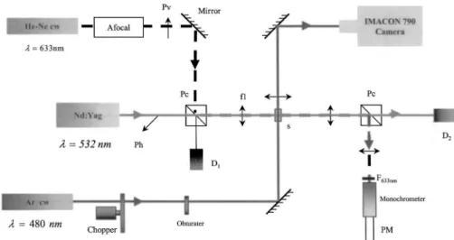
The aim of the experiment is to associate shadowgraphic illustration with a pump–probe experiment to connect the evolution of the gaseous cavities created by the pump la-ser in a carbon nanotube suspension with the change of transmittance of the probe. Figure 1 presents the experi-mental setup. The pump beam is directly obtained from a horizontally polarized Nd:YAG laser delivering 13-ns FWHM pulses at 532 or 1064 nm. To eliminate the cu-mulative effect we use this laser in single-shot mode. This monochromatic pump–probe configuration is similar to one used previously.10 The input energy is recorded with a pyroelectric detector, and the temporal profile is re-corded with a fast Si sensor. The pump beam passes through a polarizing cube to preserve horizontal polariza-tion and is focused into the sample with a 200-mm focal-length achromatic doublet (;f/20 focusing geometry). The sample is probed at 633 nm by a continuous He–Ne laser beam that is vertically polarized to permit separa-tion from the pump beam by a polarizing cube. The pump beam’s waist into the sample is 20 and 50mm at 532 and 1064 nm, respectively. The experimental configura-tion is chosen such that the probe’s waist is always smaller than that of the pump.
To this pump–probe experiment we add a second probe beam delivered by an argon-ion laser at 488 nm that illu-minates the carbon nanotube sample at 90° to the pump’s optical axis. With a 100-mm focal-length lens we image the focal zone of the pump onto a camera. The bubble dy-namics is investigated with a high-speed Imacon 790 (Hadland) camera. This camera permits framing rates of 104 to 2 3 107 frames/s and streak velocities from 10
ms/mm to 1 ns/mm. The first acquisition takes place ;150 ns after the pump pulse. Thus we could not see the primary events described in Ref. 10, but we clearly ob-served cavitation phenomena, as previously obob-served in
monochromatic and polychromatic pump–probe
experiments.10,13 We can be more quantitative and com-pare the evolution of the probe transmittance and the va-por bubble radii measured in the shadowgraphic imaging. To determine the kinetics of gaseous cavities we also use an intensified CCD camera which permits the
evolu-tion of scattering centers to be observed on a nanosecond time scale (from 5 to 150 ns). We determine the evolu-tion of vapor bubbles in the focal zone for times as short as 5 ns, i.e., during the pump pulses at 1064 nm. This experiment is complementary to the experiment de-scribed above. Both experiments make it possible to fol-low the evolution of the bubbles from the first moments to 11 ms after they begin to form.
4. MICROSECOND TIME-SCALE RESULTS
A. Time Evolution
In the first study we measure with the Imacon camera the evolution of scattering centers in carbon nanotube sus-pensions. We observe cavitation phenomena, and we compare the evolution of the probe transmittance and of the bubble radius. Figure 2 shows the temporal evolu-tion of scattering centers for carbon nanotube suspen-sions in chloroform for an input fluence of 9 J/cm2at 532 nm. Twenty-two images were acquired every 500 ns, and the first was saved 150 ns after the pump pulse. Each image scans an area of 425 mm 3 375 mm, corresponding to a quarter of the cell thickness. Simultaneously, we measure the probe perturbation with the pump–probe ex-periment. A cloud of small vapor bubbles is observed in the focal zone created by interaction between the laser beam and the suspensions. The peripheral bubbles are visible and seem homogeneous. The central part of the bubble cloud is not resolved by our imaging system. We observe a gradual diminution of the bubble cloud, and the small gaseous cavities located on the periphery of the cloud disappear rapidly, leading to a strong concentration of vapor bubbles in the central zone. Then the bubble cloud decreases gradually until it appears as shown in the photo numbered 16, where it experiences a new expan-sion phase that corresponds to a cavitation rebound. From these pictures we can conclude that, in chloroform, cavitation is not produced by a single macroscopic bubble but is due to the oscillation in phase of microscopic bubbles, giving rise to a collective effect.
In each image of Fig. 2 we measure the transversal semisection of the bubble cloud, which can be associated with an effective radius of scattering centers. Figure 3 presents the kinetics of this effective radius and the probe transmittance. The evolutions of the effective radius and of the probe transmittance are similar. The radius rap-idly reaches 60 mm and then collapses in 9 ms to a mini-mum of 5 mm before rebounding to 20 mm at the first re-bound. Concomitantly, the initial transmittance drop is followed by a partial recovery when the radius is mini-mum and by a further drop when the radius increases. The similarity between the two curves is striking, con-firming clearly the role of the laser-induced gaseous cavi-ties in the scattering process. Considering now the de-crease in bubble radius after the first microsecond, we can understand it as a competition between bubble expansion and the pressure effect of the surrounding solvent. Some of the present authors have already performed such a study by implementing an analysis based on the Rayleigh–Plesset model.10,11 Here we get a nice confir-mation of that study: Indeed, considering the experi-mental rebound time of 8 ms (see Fig. 3), the model
indi-cates that the maximum radius is 65 mm, in very good agreement with our measurements.
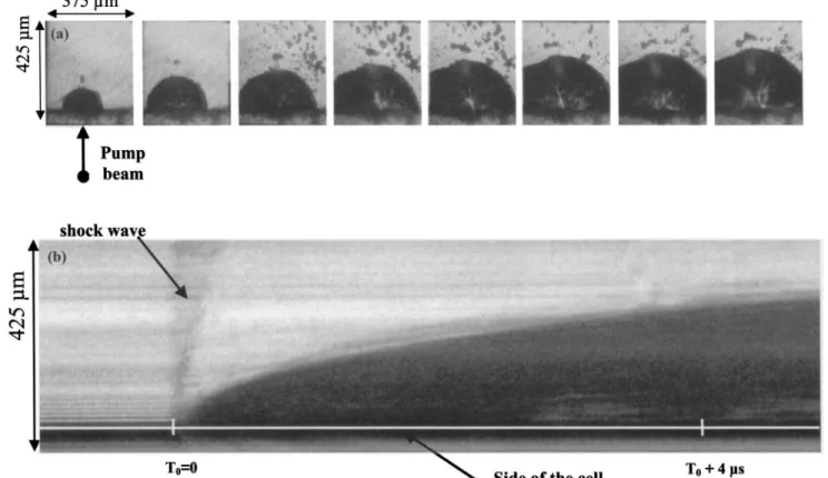
By increasing the input fluence to 50 J/cm2 we were
able to observe plasma formation at the entrance of the cell. Figure 4(a) shows the image sequences at 50 J/cm2. Two features are worth noting. First, one can observe bursts of matter that escape from the vapor bubble cre-ated by the laser beam. Second, there are bright fila-ments inside the gaseous cavity, which seem to emanate from the side and attest to the presence of a plasma. Streak acquisition permits a better quantification of the expansion kinetics of the gaseous cavity [Fig. 4(b)] at 26 J/cm2. At T0 we observe a shock wave following the
ini-tial breakdown in the media. The velocity measured cor-responds exactly to the sound velocity of 990 m/s in chlo-roform. We can also measure the velocity of the cavity expansion. Initially this velocity is approximately 150 m/s; it decreases rapidly to 40 m/s after 5 ms. From these experiments it is not possible to know whether the plasma formation is a phenomenon that follows carbon nanotube sublimation or whether it emanates from the wall of the cell, as the laser beam is tightly focused from the beginning of the cell. Whatever its origin, the plasma formation induces damage in the optical limiter device and is responsible for the optical damage thresh-old.
To compare the bubble evolutions of the chloroform and the water suspensions we performed these measurements in the same experimental conditions for both solvents. Figure 5 shows two sequences obtained with carbon nano-tubes suspended in chloroform and in water for an input fluence of 9 J/cm2at 532 nm. The behavior of water sus-pensions clearly differs from that of chloroform suspen-sions, with better coalescence for water suspensions. Starting from the first image, ;150 ns after the pump pulse the vapor bubbles are less numerous and are ap-proximately twice as large (radii of 10 mm for water and 5 mm for chloroform). For water suspensions, we observe after image 1, two big vapor bubbles that oscillate in phase. These results are in agreement with the theoret-ical scattering model developed by coupling of the Beer– Lambert law and Mie theory with polychromatic pump– probe experiments.13 Indeed, from this analysis we determined the evolution of the concentration and aver-age radius of the scattering centers as well as their vol-ume fraction and observed a slower coalescence in chloro-form suspensions than in water. Moreover, we have demonstrated that scattering in chloroform is due to a large number of small vapor bubbles, whereas in water it is due to a small number of large vapor bubbles.
B. Energy Dependence
In Subsection 4.A we studied the evolution of scattering centers to determine the kinetics of the growth of vapor bubbles in carbon nanotube suspensions in water and in chloroform. Here we are interested in the effects of the input fluence on the number, size, and distribution of gas-eous cavities in the samples. Figure 6 presents, for both suspensions, the images that were saved ;150 ns after the pump pulse for different input fluences. First, we can observe the large number of vapor bubbles in chloro-form suspensions. Second, the size of an individual
cav-ity seems to be independent of the pump fluence, which means that a coalescence phenomenon already occurred earlier than 150 ns after the maximum of the input pump pulse.
At low input fluences of 2 and 4.5 J/cm2in carbon
nano-tube suspensions in chloroform and in water, respectively, the vapor bubble distribution fits the focal volume of the laser beam. However, at high input fluences this distri-bution largely overflows the focal volume. The beam waist is 20 mm, whereas the cloud radius of vapor bubbles varies from ;18 mm at 350 mJ/cm2to ;90 mm at 15 J/cm2
in chloroform. For water suspensions the cloud radius of gaseous cavities varies from 12 mm at 1.5 J/cm2to 70 mm at 22 J/cm2. This variation can be understood as follows:
For low input fluences the interaction with the laser beam occurs over the entire focal zone, as is clearly observable from images numbered 7 and 8 in Fig. 5 for both solvents, whereas at high input fluence there is a large number of bubbles generated out of the focal volume. The presence of bubbles outside the laser interaction zone may have ei-ther of two causes: The bubbles can be new ones created by the laser light scattered outside the focal volume, or
Fig. 1. Shadowgraphic experimental setup coupled with a classic pump–probe experiment with a continuous-wave He–Ne laser: Pc’s, polarizer cubes; PT, fast photocathode; PM, photomultiplier; Pv, Ph, vertical and horizontal polarization, respectively; f1, 200-mm focal-length achromatic doublet; s, sample; D1, D2, input and output photodetectors, respectively; Afocal, a focal lens.
Fig. 2. Illustration of the evolution of solvent vapor bubble growth for carbon nanotube suspensions in chloroform. The images are separated by 500 ns, and image 1 is obtained ;150 ns after the maximum of the input pump pulse. The input fluence at 532 nm is 9 J/cm2.
they can come from motion of the original bubbles caused by thermal activity or electrostriction.
Note that we can observe vapor bubbles starting from 350 mJ/cm2and 1.5 J/cm2for chloroform and water sus-pensions, respectively. Below these input fluences we could not see gaseous cavities with our experimental mag-nification of 403. A reason for this is that the vapor bubble lifetimes are small near the optical limiting threshold, and it is probable that the sample perturbation finishes before the first acquisition begins for low ener-gies.
C. Compression Wave Effect
For high input energy (;15 J/cm2) we notice a strange perturbation of the probe beam (Fig. 7). We can observe two cavitation oscillations that occur within 25 ms after the pump pulse, as already observed (cf. Fig. 3), but we can also observe two unexpected damped images that oc-cur every 40 ms. We attribute these perturbations to the creation of a compression wave. In this hypothesis the time interval corresponds to the propagation of an acous-tic wave that we can calculate to ;40 mm, considering that the velocity of sound in chloroform is 990 m/s. This result is consistent with the reflection of an acoustic wave created in the focal volume on the bottom of the cell, as, in our experiment, the pump and probe beams are approxi-mately 20 mm above the wall of the cell. These pertur-bations of the probe transmittance last, however, for too long a time to result only from index modulation of the medium owing to the reflection of an acoustic wave. The refractive signature associated with such an effect would give a peak-to-valley or a valley-to-peak shape and would be faster. We therefore think that the reflection of the wave reactivates the cavitation phenomenon in the not-yet-recondensed gaseous cavities.
5. NANOSECOND TIME-SCALE RESULTS
We made similar shadowgraphic experiments with an in-tensified CCD camera that allows one to acquire images of the focal volume from 5 to 150 ns after the pump pulse. Fig. 3. Evolution of the probe transmittance and the
transver-sal radius of the vapor bubble cloud for carbon nanotube suspen-sions in chloroform. Zero time corresponds to the maximum of the input pump pulse at 532 nm. The input fluence was 9 J/cm2 at 532 nm.
Fig. 4. (a) Formation and growth of plasma in carbon nanotube suspensions in chloroform. The input fluence is 50 J/cm2at 532 nm.
The images are separated by 500 ns, and the first image (top left) was obtained ;150 ns after the maximum of the input pump pulse. (b) Kinetics of plasma growth in carbon nanotube suspensions in chloroform in streak mode acquisition. The input fluence is 26 J/cm2at
These experiments were performed at 1064 nm to elimi-nate parasitic problems caused by the high sensitivity of the camera in the visible.
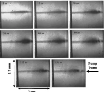
We observed the evolution of the vapor bubbles and the propagation of compression waves created by the pump beam. Figure 8 shows the evolution of bubble growth
Fig. 5. Comparison of the evolution of the scattering centers for carbon nanotube suspensions in chloroform and in water. The input fluence is 9 J/cm2at 532 nm, and the pulse duration 13 ns. The images are separated by 500 ns, and image 1 is obtained ;150 ns after
the maximum of the input pump pulse.
Fig. 6. Dependence on energy of the repartition of the scattering centers for carbon nanotube suspensions in chloroform (from 350 mJ/cm2to 15 J/cm2) and in water (from 1.5 to 22 J/cm2). The images are separated by 500 ns, and image 1 is obtained ;150 ns after the
from 5 to 150 ns from the maximum of pump pulse. We measured one image by laser shot. In the first image the bubbles are confined to the focal volume. Then, as time goes on, we can clearly observe the escape of these bubbles out of the interaction zone, as we have already in-ferred from Fig. 6.
After image 5 we observe two dark horizontal faint streaks, which are due to acoustic-wave propagation in the medium. These acoustic waves are created by the in-tense pump pulse. They can be responsible for a part of the nonlinear refraction observed with 7-ns pulse dura-tion at 532 and 1064 nm.20 It is the rebound of these
acoustic waves that gives birth to the reappearance of the probe perturbation shown in Fig. 7.
6. CONCLUSION
In this paper we have described shadowgraphic experi-ments that have allowed us to illustrate the focal volume during and after the pump pulse in various suspensions of carbon nanotubes. We have also coupled classic pump–
probe experiments with a continuous He–Ne laser as a probe to associate the scattering centers with the probe perturbation.
We have observed, in carbon nanotube suspensions in chloroform on a microsecond time scale, the formation of microbubbles that oscillate in phase as the result of a cavitation phenomenon. In water suspensions an impor-tant coalescence effect leads to the formation of a few macroscopic vapor bubbles, whereas in chloroform sus-pensions we observe numerous microscopic gaseous cavi-ties. This difference can be explained by the larger sur-face tension at the liquid–gas intersur-face for water than for chloroform. This coalescence phenomenon is in agree-ment with a previous experiagree-ment in which the wave-length dependence of the scattered light was measured.13 We have also observed evidence of plasma generation in carbon nanotube suspensions in chloroform under high input fluences (10–20 J/cm2).
At low input fluences the scattering centers are distrib-uted in the focal volume of the pump beam, whereas at high input fluences the vapor bubbles overflow the beam caustic as a result of secondary excitation of nanotubes or of thermal or electrostrictive motion of the bubbles. This phenomenon occurs rapidly after the pump pulse (;20 ns). We have also observed shock waves in carbon nano-tube suspensions in chloroform, generating a surprising effect after beam propagation as an acoustic wave ini-tiates a new cavitation phenomenon after reflection on the walls of the cell.
ACKNOWLEDGMENTS
The authors greatly appreciate the high-quality samples provided by S. Tahir and P. Bernier. We thank M. An-drieux and F. Lafonta for their help and for fruitful dis-cussions. E. Anglaret acknowledges financial support from the De´le´gation Ge´ne´rale pour l’Armement, France.
REFERENCES
1. K. Nashimoto, R. Pachter, B. W. Wessels, J. Shmulovich, A. K.-Y. Jen, K. Lewis, R. Sutherland, and J. W. Perry, eds., Thin Films for Optical Waveguide Devices and Materials for Optical Limiting, Vol. 597 of MRS Proceedings Series (Ma-terials Research Society, Warrendale, Pa., 1999).
2. R. C. Hollins, ‘‘Materials for optical limiters,’’ Curr. Opin. Solid State Mater. Sci. 4, 189–196 (1999).
3. J. W. Perry, ‘‘Organics and metal-containing reverse satu-rable absorbers for optical limiters,’’ in Nonlinear Optics of Organic Molecules and Polymers, H. S. Nalwa and S. Miyata, eds. (CRC Press, Orlando, Fla., 1997), pp. 813–840. 4. R. W. Boyd, Nonlinear Optics (Academic, New York, 1992). 5. B. L. Justus, A. L. Huston, and A. J. Campillo, ‘‘Broadband thermal optical limiter,’’ Appl. Phys. Lett. 63, 1483–1486 (1993).
6. K. J. McEwan, P. K. Milsom, and D. B. James, ‘‘Nonlinear optical effects in carbon suspensions,’’ in Nonlinear Optical Liquids for Power Limiting and Imaging, C. M. Lawson, ed., Proc. SPIE 3472, 42–52 (1998).
7. K. M. Nashold and D. P. Walter, ‘‘Investigations of optical limiting mechanisms in carbon particle suspensions and fullerene solutions,’’ J. Opt. Soc. Am. B 12, 1228–1237 (1995).
8. K. Mansour, M. J. Soileau, and E. W. Van Stryland, ‘‘Non-linear optical properties of carbon-black suspensions (ink),’’ J. Opt. Soc. Am. B 9, 1100–1109 (1992).
Fig. 7. Probe beam perturbation of carbon nanotube suspen-sions in chloroform on a microsecond time scale. The input flu-ence is 15 J/cm2at 532 nm.
Fig. 8. Evolution of scattering centers during the pump pulse from 5 to 150 ns for carbon nanotube suspensions in chloroform. The input fluence is 9 J/cm2at 1064 nm.
9. V. Joudrier, P. Bourdon, F. Hache, and C. Flytzanis, ‘‘Char-acterization of nonlinear scattering in colloidal suspensions of silica particles,’’ Appl. Phys. B 70, 105–109 (2000). 10. L. Vivien, D. Riehl, E. Anglaret, and F. Hache, ‘‘Pump–
probe experiments at 1064 nm in singlewall carbon nano-tube suspensions,’’ IEEE J. Quantum Electron. 36, 680–686 (2000).
11. L. Vivien, D. Riehl, F. Hache, and E. Anglaret, ‘‘Nonlinear scattering origin in carbon nanotube suspensions,’’ J. Opt. Nonlin. Phys. Mater. 9, 297–308 (2000).
12. L. Vivien, D. Riehl, P. Lanc¸on, F. Hache, and E. Anglaret, ‘‘Pulse duration and wavelength effects on the optical lim-iting behavior of carbon nanotube suspensions,’’ Opt. Lett.
26, 26–29 (2001).
13. L. Vivien, J. F. Delouis, J. A. Delaire, D. Riehl, E. Anglaret, and F. Hache, ‘‘Picosecond and nanosecond polychromatic pump–probe studies of bubble growth in carbon nanotube suspensions,’’ J. Opt. Soc. Am. B 19, 208–214 (2002). 14. R. C. Hollins, ‘‘Optical limiters: spatial, temporal and
spectral effects,’’ Nonlinear Opt. 21, 49–60 (1999). 15. P. T. Giovanneschi, P. A. Alloncle, D. Dufresne, Ph. Bournot,
and M. Autric, ‘‘Study of the cavitation induced by a high
power laser beam,’’ in Seventh International Symposium on Gas Flow and Lasers, D. Schuoecker, ed., Proc. SPIE 1031, 545–550 (1989).
16. E. Goedert, R. Becker, A. Clements, and T. Whittaker III, ‘‘Time-resolved shadowgraphic imaging of the response of dilute suspensions to laser pulses,’’ J. Opt. Soc. Am. B 15, 1442–1462 (1998).
17. C. Journet, W. K. Maser, P. Bernier, A. Loiseau, M. Lamy de la Chapelle, S. Lefrant, P. Deniard, R. Lee, and J. E. Fis-cher, ‘‘Large-scale production of single-walled carbon nano-tubes by the electric-arc technique,’’ Nature 388, 756–758 (1997).
18. L. Vaccarini, C. Goze, R. Aznar, V. Micholet, C. Journet, and P. Bernier, ‘‘Purification procedure of carbon nanotubes,’’ Synth. Met. 103, 2492–2493 (1999).
19. S. Rols, R. Almairac, L. Henrard, E. Anglaret, and J. L. Sauvajol, ‘‘Diffraction by finite-size crystalline bundles of single wall nanotubes,’’ Eur. Phys. J.B 10, 263–270 (1999). 20. L. Vivien, E. Anglaret, D. Riehl, F. Hache, F. Bacou, M. An-drieux, F. Lafonta, C. Journet, C. Goze, M. Brunet, and P. Bernier, ‘‘Optical limiting properties of singlewall carbon nanotubes,’’ Opt. Commun. 174, 271–275 (2000).