HAL Id: hal-00258571
https://hal.archives-ouvertes.fr/hal-00258571
Submitted on 18 Apr 2021
HAL is a multi-disciplinary open access
archive for the deposit and dissemination of
sci-entific research documents, whether they are
pub-lished or not. The documents may come from
teaching and research institutions in France or
abroad, or from public or private research centers.
L’archive ouverte pluridisciplinaire HAL, est
destinée au dépôt et à la diffusion de documents
scientifiques de niveau recherche, publiés ou non,
émanant des établissements d’enseignement et de
recherche français ou étrangers, des laboratoires
publics ou privés.
Subwavelength metallic coaxial waveguides in the optical
range: Role of the plasmonic modes
F.I Baida, A. Belkhir, D. van Labeke, O. Lamrous
To cite this version:
F.I Baida, A. Belkhir, D. van Labeke, O. Lamrous. Subwavelength metallic coaxial waveguides in
the optical range: Role of the plasmonic modes. Physical Review B: Condensed Matter and
Ma-terials Physics (1998-2015), American Physical Society, 2006, 74 (20), pp.205419.
�10.1103/Phys-RevB.74.205419�. �hal-00258571�
cal parameters of the structure, a very large effective index and very low group velocities could be obtained. We also establish that, in spite of the metal losses, a reasonable large propagation length could be obtained 共50 m兲 which should allow applications for guiding light in nano-optics.
DOI:10.1103/PhysRevB.74.205419 PACS number共s兲: 78.67.⫺n, 78.20.Bh, 42.79.Gn
Miniaturization of optical components is now a real chal-lenge and takes a large place in the domain of nanotechnol-ogy. New optical devices are currently designed at the mi-crometer scale. Tunable photonic crystals are a significant example of such devices.1 Surface plasmons, which are
lo-calized electromagnetic waves, are used to enhance single-molecule fluorescence2 or to build microdetectors for
bio-logical applications.3The superoptical transmission obtained
when light passes through a metallic array of subwavelength holes,4–6is now used as a detector for organic molecules and
could be useful to modulate, to filter or to polarize light at nanometric scales.6,7 Motivated by transmission problems
through optical near-field probes, some theoretical studies were performed on metallic nanometric cylindrical guiding structures.8,9 Waveguides that can transmit both electrical
and optical signals should also be designed at this scale as proposed in Ref.10. In their paper, Bozhevolnyi et al. clearly demonstrate that a simple groove on a metallic layer can play the role of an effective waveguide for surface plasmons with a relatively very large decay length.
The aim of our paper is to propose another solution for optical connections in nano-sized optical components: we theoretically establish that a coaxial waveguide with submi-crometer radii could guide light with a much larger wave-length and with losses low enough to enable useful propaga-tion distances.
In order to use light 共0.4⬍ ⬍ 1.5m兲 for optical con-nections in nano-optical components, it is necessary to find a structure with small transverse widths and with losses low enough to enable a useful propagation distance. Dielectric materials generally have negligible losses but the transverse confinement is very difficult to obtain with such materials. Some photonic optical fibers have subwavelength channels but the field is delocalized among all the cross sections of the fiber. A dielectric fiber can be easily tapered at a nanometric scale and it can guide light without any cutoff restriction. But
the evanescent part of the guided mode is spread out over the taper, which is not compatible with efficient confinement.
With metallic guides, at first glance, it seems easier to confine the field in a transverse plane, but it is then necessary to seriously discuss the problems of wavelength cutoff and of losses especially if real metals are used. The properties of metallic waveguides can be found in many textbooks 共Ref.
11, for instance兲, but the studies are generally restricted to radio waves or microwaves. For theses spectral domains, the metals are very close to perfect electric conductors 共PECs兲 and losses are treated as a small perturbation. In the optical range, the properties of the metals must be described by a complex dielectric constant with dispersion and losses. For noble metals 共silver, gold, aluminum兲, experimental tables are published12 and a good approximation is given by the
Drude model 共兲 = 1 −p2/共2+ i兲, where
p= 1.374
⫻ 1016rad/ s is the plasma frequency and = 3.21
⫻ 1013
rad/ s a coefficient directly related to the losses. It is important to notice that for those metals, the losses remain small and the imaginary part of the dielectric constant is much smaller than its real part.
For a guiding structure along the z axis, the electric field of a mode can be written in the general form
Eជ= Eជ0共x,y兲ei共␥z−t兲= Eជ0共x,y兲ei共nef f/cz−t兲. 共1兲
The propagation coefficient ␥ is directly related to the effective index of the mode: ␥= nef f/ c. In general, ␥ and
nef f are functions of and they depend upon the geometry
and on the mode. Without losses,␥ is real or purely imagi-nary. For a propagative mode,␥is real; for a nonpropagative evanescent mode it becomes purely imaginary. The cutoff frequency corresponds to the limit between the two kinds of modes. At this limit,␥ and the effective index vanish. For real metals with losses, ␥ is complex and a general discus-sion is very difficult. However, when losses are small, a clear
difference between propagative and attenuated modes re-mains valid: for propagative modes Im共␥兲 Ⰶ Re共␥兲 and a cut-off frequency still exists when Re共␥兲 ⬇ 0.
To propagate light in a guide with a small cross section, it is necessary to find the geometry that has the mode with the largest cutoff wavelength. Figure 1 gives the cutoffs of the fundamental modes of three kinds of waveguide made with PECs. In the following, the cavity inside each guide is sup-posed to be filled with air. In theoretical calculations it is easy to replace air by another dielectric; it is not so easy experimentally. So, in the following all the calculations are performed with air inside the cavities.
For a square or rectangular waveguide 共widths a and b with a 艌 b兲 in a PEC, the fundamental mode with the largest cutoff wavelength is the TE10: c= 2a. By replacing a
rect-angular cross section by a circular one, with the same width 共diameter a = 2R兲, a smaller cutoff is obtained for the funda-mental mode: c= 1.7a for the TE11 mode.
If we consider a coaxial waveguide, in a PEC, a very interesting result is obtained. The cutoff wavelength of all the modes except two depends on the difference between the outer and inner radii, i.e., the wavelength cutoff is very small. But the TEM0 mode has no cutoff 共c= ⬁兲 and the
TEm1mode has a cutoff proportional to the sum of the radii:
TE
m1
c ⯝
共Ro+ Ri兲 / m, where Roand Riare the outer and
in-ner radii, respectively. The TEM0 mode has a cylindrical
symmetry and it should be very difficult to be optically pro-duced. On the contrary the electric field of TE11 is linearly
polarized and could be easily excited.
Thus, except for the TEM0 mode, the fundamental mode
of a coaxial guide in a PEC is the TE11 mode, which has a
rather large cutoff wavelength: TE11 c
⯝共Ro+ Ri兲. If the
ex-ternal transverse width of the coaxial waveguide remains constant, the cutoff wavelength of the TE11 mode can be
increased when the inner radius tends to the external one. The maximum that can be reached is TE
11
c
→共2Ro兲 which
is obtained for a very small gap between the two radii. For optical applications, it is necessary to check if the
interesting properties of the coaxial waveguide remain valid in the optical domain. Here analytical solutions are not pos-sible and it is necessary to use numerical methods. Commer-cial codes are available for this purpose; they are founded upon the finite-difference time domain 共FDTD兲 method or the finite-element method共FEM兲. They have no problems for dielectric structures but they have shown erratic problems of convergence when applied to our nanoguiding structures with real metals.
The cutoff frequencies and the light distribution inside the waveguide, which will be shown below, are calculated via an original FDTD code that will be briefly described here. The study of axially symmetrical structures can be easily done by the body-of-revolution FDTD 共BOR FDTD兲 method which is based on the discretization of the Maxwell equations ex-pressed in cylindrical coordinates.13,14 The N-order FDTD
method15,16 is then adapted to such a symmetry. To our
knowledge, this method is not yet recognized in cylindrical
FIG. 2. Effective index of the first guided modes for coaxial and cylindrical waveguides made in PEC and in silver. The radius of the cylindrical waveguide is set to R = 125 nm, the outer radius of the coaxial waveguide is Ro= 125 nm, and the inner one is Ri= 75 nm.
FIG. 3. Variations of the cutoff wavelength of the first mode of the two structures共coaxial and cylindrical兲 versus outer radius. For the coaxial waveguide, the inner radius is set to Ri= 75 nm. FIG. 1. 共Color online兲 Cutoff wavelengths of the first guided
modes共associated with bigger values of wavelength兲 for three dif-ferent waveguides made in a PEC.
BAIDA et al. PHYSICAL REVIEW B 74, 205419共2006兲
coordinates; however, it leads to an efficient and fast code as it avoids the use of absorbing boundary conditions except in the radial direction. Moreover, we have also used for these calculations, a nonuniform mesh: the smallest spatial step was␦r= 0.1 nm near the edges whereas␦r= 5 nm elsewhere.
Let us notice here that studies on optical fibers by the FDTD method are generally performed with a two-dimensional 2D algorithm with rectangular discretization17,18
which is not very well adapted to efficiently describe the cylindrical geometry of the studied structure.
In our case, the dispersion of metals at optical frequencies is easily incorporated in the FDTD algorithm via the discreti-zation of the constitutive equation of the medium that con-nects the displacement Dជ vector to the electric field Eជ.19
In order to test the validity of our approach, we first de-termine the dispersion curve for a coaxial waveguide in a PEC and compare the result with the same structure in silver. An example of the dispersion curves is presented in Fig.2
where are plotted the variations of the effective indices of the first modes 共TEM0, TE10, and TE11兲 versus the vacuum
wavelength for two different geometries.
The dispersion curves of the PEC structure, obtained with our FDTD code, exactly correspond to the theoretical ones. The TEM0 mode has no cutoff and its effective index is
equal to 1 along the whole spectrum. The effective index of the TE1 mode verifies the simple equation nef f
PEC
共兲 =
冑
1 − 2/共c兲2.For the coaxial waveguide in silver, only two modes have a propagative part in the studied spectral range. A mode with
cylindrical symmetry is found, its cutoff wavelength far be-yond the infrared, and the effective index exhibits a small dispersion from 0= 600– 900 nm共even up to 1600 nm兲. It is
important to notice that the effective index of this mode is larger than 1. The other mode has a field distribution corre-sponding to an m = 1 mode. The two modes have, in the case of silver, small Ez field components so they are not pure
TEM0 and TE1 modes, but they are in the continuity of the
previously described modes of the PEC structure and they will be named in the following the TEM0
⬘
and TE11⬘
modes.The TE11
⬘
mode has a dispersion curve which looks likethe PEC one but is pushed towards the red region of the spectrum. For a real noble metal, the cutoff wavelength is increased compared to the same structure in the PEC. A simi-lar result has also been recently established for the mode propagation in rectangular20 or cylindrical18structures made
of real metals. So a general property can be expressed: for a guiding structure made in real metal, the cutoff wavelength of a propagative mode is increased when compared with the same mode of the same structure made in a PEC. This result is a key point for the interpretation of the very large trans-mission obtained with an annular aperture array.16 The
red-shift depends both on the value of the plasma frequency共wp兲
used in the Drude model and on the geometrical parameters of the waveguide共radii兲. Moreover, the loss coefficientof the permittivity has a very small influence on the cutoff shift. It is important to notice that, among the three studied structures with the same external radius, the coaxial wave-guide in silver is the structure which has propagative modes with the largest wavelength.
shown. The dashed line presented on the four figures corresponds to = p/
冑
2.Another interesting phenomenon is presented in Fig.3. In this figure we have plotted the variations of the cutoff wave-lengths versus the outer radius Roof the fundamental modes
for four structures: a coaxial waveguide in PEC or silver and a cylindrical waveguide also in PEC or silver. For the two coaxial waveguides, the inner radius is fixed to Ri= 75 nm.
For a cylindrical waveguide made in PEC or silver, the behavior of the cutoff is linear but it is shifted toward the red region of the spectrum in the case of real metal. We have also
reproduced the result presented in the inset of Fig. 2共a兲 by Shin et al.18
The cutoff wavelength of the TE11 mode of the coaxial
waveguide made in the PEC varies linearly with respect to the outer radius and verifies the theoretical equation TE11
c
⬇共Ro+ Ri兲. All these results are tests showing the good
accuracy of our FDTD code.
But for a coaxial waveguide made in silver 共metal with losses兲 one can see in Fig. 3 that the variation of the cutoff wavelength of the TE11
⬘
mode exhibits an unusual behavior when the external radius decreases. For a large external ra-dius, the cutoff wavelength first decreases linearly, but, be-low a limiting value 共point F on the figure兲 Romin
= 125 nm, the cutoff wavelength increases when Ro decreases. This
finding is at the origin of the enhanced transmission obtained through annular aperture arrays with a small gap between Ro
and Ri when illuminated by very large incident
wavelengths.21
In order to explain this unusual behavior of the cutoff wavelength in the case of a coaxial waveguide in real metal, we study the evolution of the dispersion curves when Ro
varies and for a fixed value of Ri= 75 nm. The calculations
are performed only for modes having the same azimuthal number m = 1.
Figure4shows the results obtained for only four values of
Roaround the point F of Fig.3. The higher modes are
propa-gative ones and, as usual, they tend asymptotically to the light line for large values of kz. For small values of Ro, these
modes are shifted toward high frequencies; they do not ap-pear in Fig.4共d兲 for Ro= 80 nm.
The two interesting modes are the lowest ones. Actually, they cut the light line and tend asymptotically to=p/
冑
2which is the surface plasmon frequency on a flat metal-vacuum interface. When Rodecreases, the two curves repels
each other and a large gap is obtained for Ro= 80 nm. These
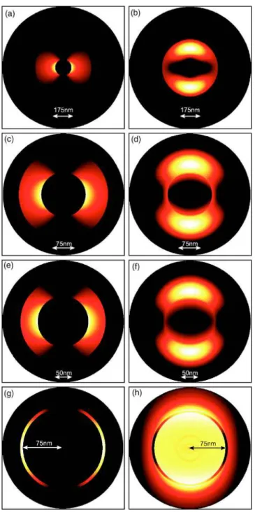
FIG. 5. 共Color online兲 Light distributions 共square modulus of the electric field兲 in a section of the waveguide for four values of Ro
and with Ri= 75 nm. In all the eight subfigures, kzis set to zero, i.e.,
is equal to c.共a兲, 共c兲, 共e兲, and 共g兲 correspond to the lower mode
while共b兲, 共d兲, 共f兲, and 共h兲 are calculated for the second plasmonic mode.
FIG. 6. Normalized group velocity 共by c兲 of the lower mode versus the wavelength for Ro= 125 nm and Ri= 75 nm.
BAIDA et al. PHYSICAL REVIEW B 74, 205419共2006兲
the case of a 1D metallic photonic crystal.22 In the former
case, one of them has an odd symmetry while the other pre-sents an even one. In our case, there is no geometrical sym-metry in the radial direction except when Ro→ Ri; this
im-plies that there are no even or odd symmetries. Figure 5
shows the light distribution at cutoff wavelengths for the two lower modes in the case of a coaxial waveguide made in silver with Ri= 75 nm and for the four values of Ro
consid-ered in Fig.4. One can see that for the fundamental mode, the light distribution corresponds to the excitation of a sur-face plasmon on the inner intersur-face whichever the value of the outer radius. Moreover, for the second mode, the maxima of light are located between the two interfaces. We have verified that these two modes are TE1n-like ones, i.e., at the
cutoff, Er, E, and Hz are not equal to zero while the three
other components 共Ez, Hr, H兲 of the electromagnetic field
are null.
Note here that for an outer radius of Ro= 80 nm 关Fig. 5共h兲兴, the cutoff wavelength of the second mode is almost equal to c= 140 nm which corresponds to =p. In this
case, the dielectric constant of silver becomes null and a plasmon resonance共in the volume兲 is obtained as shown in Fig.5共h兲.
It seems that, when Ro→ Ri, the cutoff frequency tends to
zero for the fundamental mode and to p for the second
plasmonic mode. It would be interesting to have a theoretical interpretation of this phenomenon.
Figure4共d兲shows also that, for a small value of the outer radius 共here Ro= 80 nm兲, the dispersion curves become
al-most horizontal. The group velocity vg is then small
com-pared to c 共light velocity in vacuum兲. Figure 6 shows the group velocity versus the wavelength of the lowest guided mode in the case of a silver coaxial waveguide with Ro
= 125 nm and Ri= 75 nm. This curve is simply numerically
calculated from Fig.4共c兲by vg= d/ dk. We have performed
many other calculations which demonstrate that for Ro→ Ri
→ 0, the dispersion curve becomes more flat and, conse-quently, the group velocity decreases共for example with Ro
= 55 nm and Ri= 50 nm, we get vg⬍ c / 4 for the whole
vis-ible region兲. In all cases, the value of vg falls to zero at the
cutoff because there is no propagation along the z axis 共kz= 0兲.
These modes are interesting because of their large cutoff wavelengths 共especially the lowest one兲. Nevertheless, for
practical applications, it is necessary to determine the propa-gation losses. It is clear from Fig.5that, for the fundamental mode共TE11
⬘
兲, light is essentially confined in the gap betweenthe two metallic parts of the waveguide. This indicates that losses should be very weak during the propagation.
In order to confirm that, let us determine the imaginary part of the effective index共nef f= nef f
⬘
+ inef f⬙
兲. The real part nef f⬘
共which is presented in Fig.2兲 is determined from the disper-sion curves given in Fig.4by nef f
⬘
= ckz/ 2. The imaginarypart of nef f can be determined by studying the width of the
resonance peaks obtained by the N-order FDTD method.23 But this method is not sufficiently accurate in our case. Thus, we have determined it by performing a numerical propaga-tion experiment. A body-of-revolupropaga-tion FDTD calculapropaga-tion on
with Ri= 75 nm. Distances AB and BC were set to zB− zA= zC− zB
= 500 nm and the injection point I was located at 500 nm above A 共see Fig.7兲.
FIG. 9. Comparison of the efficiency of the diffracted zero order by four different single coaxial apertures pierced into a metallic layer. For all, the metal thickness is set to h = 100 nm and the struc-ture is supposed to be free standing共surrounded by vacuum兲. Dot-ted line corresponds to a PEC structure with Ro= 90 nm while the solid line corresponds to the same structure in silver. The dot-dashed line and the dot-dashed one are both calculated for Ro = 125 nm and for PEC and silver metal, respectively.
a z-finite structure is performed and the imaginary part of the effective index is determined by measuring the light attenu-ation. The schema of the studied structure is presented in Fig.7.
A pulsed guided mode is injected at the point I. This pulse is centered around = 500 nm and has a small temporal width in order to cover the whole visible range. Three point detectors are set at A, B, and C. The three components关Er共t兲,
E共t兲, and Ez共t兲兴 of the electromagnetic field are then
re-corded versus time at these three points.
A time Fourier transform is then made over each compo-nent in order to determine the spectral densities IA, IB, and IC.
Thus, the imaginary part of the effective index can be easily calculated from one of the following equations:
n
⬙
= ln共IA,B or C/IB,C or A兲 4共zB,C or A − zA,B or C兲. 共2兲 One notice here that this BOR FDTD calculation is time consuming共36 h on a laptop computer Dell Precision M70兲 because of the small spatial meshing in the radial direction 共␦r= 0.1 nm兲 which leads to a very small time step in the
FDTD code 共␦t⯝ 1.35⫻ 10−19s兲 and also because of the
weak value of the group velocity.
On the other hand, this method remains valid only for wavelengths less than the cutoff. In fact, for = c, the group
velocity of the guided mode is zero and the light does not propagate.
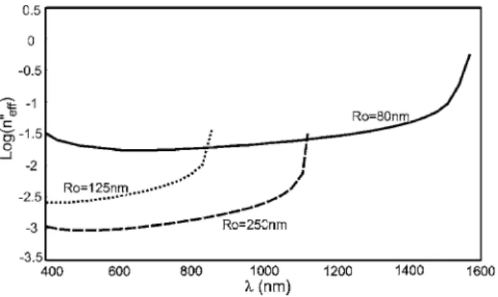
Because of this, Fig. 8 presents the logarithm of the imaginary part of the effective index only for ⬍ cfor three different geometrical configurations. For all three cases Riis
fixed to 75 nm. The dotted line is obtained for Ro= 125 nm,
the dashed one for Ro= 250 nm, and the solid one in the case
of Ro= 80 nm.
Figure 8 shows that the imaginary part of the lower guided mode 共the TE11
⬘
one兲 increases when Ro decreases,and then the decay length decreases. Moreover, nef f
⬙
is around2 ⫻ 10−3for the whole visible range when R
o= 125 nm. This
corresponds to a decay length of 50m共in average兲. Thus, this mode presents weak losses during its propagation and waveguides of several tens of micrometers can be designed for optical applications.
On the other hand, this finding can be used in the domain of enhanced transmission through subwavelength apertures as studied by Haftel et al.21 In that study, the authors
dem-onstrate that by decreasing the value of the outer radius, the transmission peak is shifted toward large wavelength values. Figure9 shows the zero-order efficiency of a 100-nm-thick silver layer perforated by only one aperture. Four apertures were studied: cylindrical and coaxial ones in PEC and in silver, and two different geometrical configurations.
Two phenomena are clearly shown on Fig.9: first, the use of silver instead of PEC leads to a shift in the transmission peak toward a larger value of wavelength and, second, this shift can be amplified by decreasing the outer radius.
To the best of our knowledge, this work shows for the first time the determination of cutoff frequencies of a real metal-lic coaxial waveguide. In addition, the abnormal behavior of the cutoff wavelength of the fundamental mode is pointed out: it increases when the outer radius decreases. The group velocity of such a mode shows a weak value compared to c, which means that light will propagate slowly inside the waveguide. This property is very important if we consider nonlinear or electro-optical materials placed between the in-ner and the outer metallic parts because their coefficients can then be strongly increased with slow light.
This work is partly supported by the European Network of Excellence on Micro Optics NEMO共WP13兲. The grant of A.B. is funded by international collaboration between France and Algeria.
*FAX: 00 共33兲 3 81 66 64 23. Electronic address: fbaida@univ-fcomte.fr
1M. Roussey, M.-P. Bernal, N. Courjal, and F. I. Baida, Appl.
Phys. Lett. 87, 241101共2005兲.
2H. Rigneault, J. Capoulade, J. Dinitnger, J. Wenger, N. Bonod, E.
Popov, T. W. Ebbesen, and P. F. Lenne, Phys. Rev. Lett. 95, 117401共2005兲.
3J. Wenger, H. Rigneault, J. Dintinger, D. Marguet, and P.-F.
Lenne, J. Biol. Phys. 32, SN1共2006兲.
4T. W. Ebbesen, H. J. Lezec, H. F. Ghaemi, T. Thio, and P. A.
Wolff, Nature共London兲 391, 667 共1998兲.
5F. I. Baida and D. Van Labeke, Opt. Commun. 209, 17共2002兲. 6F. I. Baida and D. Van Labeke, Phys. Rev. B 67, 155314共2003兲. 7F. I. Baida, Y. Poujet, B. Guizal, and D. Van Labeke, Opt.
Com-mun. 256, 190共2005兲.
8L. Novotny and C. Hafner, Phys. Rev. E 50, 4094共1994兲. 9Ursula Schröter and Alain Dereux, Phys. Rev. B 64, 125420
共2001兲.
10Sergey I. Bozhevolnyi, Valentyn S. Volkov, Eloîse Devaux, and
Thomas W. Ebbesen, Phys. Rev. Lett. 95, 046802共2005兲.
11J. D. Jackson, Classical Electrodynamics, 2nd ed. 共John Wiley,
New York, 1975兲.
12P. B. Johnson and R. W. Christy, Phys. Rev. B 6, 4370共1972兲. 13D. B. Davidson and R. W. Ziolkowski, J. Opt. Soc. Am. A 11,
1471共1994兲.
14A. Taflove and S. C. Hagness, Computational Electrodynamics:
The Finite-Difference Time-Domain Method, 2nd ed. 共Artech House, Norwood, MA, 2000兲.
15C. T. Chan, Q. L. Yu, and K. M. Ho, Phys. Rev. B 51, 16635
共1995兲.
16F. I. Baida, D. Van Labeke, G. Granet, A. Moreau, and A. Belkir,
Appl. Phys. B: Lasers Opt. 79, 1共2004兲.
17Yong Xu, Reginald K. Lee, and Amnon Yariv, Opt. Lett. 27,
1019共2002兲.
18Hocheol Shin, Peter B. Catrysse, and Shanhui Fan, Phys. Rev. B
72, 085436共2005兲.
BAIDA et al. PHYSICAL REVIEW B 74, 205419共2006兲