© 2021 ISTE OpenScience – Published by ISTE Ltd. London, UK – openscience.fr Page | 1
The efficiency of turbomachinery in the zero- and
three-dimensional approaches
Deux méthodes de détermination de l'efficacité des turbomachines dans
des approches 0D et 3D
Paweł Ziółkowski1
, Tomasz Kowalczyk2, Janusz Badur3, Michel Feidt4
1 Gdańsk University of Technology, Faculty of Mechanical Engineering, Department of Energy and Industrial Apparatus,
Narutowicza 11/12, 80-233 Gdansk, Poland, [email protected]
2, 3
Institute of Fluid Flow Machinery Polish Academy of Sciences, Energy Conversion Department, Fiszera 14, 80-231 Gdansk, Poland, [email protected], [email protected]
4
University of Lorraine, Laboratory of Energetics & Theoretical & Applied Mechanics 2, Avenue de la Forêt de Haye, 54518 Vandœuvre-lès-Nancy, France, [email protected]
ABSTRACT. Efficiency of turbomachinery is usually defined using an isentropic process. This approach provides a reliable reference point only when pressure and temperature measurements are available, e.g. at the casing inlet and outlet. In the case of a single stage internal efficiency determination the reference point is difficult. Computational fluid dynamics allows for an exact calculation of values of losses occurring in a turbine stage from turbine blades geometry, clearances, uneven steam distribution and other. Present method is a three-dimensional polytrophic approach based on work comparison of a turbine stage using real and ideal working fluid. The reference state is estimated by iterative simulation of considered geometry using the Eulerian model of compressible fluid. This approach is more convenient and feels natural when using 3D modeling. Moreover, calculations conducted for a control stage indicated differences between results attained using those two approaches less than 0.2%.
KEYWORDS. efficiency, entropy, CFD, zero-dimensional, three-dimensional, turbine stage, isentropic, polytrophic.
1. Introduction
The cycle efficiency definition, either of heat engines or of turbine stages, has its starting point in the work of Sadi Carnot [BAD 09, CAR 24]. In works [PAM 43, ZEU 98] thermal efficiency is related to transition of a working fluid, which should provide conversion of heat energy into mechanical energy. Carnot discovery is important, since it sets up a concept for constructing heat engines – by introducing an ideal conversion of heat into work in which, in Carnot’s words, there are no “blank
passages of the caloric”. Therefore, the energy conversion in the working fluid into work takes place
with preserved entropy. At that time, the concept of determining the maximum allowable work that can be achieved from the thermal energy of the ideal working medium was also created, while the knowledge about the non-ideal working medium, about its cumulative energy loss, was included in the Carnot coefficient, today called internal efficiency of device (denoted commonly with ). The difference between an ideal medium and a real medium that defines inevitable losses, was mathematically described with the loss coefficient .
Today the concepts of losses and efficiencies are the key in the process of designing of thermal engines. Similarly to the practice of Carnot and other pioneers, the approach in designing is still the same – first an object for an ideal medium is designed, medium possessing viscosity and non-turbulence but perfectly thermal conducting and diffusing. Then the real gas corrections are implemented through more or less correct choices [FEI 17, STO 45, SZE 87]. Owing to repeatedly corrected knowledge, the magnitudes of the losses attributed to all spectra of devices are predicted today with increased accuracy. Difficulties emerge only in the case of new constructions or in cases of solutions for modernization. In other words, Carnot approach may be summarized with the following verbal rule:
© 2021 ISTE OpenScience – Published by ISTE Ltd. London, UK – openscience.fr Page | 2 ( ) ( ) ( ) ( ) [1] Or mathematically [FEI 09, GUN 99, SZE 87]:
̇ [2]
The ideal work of a turbine stage or the entire turbine achieved from a mass unit of the medium is denoted with t, that stands for reversible “theoretical” – in this way an ideal conversion of available energy of steam is denoted [NAS 12, SZE 87]. Equation [2] represents the character of the traditional approach to design – first the thermodynamic cycle is being designed for one kilogram of an ideal working fluid, next the resulting specific work is decreased due to the internal efficiency of transition of real working fluid and it is then multiplied by the resultant amount of working fluid kilograms. Internal efficiency is an empirical parameter, known a priori for similar devices. However, the magnitude of cross sections to possess the required capacity ̇ is derived based on an ideal flow-capacity ̇ as ̇ ̇, where is used to restrict the value of the theoretical flow capacity accordingly to the real velocity profile. Therefore is kind of a flow efficiency connected strictly with friction in a real fluid, which induce higher pressure drop.
In accordance with the current computational tools’ possibilities based on the three-dimensional modeling, the natural question arises as to the agreement between the Computational Fluid Dynamics (CFD) and classical line of reasoning in traditional design. The question is whether concepts such as internal efficiency or losses may be strictly defined in the three-dimensional approach, in other words – are these concepts general, independent on the tool being used. In the following sections we propose consistent definitions for internal efficiency, to allow for transforming computed integral quantities received from three-dimensional (3D) models into zero-dimensional (0D) codes.
The article is original and deals with solving a current problem that has arisen now in the design of stages of steam and gas turbines. Numerical calculations of the CFD type in 3D approach expand the current techniques of constructing turbines, where only 0D analyzes were used. However, the correct definition of internal efficiency in both of these approaches is not unequivocal and therefore the original task is to properly define it. Additionally, the paper presents an example of how the internal efficiency is shaped using the CFD approach for different values of axial and radial clearance. Taking into account the above facts, the issue developed in this paper is of fundamental technical importance, as it supports the design process allowing for precise determination of internal efficiency (casing efficiency). On the other hand, from the scientific point of view, the meaning of the article is revealed both at the basic and application level. The basic question arises what internal efficiency is when we have different models of a fluid at our disposal, namely Euler's fluid and a fluid close to the real one, namely: with turbulence, viscosity and heat conduction included. On the application side, the significance of this work is revealed by the fact that the use of CFD tools and their correct interpretation gives an opportunity to improve the casing efficiency and quality of steam and gas turbines.
2. Definition of turbine stage power, work, and internal efficiency
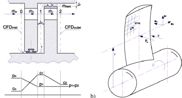
Presented work is based on example of turbine stage, however as it was mentioned before, the proposed approach is valid for other heat engines as well. Fig.1a presents an impulse stage of an axial steam turbine with pressure and velocity distribution along the stage. It comprises stator vanes (subsonic nozzles) and the rotating blades (Fig.1b). It is very easy to define geometrical parameters, such as a pitch diameter, axial clearance and radial clearance . In zero-dimensional modeling it is assumed, that the steam parameters are averaged in sections, are given at pitch diameters, and are denoted – in accordance to the tradition initiated by the pioneers of turbine technology – by 0, 1, 2, respectively. In the zero-dimensioned model information on the geometry on the segment 0-1 and 0-2
© 2021 ISTE OpenScience – Published by ISTE Ltd. London, UK – openscience.fr Page | 3
is not provided. The question on the flow capacity of the stage or the entire turbine is fundamental for the determination of its performance and working parameters. It is important to remember that the turbine is a device converting a working medium internal energy into mechanical work, which is then received at the rotating blades. The internal energy of the working medium first needs to be converted into kinetic energy in the expansion device called the nozzle, and then is forwarded and absorbed at the moving surfaces of the rotor blades.
Thus, unlike reciprocating engines, where working medium is at some temporal instance relatively at rest, in the axial and radial turbines it is constantly flowing through the device [CAR 24, FEI 17, FEI 09, GUN 99]. Mathematically it is the mass flow rate ̇. According to Rankine, an overdot denotes the material time derivative of mass – it is consistent with the material velocity of the volumetric mass density ̇ found in three-dimensional models [BAD 09]. In other words, energy conversion occurs in the medium flow through a fully expansive device (nozzle, vane) and a rotating device (rotor).
a) b)
Figure 1. a) Geometry of an axial impulse stage of a turbine with working medium parameters written for pitch radius, where the mass flow rate of the steam flown is defined as follows: ̇ – in point 0, ̇ –through stator
vane channel, ̇ – through rotating blades channel, ̇ – through leakage. b) Illustration on the
computation of the rotor power with use of momentum conservation equation, where: – radial vector, – blade drift force in zero-dimensional model, – blade drift velocity, – unit normal
vector.
To maintain a constant mass flow rate: ̇ of the working fluid through stage and its clearances, a constant pressure difference between the stage inlet and outlet needs to be exerted: and
. For the entire turbine we usually know both pressures, as these are the pressure of the live steam and the pressure in the condenser or extraction point. Usually it is assumed that these pressures are constant in the measurement cross sections, which allows to identify the pressures at the wall (or inside an insulation) with the zero-dimensional model pressure.
This assumption of equal pressure across the characteristic cross sections is not made in CFD modeling. However, we can assume that the weighted average pressure of the medium in the cross sections at the turbine inlet and at the turbine outlet is equal to the value assumed in the design approach (0D). Additionally, this average cross-sectional pressure in terms of CFD should be equal to the static pressure obtained from the experimental measurements. The three-dimensional CFD model allows for “reading” the value of the pressure precisely at the measurement point. It is possible now to explain the difference between the zero-dimensional and measured pressures – those differences are significant and may reach up to 2 bars [NAS 12].
Mathematically, a mechanical energy flux, expressed by the working medium parameters, is defined by the Umov-Volterra energy flux [BAD 09, BAD 20, BAD 18]: , that is the product of the
© 2021 ISTE OpenScience – Published by ISTE Ltd. London, UK – openscience.fr Page | 4
momentum flux tensor (known as Cauchy stress tensor) and the material velocity vector of the fluid. It is a sufficiently general definition embracing turbulent, diffusive and thermal stresses. Mechanical power received through the Umov-Volterra energy flux on a rotating blade , oriented with a normal vector , is equal to [BAD 09, BAD 20]:
∬ [3]
Here, is a symmetric tensor of the entire momentum flux, comprising, respectively, elastic pressure tensor, traceless viscous stress tensor, Reynolds turbulent stress tensor, diffusion stress tensor, and other, rarely employed with respect to working fluids (e.g. radiation stress tensor in gas turbines). In CFD models of fluids without velocity slip on a wall, fluid velocity used in equation [3] is equal to velocity of the rotation in Fig. 1b).
Even though the is included in the energy equation, in CFD it is computed entirely and solely from the momentum balance equation. Thus, in the case of the fluid tensor model restricted only to elastic Eulerian fluid, i.e. , where pressure is computed from a polytropic process, the circumferential power for the Eulerian fluid, say , may be expected to be far greater than the power acquired for a viscous, turbulent and non-adiabatic fluid. Note, that computation of the circumferential power in the zero-dimensional model (eq. [5]), based on the zero-dimensional momentum balance, has a similar character as in eq. [6] – it is the product of the average force in the circumferential direction and the velocity. Preliminary zero-dimensional modeling, without geometry is based on the balance of enthalpy (eq. [4]). Summarizing the definition of the stage – it is defined differently, depending on the stage of the design process, and determined [BAD 09, KOS 09, PUZ 92, SZE 87, ZEU 98]:
Zero-dimensional design with no geometry [CAR 24]: ̇ [4] Zero-dimensional verification with geometry[FEI 17]: [5] Three-dimensional design/verification[FEI 09]: ∬ [6] where ̇ stands for the mass flow rate of the steam flown through rotor channel. The circumferential force at the rotor equals ̇ . The surface integral in eq. [6], including all blades of the rotor, is computed as an average work of the pressure and the surface tensile forces ∬ on the variable over the blade height velocity (Fig. 1b). The unit vector is the normal vector of the blade surface – it generally changes significantly over the blade’s circumference, but since three-dimensional blades are employed, vector also changes over the blade’s height. The above definitions of the stage power are equivalent. Equivalence of the equations [4] and [5] is shown in many works [GUN 99, KOS 09, PUZ 92]. Transition from eq. [6] to eq. [5] is also often proved qualitatively and quantitatively in numerous works of the authors [NAS 12, PUZ 92].
In practice, comparison of the real powers computed in zero-dimensional and three-dimensional model is a very delicate matter. In the zero-dimensional model there are four free parameters that are determined through empirical closures and verified inside the construction offices of the modern turbine factories [KOS 09, NAS 12]. In the three-dimensional approach, the number of free parameters is several times greater – the designer may improperly pick one of those with an error, in consequence, far greater than in the standard calibrated zero-dimensional model [BAD 09, NAS 12].
The basic quantity for the analysis of the unit power of the turbine stage is the unit circumferential work of the rotor [KOW 17, SAJ 57, STO 45, SZE 87, TRA 77]:
© 2021 ISTE OpenScience – Published by ISTE Ltd. London, UK – openscience.fr Page | 5
̇ [7]
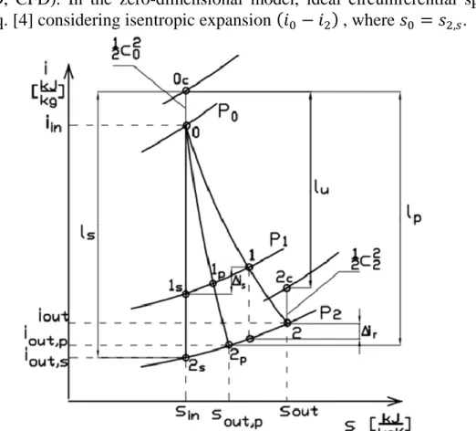
i.e. the work obtained from one kilogram of working fluid hitting the blades of the rotor palisade. Only the mass flow rate flowing through the rotor is considered and the flow through clearances is omitted: ̇ ̇ ̇ . Fig. 2 shows both theoretical processes (isentropic and polytropic) compared to the real process with geometrical description of the energy balances in the turbine stage. In this figure enthalpies: isentropic , and polytropic calculated for a single stage in 0D and 3D analysis can be determined. It can be seen that the enthalpy drop in the 0D view is greater than in the 3D view, but in Fig. 2 the leakage ̇ cannot be taken into account, so at this stage it is not possible to say which casing efficiency is greater.
Ideal specific work on the circumference, , is computed similarly to the real circumferential specific work , but for the theoretical power and theoretical mass flow rate ̇ . Depending on the employed model, the theoretical work becomes isentropic (zero-dimensional – 0D) or polytropic (3D, CFD). In the zero-dimensional model, ideal circumferential specific work is computed from the eq. [4] considering isentropic expansion , where .
Figure 2. Geometrical representation of the energy balances in the turbine stage presented in the i-s graph, where: points of process as follows: 0, 1, 2- real; 1s, 2s - isentropic; 1p, 2p - polytropic; 0c, 2c - with kinetic
energy; - kinetic energy in point 0; specific work of a stage: – circumferential, – isentropic, - polytrophic; Losses : - stator, – rotor, - at outlet connected with the unused kinetic
energy of the fluid;
The definition of the internal efficiency of the stage – let it be denoted with - is extremely important. It includes all non-blade losses, in this case form of shroud leaks. Hence, instead of the equation employed in zero-dimensional modeling: , a more primal definition of internal stage specific work may be used:
̇ [8]
where power is related to the entire mass flow rate flowing through the stage, not only to the mass flow rate passing through the blading ̇ . Since leakages are always greater than zero, .
© 2021 ISTE OpenScience – Published by ISTE Ltd. London, UK – openscience.fr Page | 6
Theoretical internal specific work may be computed identically using theoretical power and mass flow rate ̇ .
The difference between the real power and the ideal power may serve for determination of work losses , which, on the other hand, are empirically determined in the classical zero-dimensional model [SZE 87, TRA 77, ZEU 98].
Internal (casing) efficiency of the stage is defined as the ratio of the internal stage specific work to the ideal stage specific work [KOS 09, ZIÓ 19]:
[9]
In the zero-dimensional model (0D), internal stage losses comprise enthalpy losses of the stage along with the non-blade losses from leaks [SAJ 57, STO 45, SZE 87]:
[10]
where : and denotes stator and rotor blades losses, and are the losses from axial and radial leakages, outlet loss connected with the unused specific kinetic energy of the fluid. Numerous equations available in literature for particular losses may be easily found [KAR 04, KOS 09, KOW 17, ZEU 98].
On the other hands, three-dimensional model losses cannot be separated and attached to particular processes, and are usually given aggregately as [NAS 12]:
̇ ̇ ̇ ̇ [11]
3. Relation between isentropic and polytropic efficiency
To gain a better understanding of the differences between isentropic and polytropic efficiencies, it is profitable to consider this aspect apart from the turbine stage and look at it in a wider perspective, that is in the case of a flow where no heat transfer neither moving surfaces take place. It should be pointed out, that the flow efficiency is connected with the general concept of the ratio of utilization of the energy stored by the unit of mass of a working medium; it describes the relation of real enthalpy change of the medium to some referential (theoretical) change of energy of the medium, which mathematically is: ∫ ∫ ∫ [12] where may be an internal energy, free energy, free enthalpy or any other energy expressing elastic properties of the fluid, and is the time of flow.
Classical isentropic efficiency of a flow, computed in the zero-dimensional modeling, employs isentropic drop [FEI 17, GUN 99, PAM 43], ( :
[13] This definition is practical for the zero-dimensional model, since it is related to the ideal state described by enthalpy – it is easily interpreted in the Mollier i-s chart (Fig. 2) and does not
© 2021 ISTE OpenScience – Published by ISTE Ltd. London, UK – openscience.fr Page | 7
require the temperature to be known. However, the definition for the isentropic efficiency does not have a solid physical fundament, since the process cannot happen in the real fluid flow.
The polytropic definition also does not require the temperature to be known initially; energy dissipation intensity is calculated in the three-dimensional model solely for the real process , or in the case of Eulerian fluid – for available energy drops to zero – the process becomes polytropic [STO 45]. Hence, in the three-dimensional modelling based in CFD approach, the polytropic efficiency definition is:
∬ ∬ ̇ ̇ [14]
However, as proposed by Puzyrewski [PUZ 92] for a zero-dimensional approach, the polytropic efficiency seems more natural than and is defined:
∫ ̇
[15] where ̇ is the rate of pressure change. It follows from the above equation that the difference between isentropic efficiency and polytropic efficiency lies in a different referential state for the energy drop. In the work of Puzyrewski [PUZ 92] evaluation of the difference is found to be:
( ̅ ̅
̅ ) [16]
where: isentropic loss is typically experimentally obtained, the over bar denotes averaged temperature of the thermodynamic process. The zero-dimensional (0D) and three-dimensional (CFD) internal efficiency can be written [NAS 12, PUZ 92] as:
[17] [18] where: Pu is the Puzyrewski number. The equations [17] and [18] show that both efficiencies are close to one another by their values, if [PUZ 92]:
( ̅
̅ ) [19]
For turbine stages it varies from 0.002 to 0.0001, which in design practice means that for the casing efficiency comparison: the polytropic efficiency reaches values of 0.01-0.2% higher than the isentropic efficiency . It is close enough to justify the well-known assumption that .
4. Results of the control stage modelling
The approach presented above is employed for estimation of the control (impulse) stage of a 100MW steam turbine [NAS 12]. The stage is fed with steam through four nozzle boxes, of which one is opened in 80% of its flow capacity. In this case, the guide diaphragm leak is absent ̇ , while there appear losses from uneven feed that require special treatment in the zero-dimensional model. The three-dimensional model, on the other hand, does not require any particularly special approach.
© 2021 ISTE OpenScience – Published by ISTE Ltd. London, UK – openscience.fr Page | 8
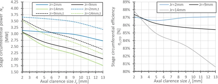
All calculations were performed for the same pressure drop equal to bar. The inlet pressure was preserved constant at the level of , while the live steam fed into the turbine was at a temperature of oC. Numerical analysis included axial clearances mm, while the radial clearances varied mm. In Fig. 3 stage real and theoretical power are presented using real gas and Eulerian models respectively (on the left) and internal (casing) efficiency of the stage (on the right). The resultant casing efficiency in CFD varies between 0.88 to 0.81, which is correct according to the practical knowledge of this turbine’s element.
When analyzing the power results in Fig. 3, it should be stated that the shape of the curves for the powers obtained with the Euler fluid ( ) is similar to the shape of the curves with the real gas model ( ). The mentioned power characteristics depend on the size of the clearances and . However, it should be noted that the magnitude of the axial clearance has a greater influence on the power drop, especially when the radial clearance exceeds 9 mm. The shape of the internal efficiency characteristics is closely related to the powers obtained in Fig. 3a) according to the formula [14]. With clearances and at the level of 2 mm for all curves we obtain a similar value of casing efficiency, namely between 87 and 88%. However, when the axial clearance increases, the values diverge, namely for 2 mm the circumferential efficiency fluctuates at 87%, for 9 mm there is a slight decrease in efficiency, and for 14 mm there is a strong decrease to the value of 80.5% with axial clearance 13 mm.
Figure 3. Circumferential power (left) and internal efficiency (right) of the control stage as a function of clearances dimension.
5. Conclusion
Internal (casing) efficiency of the stage and the entire turbine is the basic criterion in estimating machine perfection, which the manufacturer guarantees before the very first start-up. Since turbine designers are now using both 0D and 3D tools to achieve the best machine performance, the natural question arises of the integrity of efficiencies derived from the two methods. It seems, that three-dimensional models can better (more accurately) determine the flow parameters and hence its casing efficiency.
In this paper the task of comparing the definitions for internal efficiency in zero-dimensional and three-dimensional was undertaken. It turns out that both definitions, aside from real power estimation accuracy, differ substantially in establishing the referential (ideal) powers, to which the real power is then related. Therefore, it is appropriate to speak of polytropic CFD efficiency and isentropic zero-dimensional efficiency as quantities different in the very definitions. Both discussed definitions of
1.50 1.75 2.00 2.25 2.50 2.75 3.00 3.25 3.50 3.75 4.00 4.25 2 3 4 5 6 7 8 9 10 11 12 13 Sta ge circ u m fe re n tia l p o w er Nu [MW]
Axal clarence size Jz [mm]
Jr=2mm Jr=9mm Jr=14mm Jr=2mm,t Jr=9mm,t Jr=14mm,t 80% 81% 82% 83% 84% 85% 86% 87% 88% 89% 2 3 4 5 6 7 8 9 10 11 12 13 Stage ci rcum fe re n tial ef fic ie n cy ηi,CF D [ % ]
Axal clarence size Jz [mm]
Jr=2mm Jr=9mm
© 2021 ISTE OpenScience – Published by ISTE Ltd. London, UK – openscience.fr Page | 9
efficiency in practice give similar results (this is similar to the Puzyrewski equation [16]: if , then both definitions are similar and we can write write .
The standardization of the internal efficiency of the turbine proposed in this article is justified and significant both from a technical perspective, when we are talking about design, and from a scientific perspective, when we introduce a reference between the 0D and 3D approaches. Additionally, the paper shows the influence of axial and radial clearances on the change of power and circumferential efficiency, which is particularly important when designing turbine stages.
Nomenclature
- zero-dimensional - algebraic model of flow based on integral balances of mass momentum, and energy
– three-dimensional model based on differential equations, that requires complete geometry of a flow channel
– blades losses [ ⁄ ]
– internal work losses of a stage [ ⁄ ] – coefficient of theoretical flow capacity – internal efficiency
– volumetric density of a medium [ ⁄ ] – losses :
– time [ ]
– viscous stresses tensor [ ]
– angular velocity vector [ ]
– blade moving area on which medium exerts action [ ] – Computational fluid dynamics)
– absolute velocities at points 0, 1, 2, respectively [ ⁄ ] – medium enthalpy [ ⁄ ]
– axial clearance [ ] – radial clearance [ ]
– theoretical work of a stage [ ⁄ ] – isentropic work of a stage [ ⁄ ]
– polytropic work of a stage [ ⁄ ] – circumferencial work of a stage [ ⁄ ]
© 2021 ISTE OpenScience – Published by ISTE Ltd. London, UK – openscience.fr Page | 10
̇ – mass flow rate [ ⁄ ] ̇ –ideal flow-capacity [ ⁄ ] – mechanical power [ ]
– circumferencial power of a stage [ ] –theoretical power of a stage [ ] – pressure [ ]
–Puzyrewski number (see eqn 19) – pitch radius [ ]
– medium entropy [ ⁄ ] – medium temperature [ ]
velocity normal component [ ⁄ ] – diffusive stresses tensor [ ]
– Umov-Volterra mechanical energy flux [ ⁄ ] [ ] – unit dyadic
– unit normal vector
– turbulent stresses tensor [ ] – radial vector
– blade drift force in 0D model [ ]
– blade drift velocity [ ⁄ ] – fluid absolute velocity vector [ ⁄ ];
Bibliography
[BAD 09] BADUR J., Development of Energy Concept, IFFM PASci, Gdansk, 2009 (in Polish)
[BAD 20] BADUR J., FEIDT M., ZIÓŁKOWSKI P., Neoclassical Navier–Stokes Equations Considering the Gyftopoulos–Beretta Exposition of Thermodynamics. Energies, 13, 1656, 2020; doi:10.3390/en13071656
[BAD 18] BADUR J., FEIDT M., ZIÓŁKOWSKI P., Without Heat and Work - Further Remarks on the Gyftopoulos-Beretta Exposition of Thermodynamics. Int. J. Thermodyn. 21, p. 180–184, 2018; doi:10.5541/ijot.286022.
[CAR 24] CARNOT S., Réflections sur la Puissance Motrice de feu et sur las Machines Propres à développer cette Puissance, Paris Bachelier (1824) (reprod. Ann. Ecole Norm. (2) 1, p. 393-457, 1872, (in French).
[FEI 17] FEID, M., Finite Physical Dimensions Optimal Thermodynamics 1 Fundamentals; ISTE Editions; London; 2017.
© 2021 ISTE OpenScience – Published by ISTE Ltd. London, UK – openscience.fr Page | 11
[GUN 99] GUNDLACH W. R., How much can be earned on the adiabatic efficiency?, Cieplne Maszyny Przepływowe (Turbomachinery), 114, p. 43-64, 1999 (in Polish).
[KAR 04] KARCZ M., Analysis of thermal diffusers in respect to cooling enhancement gas turbine, Research Bulletin IFFM PASci, 535, 2004 (in Polish).
[KOS 07] KOSOWSKI K (Ed.) Steam and gas turbines. Principles of Operation and Design, Alstom, Elblag, 2007
[KOW 17] KOWALCZYK T., ZIÓŁKOWSKI P., SŁAWIŃSKI D., CISAK M., BADUR J., A role of the heat and work
uncompensated transformations in the balance of entropy and the turbomachinery efficiency. Trans. IFFM, 135, p. 11–27, 2017.
[NAS 12] NASTAŁEK L., KARCZ M., SŁAWIŃSKI D., ZAKRZEWSKI W, ZIÓŁKOWSKI P., SZYREJKO C.,
TOPOLSKI J., WERNER R., BADUR J., On the efficiency of a turbine stage; classical and CFD definitions. Trans. IFFM, 124, p. 17-40, 2012.
[PAM 43] PAMBOUR CH.F.M.G., Theorie de la Machine a Vapeur, Paris, 1843: Poggendorff. Annalen, 59, p. 486-492, 1843 (in French).
[PUZ 92] PUZYREWSKI P., One dimensional theoretical basis of fluid-flow machinery, Ossolineum, Wrocław, 1992 (in Polish).
[SAJ 57] SAJŁONOWICZ G., TROJANOWSKI B., Steam turbines, PWN, Warsaw, 1957 (in Polish). [STO 45] STODOLA A. Steam and Gas Turbines, New York, 1945.
[SZE 87] SZEWALSKI R Current problems of energy technology development. Increasing the unit power and efficiency of turbines and power blocks, Ossolineum, Wroclaw, 1987 (in Polish).
[TRA 77] TRAUPEL W, Thermische Turbomaschinen, ed. 3, Berlin, 1977 (in German). [ZEU 98] ZEUNER G.: Technische Thermodynamik, A. Felix, Berlin 1898 (in German).
[ZIÓ 19] ZIÓŁKOWSKI P., BADUR J., ZIÓŁKOWSKI P.J.: An energetic analysis of a gas turbine with regenerative heating using turbine extraction at intermediate pressure - Brayton cycle advanced according to Szewalski's idea. Energy 185, p. 763-786, 2019.