HAL Id: hal-01435994
https://hal.laas.fr/hal-01435994
Submitted on 21 Nov 2017
HAL is a multi-disciplinary open access
archive for the deposit and dissemination of
sci-entific research documents, whether they are
pub-lished or not. The documents may come from
teaching and research institutions in France or
abroad, or from public or private research centers.
L’archive ouverte pluridisciplinaire HAL, est
destinée au dépôt et à la diffusion de documents
scientifiques de niveau recherche, publiés ou non,
émanant des établissements d’enseignement et de
recherche français ou étrangers, des laboratoires
publics ou privés.
An embedded 2D imager for microscale flowmetry based
on optical feedback interferometry
Raul da Costa Moreira, Adam Quotb, Clément Tronche, Francis Jayat,
Antonio Luna Arriaga, Thierry Bosch, Julien Perchoux
To cite this version:
Raul da Costa Moreira, Adam Quotb, Clément Tronche, Francis Jayat, Antonio Luna Arriaga, et al..
An embedded 2D imager for microscale flowmetry based on optical feedback interferometry. IEEE
SENSORS 2016, Oct 2016, Orlando-Florida, United States. pp.1 - 3, �10.1109/ICSENS.2016.7808586�.
�hal-01435994�
An embedded 2D imager for microscale flowmetry
based on Optical Feedback Interferometry
R. da Costa Moreira, A. Quotb, C. Tronche, F. Jayat, A. Luna-Arriaga, T. Bosch, J. Perchoux
LAAS-CNRS, Université de Toulouse, CNRS, INP, F-31400 Toulouse, France
Abstract—We present a compact and embedded imager based
on the Optical Feedback Interferometry (OFI) sensing scheme that gives quantitative information about the velocity in fluids at micro-scale through the Doppler-Fizeau effect. This sensor can reach a spatial imaging resolution up to 5 μm in 2D scanning using a MEMS 2 axis beam-steering mirror. As an illustration of the imager performances, a 500 μm circular channel flow profile is measured. An image (300x50 pixels) of a 100 μm square section channel is successfully obtained thus validating the device.
Keywords—OFI, flowmetry, light scattering, embedded sensing, 2D imager, microscale.
I. INTRODUCTION
The need to develop embedded scanning systems for optical sensing application is a real challenge [1],[2]. As an example, biomedical applications lead scientists to imagine less expensive and more compact systems, either for diagnostic or prognostic uses, or for remote patient care. According to the optical sensing technique and application field, several system configurations can be imagined. In that perspective, we will focus ourselves on laser Doppler flowmeters sensors based on the Optical Feedback Interferometry (OFI) principle.
The OFI arises from the interference inside the laser diode cavity between the electromagnetic wave emitted by the laser and the optical feedback into the cavity due to the back-scattering on a target. This interferometric signal generates variations on the laser output power, carrying sensing information with physical meanings related to the target. OFI sensors present the reat advantage to be naturally extremely compact and self-aligned. In flowmetry applications, the back-scattered wave is subject to a Doppler shift induced by the velocity of the flowing particles [3],[4]. Thus the OFI signals are an image of the velocity distribution inside the sensing volume. [5]
Bulky OFI scanning systems have been proposed [6],[7]. The scanning is usually done by moving the whole sensing system (optics and electronics) across two directions. Such technique provide a high precision and good results, but the scanning time and compactness have to be revised.
In that perspective, a new embedded OFI imager for flowmetry has been realized using a 2 axis beam-steering mirror mounted on Micro-Electro-Mechanical Systems (MEMS) thus taking the full advantage of the compacteness offered by the OFI sensing scheme.
II. OFI SENSING IN FLOWMETRY
In flowmetry applications, an OFI sensor is basically a laser diode with focusing optics pointing onto a channel where particles carried in a flowing liquid back-scatters a part of the laser incident beam towards the laser cavity. For a particle crossing the sensing volume with a velocity VT along the flow
direction, the induced Doppler frequency shift (fD) on the
back-scattered wave is
=2
λ
, (1)where λ is the laser wavelength; n is the refractive index of the fluid and θ is the angle between the laser beam and the normal to the flow direction. In the case of high densities of flowing particles, the photons may be scattered and then Doppler shifted several times. This situation is known as multiple scattering and the resulting OFI signal is a distribution of Doppler shifts.
The amplitude of the OFI signal is proportional to the amount of light reinjected into the laser cavity once backscattered by particles crossing the sensing volume. Such backscattering is related with the power density of illumination, the scattering cross-section of the particles and their optical properties according to the Mie theory.
The main configuration of an OFI sensor involves a laser diode as the coherence light beam source with a built-in photodiode inside its package. The photodiode is located behind the laser’s cavity enabling the acquisition of the power variations induced by the interferences inside the laser’s active cavity. Optical components, such as lens or mirrors, can also be included in an OFI sensor to properly guide and shape the laser beam on the target according to the application. Besides that, electronic circuitry is required to drive the laser, and exploit the interferometric signal. Eventually OFI signals are filtered and amplified before proper digital signal processing.
To the best of our knowledge, the OFI scanning devices depicted in the literature have been realized with big and heavy mechanical systems that require much physical space and scanning time[6],[7]. The great novelty of our present solution is the use of a fast MEMS mirror for 2D scanning. The compactness of the MEMS mirror allows designing an embedded imaging system in a compact handheld case.
The signal processing implemented to exploit the sensing information is based on the spectral analysis of OFI signals in the case of the multiple scattering regime. The mean Doppler
frequency (f ‘D) is derived from the 1st weighted raw moment
[4],[6],[7]–[10] as
= . ( )
( ) , (2) where fmin and fmaxset the spectral frequency range and P(f) is
the amplitude of the power spectral density (PSD). III. 2D SCANNING SETUP FOR MICROFLUIDICS
The OFI embedded device represented in the Fig. 1a has been designed to be able to provide a 2D image with quantitative information of the local velocity in microfluidics applications.
Fig. 1. (a) CAD design for the cases (base and handheld imager) with CATIA. (b) Photography of the 1st prototype for the handheld part (made on a
3D printer).
The hardware solution of the system was designed and packaged in two parts: the handheld part (Fig. 1b), that includes the OFI sensor itself with the complete optical solution, the laser and related driving and signal amplification boards; and the base, that provide power supply and interface the handheld sensing system with the PC. The base includes an ADC acquisition card (National Instruments NI-6361 USB OEM) with an interface board for cabling. The handheld and base devices are connected through a 1.5 m 14-wire cable.
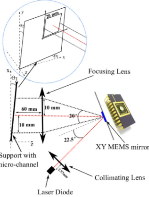
The system embedded in the handheld part is detailed in Fig. 2. It is constituted of: a DFB laser diode (Mitsubishi ML725B11) lasing at λ=1310 nm, packaged with a monitoring photodiode; custom made laser driver and photodetected signal amplification circuit; a collimating lens (Thorlabs C660TME-C) is placed in front of the laser to fit and keep the beam width along the optical path and onto the circular aluminium coated mirror (Mirrorcle S4417) of diameter 4.2 mm. A focusing lens (Thorlabs AC254-060-B-ML) is placed at its focal length from the target to focus the beam. The maximum possible area to scan is 20 x 20 mm limited by the scanning lens working dimension.
The MEMS beam steering mirror presents an angle range of -5° to +5° in each direction (X/Y), which corresponds to -10V to +10V for the analog inputs of its driver board. The MEMS commands are generated by the ADC card through a custom Labview VI.
The maximum scanning resolution is limited by the minimum voltage step (5mV) achievable at the ADC output
leading to a step angle of 0.0025°, which implies a maximum resolution of 5 μm. The complete signal processing is written with Matlab and the code is embedded in the Labview VI. The graphical user interface allows configuring the rasterisation parameters.
Fig. 2. 2D scanning system embedded in the handheld part. The red dot line indicate the laser path with the mirror centered at X=Y=0°. The two others in black indicate the path in the extremes of the angular range of the mirror.
IV. EVALUATION OF THE IMAGER PERFORMANCES
In order to validate the sensor, two main experiments have been performed. In the first one, a transparent plastic tube of 500 µm inner diameter was chosen as target. The tube is located at the working distance with θ1=0 and θ2=7.5° (see Fig.
2). The fluid injected in the tube by a syringe pump is full milk. For the acquisition of the flow profile, 3 lines (in Y) spaced by 8.33 µm of 60 points (in X) have been scanned across the channel. The Fig. 3 shows the measured (mean of the 3 lines) flow profile for the milk pumped at a rate of 50 µL/min. It reveals a laminar flow regime fitting well the Hagen-Poiseuille profile [11] for a Newtonian fluid.
Fig. 3. 50μL/min flow profile measured (with fitting curve)
In the second experiment, a full 300x50 pixel image is acquired in order to better evaluate the scanning resolution and the related trade-off with the scanning time. For this setup, a micro-channel (Fig. 4) made in SU8-photoresist using
(a) (b)
Handheld imager
Base
Channel - X position (point)
0 10 20 30 40 50 60
1st weighted raw moment (Hz)
200 400 600 800 1000 1200 1400 1600 Flow Profile measured velocity Hagen-Poiseuille fitting Support with micro-channel
photolithography was designed. This time θ1=3° and θ2=7.5°
(Fig. 2), as both are necessary in order to obtain the Doppler effect depicted in (1) across the curved sections of the serpentines.
Fig. 4. (a) Photo of the 100 μm micro-channel with serpentines. (b) CAD design for for the 100 μm micro-channel done with CLEWin5.
As a result of the second experiment, the Fig. 5 shows the 2D Doppler image of a part of serpentine of the micro-channel where full milk is pumped at a flow rate of 10 μL/min. The scanning resolution in the X direction is ~5.8 μm, and ~25 μm in the Y direction. These values were chosen to show the minimal spatial resolution in X but with a larger step in Y not to compromise too much the scanning time.
As can be seen on Fig. 5, the imager is able to discriminate the different channels until the very last step of the serpentine where the gap between each channel is only 10 µm.
The main parameters that limit the scanning speed are: the time of acquisition for each point and the interval between each acquisition. This interval was set according to the MEMS mirror datasheet at 50 ms to ensure that the mirror is stabilized before starting the acquisition. The time of acquisition is defined by the sampling rate (set at 1 MHz), and the number of samples (set at 409.600) for each point. The scanning of the 15.000 points for this Doppler image took 185 minutes. However diminution of this sample number is now under study since it is clearly the major timing constraint for a faster scanning.
Fig. 5. 2D Doppler image (300x50 pixels) of a part of the serpentine 100x100µm channel.
V. CONCLUSION AND FUTURE WORKS
An innovating device based on the association of an OFI sensor with a two-axis point-to-point beam-steering mirror is
presented in this work. It is demonstrated to allow the design of an OFI 2D Doppler imager that is extremely compact.
Regarding the state of the art on OFI embedded sensors for flowmetry, this device presents an important improvement for its compactness and its scanning time despite this last characteristics is still to be improved.
Future works is now ongoing on the signal processing to reduce the number of acquired samples, improving considerably the scanning time, but also to enhance the robustness against mechanical noises when the measurement is done while handling the imager.
These further improvements of the device shall enable application in vivo for various non-invasive biomedical applications related with flowmetry such as blood perfusion under human skin.
ACKNOWLEDGMENT
This work was partly supported by LAAS-CNRS micro and nanotechnologies platform member of the French RENATECH network.
We are grateful to E. E. Ramírez-Miquet for manufacturing the 100 μm square micro-channel at LAAS-CNRS.
REFERENCES
[1] J. David Briers, “Laser Doppler, speckle and related techniques for blood perfusion mapping and imaging,” Institute of Physics Publishing Physiol. Meas. 22 (2001) R35–R66.
[2] A. Humeau, W. Steenbergen, H. Nilsson,and T. Stromberg, “Laser Doppler perfusion monitoring and imaging:novel approaches,” Med. Bio. Eng. Comput. (2007) 45:421–435.
[3] M. Norgia, A. Pesatori, and L. Rovati,“Self-mixing Laser Doppler: a Model for Extracorporeal Blood Flow Measurement,” IEEE, 2010. [4] M. Norgia, A. Pesatori, and L. Rovati, “Optical Flowmeter for Blood
Extracorporeal Circulators,” IEEE, 2009.
[5] C. Zakian, M. Dickinson and T. King, “Particle sizing and flow measurement using self-mixing interferometry with a laser diode,” IOP, Journal of Optics A: Pure and Applied Optics, Volume 7, Number 6, 2005.
[6] C. Zakian and Mark Dickinson,“Laser Doppler imaging through tissues phantoms by using self-mixing interferometry with a laser diode,”Applied Optics,Vol. 32, No. 19, October 1, 2007
[7] A. Quotb, E. E. Ramírez-Miquet, C. Tronche, and J. Perchoux,“Optical Feedback Interferometry sensor for flowcharacterization inside ex-vivo vessel,” IEEE, 2014, pp. 362–365.
[8] F.F.M. de Mul, M. H. Koelink, A. L. Weijers, J. Greve, J. G. Aarnoudse, R. Graaff, and A. C. M. Dassel, “A semiconductor laser used for direct measurement of the blood perfusion of tissue,” IEEE transactions on biomedical engineering, vol. 40, no. 2, February 1993.
[9] F. F. M. de Mul, M.H. Koelink, A. L. Weijers, J. Greve, J. G. Aarnoudse, R. Graaff, and A. C. M. Dassel, “Self-mixing laser-Doppler velocimetry of liquidflow and of blood perfusion in tissue,” Applied Optics, Vol. 31, No. 27, 20 September 1992.
[10] J. R. Tucker, J. L. Baque, Y. L. Lim, A. V. Zvyagin, and A. D. Rakic, “Parallel self-mixing imaging system based on an array of vertical-cavity surface-emitting lasers,” Applied Optics, Vol. 46, No. 25, September 2007.
[11] L. Campagnolo, M. Nikolic, J. Perchoux, Y. L. Lim, K. Bertling, K. Loubière, L. Prat, A. D. Rakic, and T. Bosch, “Flow profile measurement in microchannel using the optical feedback interferometry sensing technique,” Microfluid Nanofluid (2013), 14:113–119. Pixel (5,8 um/pixel)
Pixel (25 um/pixel)
(a) (b) 1400 um 10 um