Publisher’s version / Version de l'éditeur:
Vous avez des questions? Nous pouvons vous aider. Pour communiquer directement avec un auteur, consultez la première page de la revue dans laquelle son article a été publié afin de trouver ses coordonnées. Si vous n’arrivez pas à les repérer, communiquez avec nous à [email protected].
Questions? Contact the NRC Publications Archive team at
[email protected]. If you wish to email the authors directly, please see the first page of the publication for their contact information.
https://publications-cnrc.canada.ca/fra/droits
L’accès à ce site Web et l’utilisation de son contenu sont assujettis aux conditions présentées dans le site
LISEZ CES CONDITIONS ATTENTIVEMENT AVANT D’UTILISER CE SITE WEB.
Research Paper (National Research Council of Canada. Division of Building
Research), 1973-01
READ THESE TERMS AND CONDITIONS CAREFULLY BEFORE USING THIS WEBSITE. https://nrc-publications.canada.ca/eng/copyright
NRC Publications Archive Record / Notice des Archives des publications du CNRC :
https://nrc-publications.canada.ca/eng/view/object/?id=a2300a41-2fe9-4d0b-ad1d-829f9b0fd074
https://publications-cnrc.canada.ca/fra/voir/objet/?id=a2300a41-2fe9-4d0b-ad1d-829f9b0fd074
NRC Publications Archive
Archives des publications du CNRC
This publication could be one of several versions: author’s original, accepted manuscript or the publisher’s version. / La version de cette publication peut être l’une des suivantes : la version prépublication de l’auteur, la version acceptée du manuscrit ou la version de l’éditeur.
For the publisher’s version, please access the DOI link below./ Pour consulter la version de l’éditeur, utilisez le lien DOI ci-dessous.
https://doi.org/10.4224/40000447
Access and use of this website and the material on it are subject to the Terms and Conditions set forth at
Experimental determination of structure and foundation parameters
using wind-induced vibrations
7531
Experimental determi nation of structure
and foundation parameters using
wind-induced vibrations
H. S. WARD, BSc, PhD, M I C E
J. H.
RAINER,
P ~ DReprinted from Proc. lnstn Civ. Engrs, 1972, 53 (September) 305-322
0
The Institution of Civil Engineers, 1972T h e I n s t i t u t i o n o f Civil Engineers G r e a t G e o r g e S t r e e t , London, S . W , l
7531 Experimental determination of structure
and foundation parameters using
wind-induced vibrations
H. S.
W A R D , BSc. P ~ D , MICE'J.
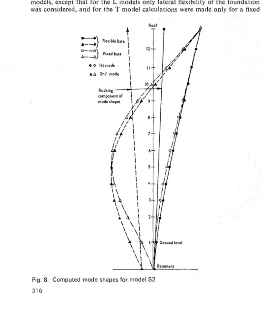
H.
RAINER, hotWind-induced vibrations in multi-storey buildings are utilized to determine foundation stiffnesses as well as structural modal properties. Two methods are presented which permit the determination of foundation stiffnesses, both rocking and in the horizontal direction, by combining experimental data with theoretical calculations. One hod employs modal frequency ratios for the entire system; the other employs dal amplitude ratios. A quantitative assessment of the restraint on a large raft ndation of a 12 storey reinforced concrete building is given.
Introduction
Whenever the theoretical prediction of the behaviour of a large civil engineering system such as a multi-storey building or d a m is compared with actual perform- ance, it is not unusual t o find discrepancies between prediction a n d
Frequently the causes of the discrepancies are known, but because of a lack of quantitative data on, for example, the characteristics of certain structural loads o r the stiffening action of partitions a n d curtain walls, they have generally been ignored in the design or accounted for by gross approximations. Some of these uncertainties could be resolved by full-scale structural testing, but there has been reluctance t o undertake this because until recently it represented a tremendous task. However, in the past few years, methods have been deve- loped which provide quick a n d simple means of testing a structure. Generally speaking, they involve measuring vibrations generated by mechanical r n e a n ~ ~ - ~ or by a natural cause such a s wind or earthquake."-lo
2. The main object of this Paper is to show that such test methods a r e effective in investigating the elastic behaviour of large structures. The example used in the study is a 12 storey structure built on a raft foundation, in turn supported by a deep layer of clay. Experimental a n d theoretical results are interpreted i n a way that identifies the stiffness characteristics of the soil a n d the structure.
The problem
3. As information has been accumulated about the response of structures t o earthquakes it has been shown that ground-structure interaction niay play a n important role.ll-l3 I n simple terms the interaction phenomenon repre- sents the boundary condition imposed by the soil on structural movements; this may vary from a n almost fully fixed base condition for a rock or till t o a fairly flexible support for clay.
4. Numerous theoretical studies have been made of the dynamic character- Written discussion closes 15 November, 1972 for publication in Procerditrgs, Part 2.
*
Formerly Division of Building Research, National Research Council of Canada, now University of Technology, Loughborough.W A R D A N D R A I N E R
Fig. 1. Aerial view of Public Service Alliance of Canada building, Ottawa
istics of foundation e l e i ~ ~ e n t s . l ~ - ~ ~ Experimental work 11as been carried out, in some instances to substantiate the theoretical worklg and in others to investigate the properties of the soi1.20~21 Mainly in response to the impetus provided by earthquake engineering requirements, there has been a logical extension from the theoretical study of a foundation element on a soil to the coupling of a foundation and superstructure to the ~ o i l . ~ " , ~ ~ If the soil impedance, or the resistance of the soil to the nlovement of the foundation element as a function of frequency, were known there would be no difficulty associated with this coupling process. However, with current knowledge it is difficult to predict soil impedance and experimental data are required to develop this capability. In Japan earthquakes have been used to obtain information on foundation behaviour at the associated high stress levelsz4 and related work at much lower stress levels has been reported from a building excited by a mechanical v i b r a t ~ r . ~ ~ ~ ~ ~ The aim of the work reported in this Paper was to discover whether wind excitation could be used in investigating ground-structure interaction, and thereby to arrive at quantitative structural and foundation properties.
S T R U C T U R E A N D F O U N D A T I O N P A R A M E T E R S
Shearwalls with 12" elements Per~meter wall, glaz~ng O u t l ~ n e o f raft foundation and 4" brick I
.
.
.
I . ..
8 I I 24" x 2):' L---
- -
----
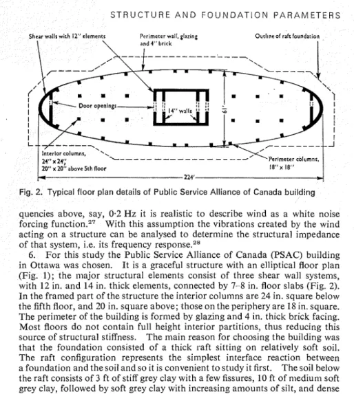
Pertmeter columns, 20" x 20" above 5th floor 224'Fig. 2. Typical floor plan details of Public Service Alliance of Canada building quencies above, say, 0.2 Hz it is realistic to describe wind as a white noise forcing function.27 With this assumption the vibrations created by the wind acting on a structure can be analysed to determine the structural impedance of that system, i.e. its frequency response.28
6 . For this study the Public Service Alliance of Canada (PSAC) building
in Ottawa was chosen. It is a graceful structure with an elliptical floor plan (Fig. 1); the major structural elements consist of three shear wall systems, with 12 in. and 14 in. thick elements, connected by 7-8 in. floor slabs (Fig. 2). In the framed part of the structure the interior colu~nns are 24 in. square below the fifth floor, and 20 in. square above; those on the periphery are I8 in. square. The perimeter of the building is formed by glazing and 4 in. thick brick facing. Most floors do not contain full height interior partitions, thus reducing this source of structural stiffness. The main reason for choosing the building was that the foundation consisted of a thick raft sitting on relatively soft soil. The raft configuration represents the simplest interface reaction between a foundation and thesoil and so it is convenient to study it first. The soil below the raft consists of 3 ft of stiff grey clay with a few fissures, 10 ft of niediurn soft grey clay, followed by soft grey clay with increasing amounts of silt, and dense till at 50 ft. The water content of the clay was generally 70%, and its undis- turbed vane test shear strength was typically 1.5 kip/sq. ft.
Measurement and analysis o f vibrations
7. The building vibrations were recorded on four occasions when there was a minimum of vibration from street traffic and internal sources such as lifts. Willmore Mk I1 seismometers, adjusted to flat velocity response for frequencies above 0.5 Hz were used to detect the vibrations.
8. Generally, six seismometers were strung out in the building and their outputs recorded on a seven track F M tape recorder; at least one measuring point was common to successive sets of recording sessions. During the recording sessions the wind speed rarely exceeded 15 mile/h, except when a brief storm affected the end of one set of records.
W A R D A N D R A I N E R
already been p r e ~ e n t e d . ~ . ~ , ~ Rocking data for the raft foundation were obtained from sinlultaneous vertical vibration measurements taken near the centre a n d a t the outer wall of the basement. The fundamental objective of the analysis is t o determine the a ~ t ~ p l i t u d e of the vibrations o n each floor level as a function of frequency, a n d the phase relations between these ampli- tudes o n different floor levels.
10. In the past these objectives have been carried out using analogue frequency analysis equipment5 o r Fourier analysis techniques o n digital c ~ n i p u t e r s . ~ I n this study a real-time frequency analyser was used. T h e time required for analysis is thereby drastically reduced a n d the use of ambient vibration measurements for evaluating structural characteristics becomes more attractive.
Results
Experimental results
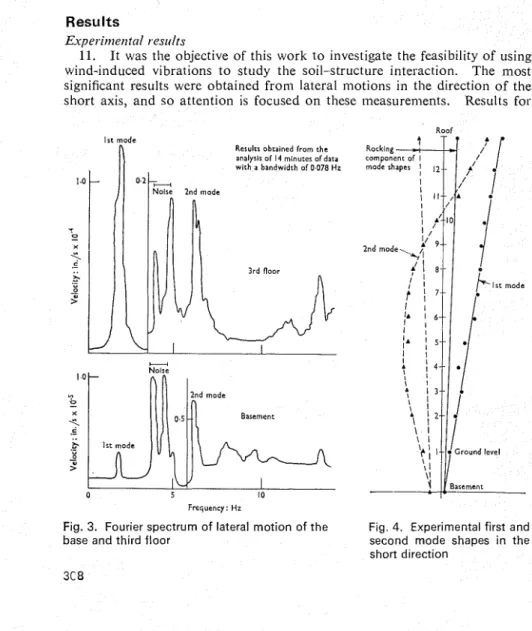
11. I t was the objective of this work t o investigate the feasibility of using wind-induced vibrations t o study the soil-structure interaction. The most significant results were obtained from lateral motions in the direction of the short axis, a n d s o attention is focused o n these measurements. Results for
Irc mode
Results obra~ned from the analyrls of 14 mtnuter ofdata wtth a bandwddth of 0 078 Hz I .o T 0 - X
5
k - J mode Basement%
Frequency: HzFig. 3. Fourier spectrum of lateral motion of the Fig. 4. Experimental first and
base and third floor second mode shapes i n the
S T R U C T U R E A N D F O U N D A T I O N P A R A M E T E R S lateral niotion along the long axis and torsional inodes of vibration are also tabulated t o provide further confidence in the theoretical fornii~lation for the superstructure.
12. The Fourier analyses of simultaneous records of lateral motion along the short axis, o n the third floor a n d in the basement are shown i n Fig. 3. The basement record shows one of the difficulties with measuremeilts of this kind, namely the presence of 'noise' from other sources of excitation such as traffic or mechanical equipment.
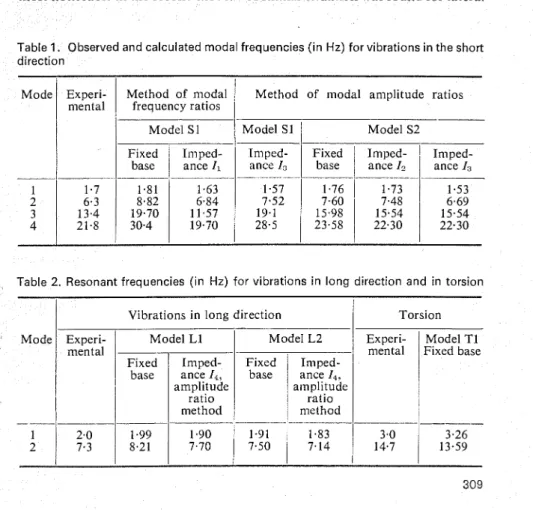
13. The first four modes of vibration for lateral inotion along the short axis of the building were found and the first two mode shapes are reproduced in Fig. 4. Table 1 shows the experimental values of the four lowest resonant frequencies. The first two mode shapes and frequencies of vibration for lateral inotion along the other axis of the building and for torsional movements were also derived. Frequency values are shown in Table 2.
14. F o r lateral ~noveiuents in the short direction of the building there was a significant rocking motion in the fiindameiital mode, but this component was less noticeable in the higher modes. Expressed as a percentage of the inaxi- inurn displacement in a given mode, the horizontal movement of the base was most noticeable in the second mode.
A
similar situation was found for lateralTable 1. Observed and calculated modal frequencies (in Hz) for vibrations in the short direction
Mode Experi-
mental Method of modal frequency ratios
/
I
Method of modal amplitude ratiosI I I I I I I
Table 2. Resonant frequencies (in Hz) for vibrations in long direction and in torsion Model S1
Fixed 11iiped- base
1
ance I ,-- -- -- -- -
Model Sl
/
Model S2Irnped- Fixed Impcd- Iniped- ance I3
1
base1
ance I. ance &- - -- . - --
Mode
- -- -
1 2
Vibrations in long direction Experi-
I
L1 mental - Fixed b a sIniped- e T amplitude ratio method -- Torsion Model L2Fixed base ance Iniped- I*,
amplitude ratio method Experi- mental - -1.91 3.26 7.50
1
7.14""
1
1 13.59 Model T1 Fixed base -- -- 2.0 7.3 1.991
1.90 8.21 7.70WARD AND RAINER
Table 3. Experimental damping values, per cent of critical
movements i n the long direction. Although rocking movements i n this direc- tion were not measured, they tend t o be small because of the great length of the raft foundation. I n the torsional modes it was possible t o detect a small amount of rotational movement i n the base a t the fundamental frequency, but there was n o rotational movement a t the second mode frequency.
15. A n estimate of the equivalent viscous d a n ~ p i n g characteristics of the modes of vibration can be obtained by measuring the half-power bandwidth of the power spectrum. T h e results obtained from the experimental measure- ments by this method are given in Table 3. The resolution of the d a n ~ p i n g measurements is determined by the analysis bandwidth, and in this study the resolution was of the order of 2% for fundamental modes, 0.5% for second modes a n d 0.2% for third modes.
16. Many previous measurements of damping obtained in this manner have been much ~ m a l l e r , ~ - ~ but the structures studied were founded o n fairly rigid ground. I t is probably reasonable t o attribute a t least part of these higher d a n ~ p i n g values t o the geometric or radiation d a n ~ p i n g of the soil. There was n o significant variation of half-power bandwidth through the height of the structure, for a given mode analysis procedure produces a n average value of damping for the whole system.
Theoreticrrl resirlts
17. T h e interpretation of the experimental data was supported by theoreti- cal analysis of the structure-foundation system. The procedure was t o calcu- late the modal characteristics of a superstructure model in combination with a range of foundation i n ~ p e d a n c e s ~ ~ and thus t o identify the combination that gave the best match between calculations a n d observations. T w o methods of analysis are considered. The first is based o n a comparison of measured and computed ratios of the modal frequencies; this is called the method of modal frequency ratios. The second method compares measured a n d computed mode shapes, or more specifically the ratios of base t o t o p storey deflexions; this is called the method of modal amplitude ratios.
18. There is little variation in the resonant frequency of a system f o r low values of damping. F o r simplicity, zero d a n ~ p i n g was assumed in the theoreti- cal calculations although it would be possible t o incorporate any value of proportional damping. It was also assumed t h a t the soil properties were amplitude-independent.
Torsion 7.1 1.3 Mode
1
Short directionI 5.2
2 3
Modal frequency ratios
Long directioll 5.8 1.2
19. T h e first method of analysis is based o n the supposition that the struc- ture can be represented adequately by a particular mathematical model, i.e.
S T R U C T U R E A N D F O U N D A T I O N P A R A M E T E R S t geometric properties and density and stiffness distributions are well ablished. Although the absolute values of the resonant frequencies of such structure will depend on actual material properties, such as density and Young's modulus, the ratios of higher order frequencies to the fundamental
ncy are invariant relative to these two properties.
.
This fact was used by assuming an appropriate superstructure model considering the effect of allowing the foundation support condition to.
A plot could thus be drawn of the frequency ratios as a function of dation stiffness. If a match could be obtained for the experimental and eoretical ratios then a true definition of the combined system would have een achieved and the value of the foundation impedance determined. The upper and lower bound could be established for the absolute values of the frequency by specifying reasonable values for the n~odulus of concrete and theeight of the building.
21. The end shear walls and central core were assumed to be cantilevers th flexural and shear flexibilities taken into account. The columns and part the slabs were treated as frames and were assumed to be connected to the cantilevers by rigid diaphragm action of the floor slabs. Along one side of the building there were two levels of underground parking, but this portion was separated by a construction joint from the main structure and thus it was assumed that there was no interaction between the two structures.
22. T o differentiate between the various structural models S is used to designate the model assumed for lateral vibrations in the short direction of the building, L that for lateral vibration in the direction of the long axis and T that for torsional vibrations. The full flexural stiffness of the cantilevers and column bents was used for models S1 and L1. The shear resistance of the walls was based on a uniform shear stress distribution over the walls. Another pair of models, S2 and L2, representing second approximations, was developed at a later stage of the study. Model T1 represents the torsional resistance due to the end shear walls, column bents and core.
23. As far as the superstructure is concerned the action of the soil imped- ance is to introduce an extra six degrees of freedom at its base. As the struc- ture under consideration is nominally synln~etrical about both orthogonal axes, it was assumed that there was no coupling between the lateral displace- ments of the two principal directions. Thus each degree of freedom of base motion could be considered independently and modelled by a simple spring. Only the horizontal base movements in the long and short direction and rock- ing in the short direction were considered in detail.
24. The design drawings specified that concrete strength in the colun~ns and shear walls should be 5000 Ibjsq. in. below the second storey level and 4000 lbjsq. in. above the second floor. In the calculations, Young's modulus for the concrete in these areas was taken to be 3.9 x loG lbjsq. in. and 3.3 x 10G lbjsq. in., respectively. The corresponding shear moduli were taken as 1.5 x lo6 lbjsq. in. and 1.3 x lo6 Ibjsq. in. It was assumed that the density of the concrete was 150 lbjcu. ft and all floor weights above the ground floor were taken as equal. The rotational moment of inertia of the raft and the floor slabs was also considered in the equation of motion involving the rocking of the building. The nominal values for the physical properties of the super- structure were used in the theoretical caIculations, but they influence mainly the absolute values of the frequencies rather than the frequency ratios.
W A R D A N D R A I N E R
1st mode
+~k
3rd modeo F,
.
4th mode
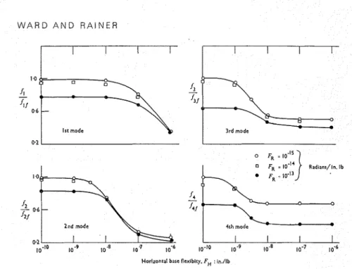
Fig. 5. Theoretical frequency reduction, relative to fixed base frequency, due to base flexibility-model S1
25. Some of the theoretical calculations for the model S I are shown in Fig. 5 ; here for each mode i the variation of frequency is shown for a range of foundation flexibilities. F o r comparison the data are plotted a s ratios of modal frequencyf, t o the fixed base frequencyf,,. The v a l ~ ~ e s off,, are shown in Table 1 and with these data f , can be evaluated from Fig. 5. I n Fig. 5 the base flexibility has a n earlier influence o n the higher modes, e.g. the base flexibility FII of l o - @ in./lb has scarcely influenced the fundamental mode, but there has been a significant change inJi when F,, is only in./lb. Another feature, which is general for the sort of structure-foundation model under consideration, is the continuous decrease in the fundamental frequency a s ground flexibility increases, whereas the higher mode frequencies tend t o approach an asyn~ptotic value.
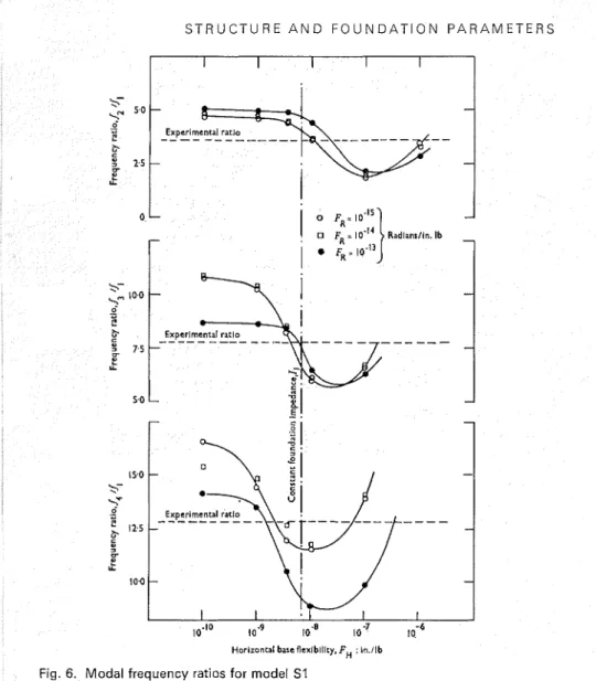
26. When the data are expressed in terms of modal frequency ratios, as in Fig. 6, the influence of base flexibility is again evident. Here it is possible t o plot the experilnentally observed modal frequency ratios, and thus t o infer the foundation impedance from the intersection between the calculated a n d experimental curves. If it is postulated that the foundation impedance is independent of frequency, then the vertical dotted line in Fig. 6 probably represents the best choice for constant foundation parameters. Thus if
F,, is taken as 8 . 0 ~ in./lb and the rotational spring flexibility Fl% is 1 x 1 0 - l 4 rad/in. lb, the errors between the theoretical a n d experimental ratios of fi/fi, f3/fl and fi/fi are approximately
+
13"/,, - 10% a n d - 6% respectively.These values of FH and FR comprise the foundation impedance designated Il. 27. A plot similar t o that in Fig. 6 but with the rotational flexibility Fn
Fig. 6. Modal frequency ratios for model S1
plotted on the abscissa, a n d for various values of liorizontal flexibilities F,,, enables one to esti~iiate the v a l ~ ~ e of F, as 1 x 10-l4 rad/in. lb. However, since the frequency ratios are less sensitive t o FR than t o Fcl, the intersections of the theoretical curves with the experimental frequency ratio are less well defined, a n d therefore the value of FR obtained by this method is less precise than that for F,,.
28. It is apparent that even better agreement could be achieved if the foun- dation impedance were assumed t o vary with frequency. Thus if it is assumed that FR remains constant at 1 x 10-l" rad/in. lb, the experimental results cross the theoretical curves for the ratios
&If,,
f . j / f , a n d f,/f, a t values of F,, whichW A R D A N D R A I N E R
are 1.0 x 8.0 x and 5.0 x in./lb, respectively. This suggests a foundation stiffness that increases with frequency. If the values of FI, and
FR are assumed to vary, then the possible range of foundation values becomes
broader, although the choice for FH would still be confined to a relatively small area.
29. The nature of the curves in Fig. 6 means that there is a n ~ i n i ~ n u ~ n point in the frequency ratio curves beyond which the ratios increase as the foundation flexibility increases. This means that the experimental results cut the theoretical curves a second time. In this instance this takes place for values of F, between and in./lb. Although this region leads to correct values for the frequency ratios it can be dismissed from further con- sideration because the absolute values of the frequencies are much lower than the measured ones.
30. I11 the method described so far the use of frequency ratios nlakes it possible to minimize the influence of the s t r ~ ~ c t ~ l r a l properties in determining foundation characteristics. It is nevertheless instructive at this point to calcu- late the absolute frequencies corresponding to the foundation paranleters just deduced (inipedance 11) and to compare them with the observed frequencies. Coniparison of the second and fourth colunins of Table 1 shows that the frequencies agree within 10-15%, which seems adequate in view of the approxi~nations in the initial assunlptions about the superstructure.
M o d a l amplitude ratios
31. In the previous calculations it has been assumed that the only unknown factor is soil impedance. However, if the mathematical model of the structure is not precisely established, or for reasons of economy it is approxiniated, the method of modal amplitude ratios enables one to obtain foundation stiffnesses as well as progressive improven~ents in the structural idealization. The method uses comparisons of measured and calculated mode shapes of the structure as well as the modal frequencies.
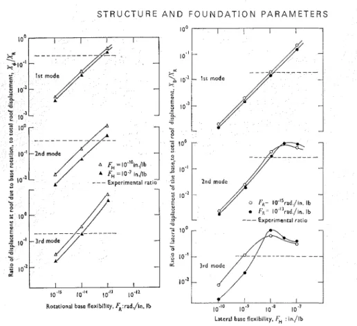
32. As the mode shapes of a structure serve the sanle purpose as the frequency ratios in defining the behaviour of the system, characteristics of the modal deformations can also be used to find foundation stiffnesses. The procedure consisted of taking a superstructure model and calculating the mode shapes for different values of the lateral and rotational base flexibilities. The ratio of roof to base deflexion is used as an index of mode shape and is called the modal amplitude ratio. For each particular mode, this ratio was plotted as a function of the foundation properties. From corresponding experimental data it is possible to choose foundation values that provide agreement between the experimental and theoretical modal amplitude ratios. With these founda- tion values it is possible to calculate the frequencies of vibration and compare tliern with the experimental values.
33. Calculations using model S l showed an improvement in the agreement between theory and experiment when the shear resistance of the superstructure was decreased. This form of modification appears justified on account of the door openings in the shear walls, originally not considered. Furthermore, shear stress distribution across a member is in general not uniform, as was originally assumed in model S1. An increase of shear flexibility of 50% in the cantilever walls led to model S2, for which the results of the amplitude ratio plots for the first three modes are shown in Fig. 7. The foundation movement
S T R U C T U R E A N D F O U N D A T I O N P A R A M E T E R S
Fig. 7(a). Rotational amplitude ratios for model S2
Lateral base flexibility. FH : in./lb
Fig. 7(b). Translational amplitude ratios for model 5 2
in the f o ~ ~ r t h mode could not be measured accurately a n d so it is not plotted here; its modal frequency was c a l c ~ ~ l a t e d using the foundation stiffnesses found for the third mode. Again the indications are that a frequency-dependent soil impedance is required t o obtain agreement between theory and experiment, and this dependency appears t o be a n increase in foundation stiffness with frequency.
34. The results in Figs 5-7 were calculated o n the basis of a given constant value of foundation flexibility for all modes of vibration. I n order t o continue the procedure described it is necessary t o consider the implications of allowing the foundation parameters t o take o n the values suggested by the experimental results.
35. Although it is possible t o handle a frequency-dependent foundation condition by evaluating the transfer function of the structure and soil combined, a simpler solution is t o consider that for each nlode the s u p e r s t r u c t ~ ~ r e is connected t o the corresponding foundation impedance f o ~ ~ n d in Fig. 7. Thus the foundation values that give the best agreement for the fundamental mode were used t o calculate only the fundamental mode and frequency of the com- bined system. Similarly, the foundation values for the second a n d third modes
W A R D A N D R A I N E R
found from Fig. 7 were used t o compute the lnodal properties for the second and third modes, respectively. A rigorous proof for the validity of this ap- proach was not sought, but some calculations comparing the transfer function approach with the simpler method show that there is little error near the resonant frequency ~ ~ n d e r consideration.
36. The calculated shapes of the first two modes for model S2, based o n agreement between mode shape ratios, are shown in Fig. 8 ; the mode shapes for the S2 model attached t o a rigid base are also given. If these theoretical mode shapes are compared with the corresponding experimental results there is good agreement in the major details. The same procedure was followed in relating the theoretical a n d experimental amplitude ratios for the L a n d T models, except that for the L lnodels only lateral flexibility of the foundation was considered, a n d for the T model c a l c ~ ~ l a t i o n s were made only for a fixed
Fig. 8. Computed mode shapes for model S2 31 6
S T R U C T U R E A N D F O U N D A T I O N P A R A M E T E R S base condition. For similar reasons (as for the short direction) the shear flexibility in model L2 was increased by 30% over that assumed in model Ll. Detailed results are not presented for this case, although the lateral foundation stiffness derived is denoted by impedance I, in Fig. 9.
Fousidation parameters and resonant frequencies
37. An overall impression of the main features of the results may be ob- tained by showing the nature of the foundation impedances that were suggested by the theoretical work, together with the agreement between the experimental and theoretical values for the resonant frequencies of the structure-ground interaction system.
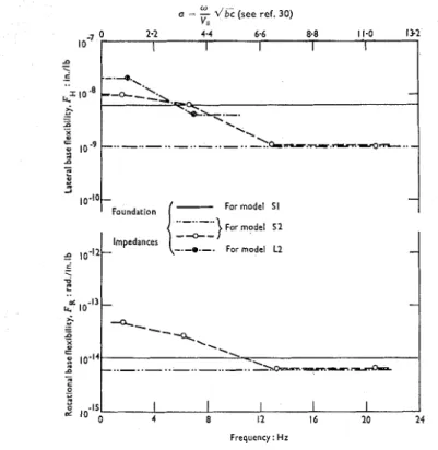
38. The various values of foundation flexibility derived from matching experimental and theoretical results are given in Fig. 9. The foundation impedance I , is the constant base flexibility model derived from the modal frequency ratio method for model S l (Fig. 6).
I2
is an arbitrarily selected constant foundation impedance for model S2, intended to give close agreement between measured and con~puted values of the fundamental frequency. I, is the foundation impedance for model S2, obtained from the modal amplitude ratio in Fig. 7, and I, is the impedance obtained for the model L2 in the longo =
"
d B (see ref. 3 0 )v*
Frequency: Hz
For model 5 1
Fig. 9. Foundation impedances based o n measurements and calculations
9 1o-I1-- -
.
B kd 10-I'.s
- - 9C
10-14 a - 0 - u2
Impedances---
-.-a,-. For model L2
-
- - -,
--
-.
.
.
\-.
-
.- ..-..-..-.. -ho=-7.--- I I I I I 4 8 I2 I 6 1 0 24W A R D A N D RAINER
direction of the building. I ~ n p e d a n c e s Z3 a n d
4
show a decrease in foundation flexibility or, conversely, a n increase in foundation stiffness, a s a function of frequency. I n addition t o the frequency values on the abscissa scale, the values of the characteristic non-dimensional frequency n, used in previous experin~en- tal a n d theoretical s t ~ d i e s , ~ ~ . ~ ~ . ~ ~ a r e shown for a n assumed shear wave velocity of 800 ft/s in the ground. This might be the basis for comparing the results with those obtained from small-scale footing tests.39. Table 1 summarizes all the information o n the resonant frequencies of vibration for the S models. T h e frequencies in the fourth, seventh a n d eighth columns agree reasonably well with the experimental values, but it is apparent that the 52 model with a soil impedance between I, and Id could lead t o agreements for the first four frequencies of vibration that are better than f 15%. This is considered t o be better agreement than that obtained in the modal frequency ratios calculations because with the f 15% agreement in frequency there is also good agreement between mode shapes.
40. Table 2 compares experimental and computed frequencies for lateral vibrations in the long direction of the building a n d for torsional vibrations. Only the first two modes of vibration could be determined in these instances a n d the correlation between theory a n d experiment is about f 10%.
Discussion o f results
41. T h e two sets of theoretical calculations performed in this study repre- sent two different means of evaluating ground-structure interaction para- meters.
42. F o r both methods the basic concept is t o use the superstructure as a resonant vibrator t o excite the full-size foundation system. The most reliable data o n foundation conditions using this technique will be obtained when the superstructure is either simple or reasonably well understood, a s for tall chimneys, water towers a n d bridges. Although a raft foundation was used in this study, it would be possible t o obtain similar data for pile foundations. The interpretation of the results would be the same whether the superstructure were excited by wind or by any other form of dynamic force input.
43. I n the method of modal frequency ratios it has been shown that if the characteristics of the superstructure are known it is possible t o use the results t o evaluate foundation properties a t the resonant frequencies a n d amplitude levels associated with the vibrations. T h e advantage of this approach is that t h e only experimental data required a r e the few lowest natural frequencies of the structure. The arduous task of determining measured mode shapes can be avoided.
44. T h e method of modal a m p l i t ~ ~ d e shows the value of experimental results as a source of information for improving the theoretical prediction of structural analysis. I n this instance both superstructure a n d foundation model were chosen t o give the best fit t o experimental results. There is a potential for investigating trends in the behaviour of structural systems a n d using this knowledge t o improve theoretical formulations. T h e method of modal ampli- tude ratios makes possible a more definitive determination of foundation flexibilities than the method of modal frequency ratios. However, it requires infornlation o n mode shapes a n d a n accurate determination of foundation movenlents.
S T R U C T U R E A N D F O U N D A T I O N P A R A M E T E R S 45. T h e results shown in Fig. 6 for the method of modal frequency ratios, those in Fig. 7 for the method of modal amplitude ratios a n d the results in the long direction presented in Fig. 9 indicate a n increase in foundation stiffness with frequency. A plausible explanation t o support this phenomenon may be found in experimental and theoretical results on vibrations of circular as well as rectangular footings. Work by Bycroft,'' Sung,16 Kobori et nL30 shows that the dynamic impedance of footings, both in the rocking a n d the horizontal modes, increases as the frequency of excitation increases. A detailed quanti- tative comparison is not attempted in this Paper.
46. I t is conceivable that the foundation stiffness is also amplitude depend- ent. This property could be investigated in a n approximate manner by means of wind-induced vibration if attention were restricted to the fundamental mode, since most of the building movement occurs in this mode with nearly sinusoidal variations. Results obtained under different wind speeds would then indicate possible amplitude-dependent stiffnesses. Amplitude dependence can be measured accurately by applying increasing levels of sinusoidal forces t o the building with a vibrator.
47. I n view of uncertainties involved in wind-induced dynamic measure- ments, the results obtained in this study for the foundation flexibility conditions must not be regarded a t this stage as precisely determined values; more re- search must be done. I n particular, the experimental techniques need t o be refined. Base movements of the structure must be carefully monitored, a n d improved methods of differentiating between wind-induced movements a n d traffic vibrations of the foundation are required. More data covering a range of structure a n d soil conditions are needed.
48. Some of these problems can be minimized by using a controlled vibra- tion generator rather than wind. This has been done by Reay and S h e ~ h e r d . ~ Their results indicate a slight increase in horizontal foundation flexibility from the first t o the second mode, whereas the trend in the results reported in this Paper is in the opposite direction. At present there is n o explanation for this apparent conflict; lnore work is necessary o n this topic.
Conclusion
49. I t has been shown that measurenlents of the wind-induced vibrations of a structure can be used t o obtain quantitative information a b o u t the stiffness characteristics of a structure a n d its foundation. T w o methods have been presented that permit the determination of foundation stiffnesses by combining experimental data with theoretical calculations. The advantages a n d disad- vantages of both methods have been outlined. I n the building under investi- gation it was possible t o assess the restraint imposed on a large raft foundation by the surrounding soil.
50. T h e reasonable agreement between theoretical a n d experimental results indicates that relatively simple structural analysis techniques can be used t o predict quite well the dynamic characteristics of cantilever-type buildings.
Acknowledgements
51. T h e Authors wish t o express their appreciation t o the owners of the building, the Public Service Alliance of Canada, t o the architects for the build-
W A R D A N D R A I N E R
ing, Schoeler, Heaton, Harvor, Menendez of Ottawa, a n d t o the Building Superintendent, M r E. Beaudoin, for co-operation during this study. Special thanks are due t o M r E. Luctkar for help in the experimental portions of the work.
52. This Paper is p~tblished with the approval of the Director of the Divi- sion of Building Research, National Research Council of Canada.
References
1. Corrferetzce on tlre correlatiorr between calcrrlated and obserued s t r e ~ ~ e s atrcl (1;s- placettrerrts in strlrctures. Institution of Civil Engineers, London, 1955.
2. Tests on full-scale elements and structures. Theme 111, Rilerrr lt~tertzatiot~al
Synrposiunr, Blrcl~arest, 1969.
3. NIELSEN N. N. Vibrations tests of a nine storey steel frame building. J. Errgrrg Mech. Diu. Anr. Soc. Ciu. E ~ g r s , 1966, 92, Feb., 81-110.
4. KEIGHTLEY W. 0. A ( / y r ~ a t ~ ~ i c itluestigatioir of Borrqrret Carryotz Dairr. Earth- quake Engineering Research Laboratory, California Institute of Technology, 1964.
5. REAY A. M. and SHEPHERD R . Dynamic characteristics of three adjacent rein- forced concrete buildings. Proc. It~strr Ciu. Errg1.5, 1971, 50, Sept., 25-47. 6. CRAWFORD R. and WARD H. S. Determination of the natural periods of
buildings. Bull. Sei~ttr. Soc. AIII., 1964, 54, No. 6, Dec., 1743-1756.
7. TRIFUNAC M. D . Witrd and nricrotrenzor irrrlrrcecl uibratiorrs of a twetrty-two storey steel fintrre brtildirrg. Earthquake Engineering Research Laboratory, California Institute of Technology, 1970.
8. CHERRY S. and TOPF U. A. Determination of the dynamic properties of a tower structure from ambient vibrations. Procee(1itrgs of tlre corrfererrce otr eartlrqlrake atralysis of strrrctrrres, lasi, 1970, 2, 42-59.
9. OSAWA Y. et 01. Earthauake measurements in and around a reinforced concrete building. Forrrtlz ,vorld corrfererzce orz eartlrqlrake errgirreeriirg, Snirtiago, 1969,
1, Bl-1.
10. KURIBAYASHI E. and IWASAKI T. Observed earthquake responses of bridges.
Forrrtlr worl(1 corrferetrce orr earthqlrake etrgirleering, Santiago, 1969, 1, B1-44. 11. LYCAN D. L. and NEWMARK N. M. Effect of structure and foundation inter-
action. J. Engrrg Meclr. Diu. Artr. Soc. Ciu. Errgrs, 1969, 87, EM 5, Oct., 1-31. 12. PARMELEE R. A. et al. Seismic response of structure-foundation systems.
J. Etrgtrg Mec11. Diu. A I I I . SOC. Ciu. Etrgrs, 1968, 94, EM 6, Dec., 1295-1315. 13. RAINER J. H. Structure-ground interaction in earthquakes. J. Etrgtrg Meclr.
Diu. Arrr. Soc. Ciu. Engrs, 1971, 97, EM 5, Oct., 1431-1450.
14. REISSNER E. Stationare, axial symmetrische, durch eine schattelnde Masse erregte Schwingungen eines holnogenen elastischen Halbraumes. 1ng.-Arclr.,
1936, 7, 381-396.
15. BYCROFT G. N. Forced vibrations of a rigid circular plate on a semi-infinite elastic space and on an elastic stratum. Plril. Trans. R. Soc., Series A, 1956, No. 948, 248, Jan., 327-368.
16. SUNG T. Y. Vibrations in semi-infinite solids due to periodic surface loading.
Syirposirrtrr on Dyr~arrric Testitrg of Soils, 1953. American Society for Testing Materials, Special Technical Publication 156, 35-68.
17. SMITH E. A. L. Pile driving analysis by the wave equation. Trans. Am. Soc. Ciu. Etrgrs, 1962, 127, Part 1, 1145-1193.
18. SPILLERS W. R. and STOLL R. D. Lateral response of piles. J. Soil Meclz. Fdtrs Diu. Arrr. Soc. Ciu. Et'ngrs, 1964, 90, Nov., 1-9.
19. KONDNER R. L. Force transn~ission due to cohesive soil-foundation interaction under vibratory loading. Proceeclitrgs of tlre syttrpo~irrnr 012 soil-strrrctrrre
S T R U C T U R E A N D F O U N D A T I O N P A R A M E T E R S 20. HEUKELOM W. and FOSTER C. R. Dynamic testing of pavements. Trmls. Atir.
Soc. Ciu. Etrgr.s, 1962, 127, Par1 1, 425-457.
21. DOLE J. R. Vib~.oseis-eR'eclive, harmless seismic exploration tool. Oil Gas J.,
1967, 65, NO. 44, 97-106.
22. L u c o J. E. Dynamic interaction of a shear wall with the soil. J. Etlgt~g Meclz. Diu. Atn. Soc. Ciu. Etrgr~, 1969, 95, E M 2, April, 333-346.
23. CHOPRA A. K. and PERIMALSWAMI P. R. Dynamics of earth danis with founda- tion interaction. J. Etrgtzg Mech. Diu. Atir. Soc. Ciu. Ettgr~, 1971, 97, E M 2, April, 181-191.
24. YAMAHARA H. Ground motions during earthquakes and the input loss of earthquake power to an excitation of buildings. Soil atzd Forrtzrlatiot~, Japanese Society of Soil Mechanics and Foundation Engineering, 1970, 10, No. 2, June. 25. JENNINGS P. C. and KUROIWA J. H. Vibration and soil-struclure interaction
tests of a nine-storey reinforced concrete building. Btrll. Sei~rlr. Soc. A ~ I I . ,
1968, 58, No. 3, June, 891-916.
26. ADACHI N. et al. Forced vibration test of a fourteen-storey prefabricated apart- ment house (it1 Japatzese). Atrtrz~al Report of I(ajaitlra Itrstitrrte of C o t ~ s t r ~ r c t i o ~ Techtlology, 1969, 18, 461-472.
27. Proceeditzgs of itrtertlatiotral research setlritrar otl %vitzcl efects on briilrlirlg~ atrrl strrrctzrres, Ottawa, 1 and 2. University of Toronto Press, 1968.
28. LEE V. W. Statistical t1reor.y of cot~~t~~rirricatiorr. John Wiley, New York, 1960. 29. RAWER J. H. Dynamic ground compliance in nlultistorey buildings. J. Sorrtrrl
Vibr., 1971, 16, No. 4, June, 615-622.
30. KOBORI T. et al. Dynamic ground compliance of rectangular foundation. Proc. 16th Japotz tzatiotzal corlgress for applied nrechonics, 1966, 301-306.
Conversion factors Ir~~periol S I 1 in 25.4 mm 1 ft 0.305 m 1 ib forcc 4.448 N 1 Ib/sq. in. 0.007 N/mm2 1 lb/cu. fl 0.216 kg/m3 1 mile/h 1.609 km/h 1 in./lb 5.71 mm/N 1 rad/in. Ib 0.00885 rad/mm N
The l n s t ~ t u t ~ o n as a body IS not responsible for the statements made or for the opinions expressed i n the f o r e g o ~ n g pages.