Publisher’s version / Version de l'éditeur:
Technical Note (National Research Council of Canada. Division of Building Research), 1968-01-01
READ THESE TERMS AND CONDITIONS CAREFULLY BEFORE USING THIS WEBSITE.
https://nrc-publications.canada.ca/eng/copyright
Vous avez des questions? Nous pouvons vous aider. Pour communiquer directement avec un auteur, consultez la
première page de la revue dans laquelle son article a été publié afin de trouver ses coordonnées. Si vous n’arrivez pas à les repérer, communiquez avec nous à [email protected].
Questions? Contact the NRC Publications Archive team at
[email protected]. If you wish to email the authors directly, please see the first page of the publication for their contact information.
NRC Publications Archive
Archives des publications du CNRC
For the publisher’s version, please access the DOI link below./ Pour consulter la version de l’éditeur, utilisez le lien DOI ci-dessous.
https://doi.org/10.4224/20358663
Access and use of this website and the material on it are subject to the Terms and Conditions set forth at
Plaster Cracking in a Ceiling Related to Roof Framing
Ball, W. H.; Blackall, T. N.
https://publications-cnrc.canada.ca/fra/droits
L’accès à ce site Web et l’utilisation de son contenu sont assujettis aux conditions présentées dans le site LISEZ CES CONDITIONS ATTENTIVEMENT AVANT D’UTILISER CE SITE WEB.
NRC Publications Record / Notice d'Archives des publications de CNRC:
https://nrc-publications.canada.ca/eng/view/object/?id=6d8436bf-5b93-46da-a15c-19ae010cb26f https://publications-cnrc.canada.ca/fra/voir/objet/?id=6d8436bf-5b93-46da-a15c-19ae010cb26f
DIVISION OF BUILDING RESEARCH
No.
NATIONAL RESEARCH COUNCIL OF CANADA
503
NOTlE
'f
EClHIN ][CAIL
PREPARED BY W. H. Ball and T. N. Blackall CHECKED BY APPROVED By January 1968PREPARED FOR Inquiry and Record Purposes
SUBJECT PLASTER CRACKING IN A CEILING RELA TED TO ROOF FRAMING
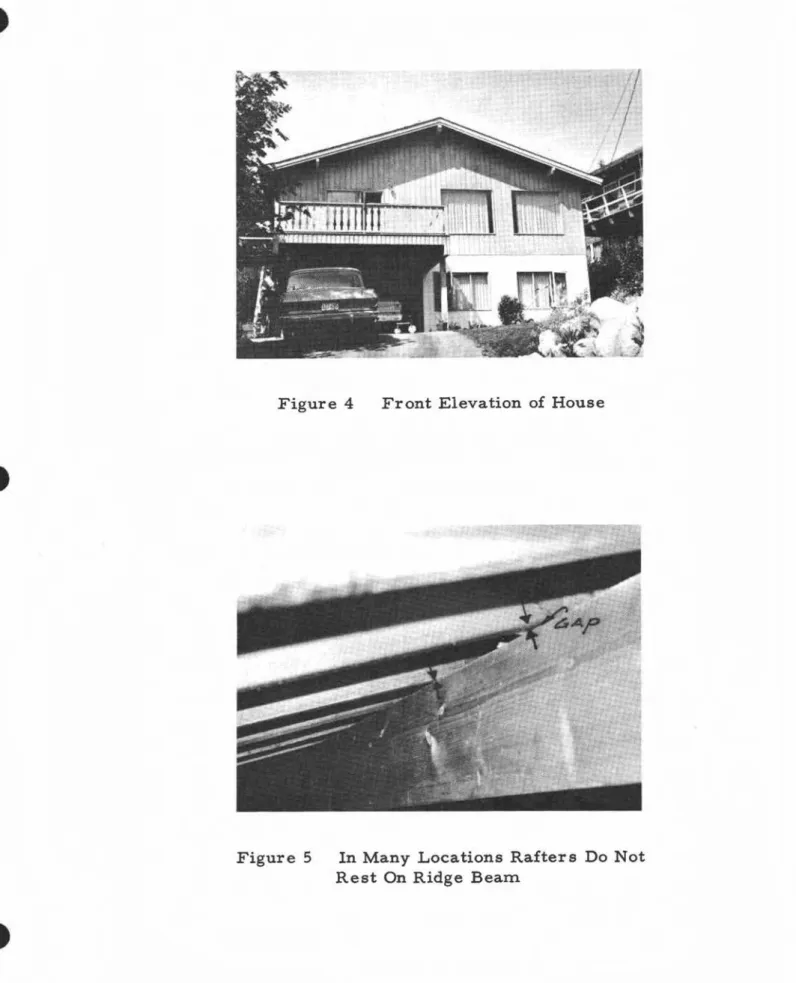
This Note describes plaster cracking in a ceiling of a house. The possible relationship of the cracking to the framing details of the roof and ceiling are discussed. The owner reported that the house was completed in the fall of 1963 and was occupied in early 1964. Figure 4 is a view of the house from the street. Figure 1 is a plan of the second storey of the house with the cracked ceiling. The four lines of cracks are identified in this figure as Crack A-A, Crack B-B, Crack C-C and Crack D-D.
The framing details of the roof and ceiling are shown in Figures 2 and 3. Attention is drawn to the method of end support for the roof rafters that were intended to provide a no-thrust system. In actuality, however, the rafter s are butted tightly at the peak and are tied together with a scab or gusset. It is probable that shrinkage of the ridge beam and in the supporting structure allowed the beam to lose contact with the rafters so that it could not carry roof loads without developing an outward thrust.
The ridge beam had a measured depth of approximately 11 in. on March 22, 1967; many rafters were not bearing on the beam (Figure 5) although in places a measure of bearing is achieved in-directly through the gusset. The detail at the lower end of the roof rafters is normal but the nailing is probably inadequate to resist much outward thrust. The stub joists (2 by 4' s) which are attached
2
-to the roof rafters, and provide support for the ceiling between the wall and the last ceiling joist (2 by 6), would accept thrust from the rafters and could in turn stress the plaster.
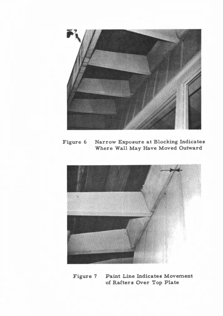
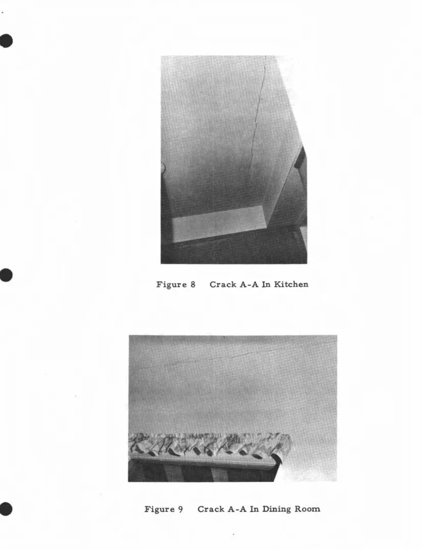
Another possibility is that the thrust in the rafters caused a slight outward movement of the wall (see Figure 6). Again, the stub joists might have followed the wall movement resulting in the plaster being overstressed and cracking. It is thought that Crack A-A shown in Figures 8 and 9 resulted from one or both of the loading conditions described. The owner reported that this crack was in evidence when he first inspected the house. The crack was filled to his satisfaction before the
purchase was made, but it reappeared after the house was occupied. An attempt was made to determine whether the wall was bowed outward but the results were inconclusive. There appear, however, to be clear indications of outward movement of the rafters relative to the wall in the form of narrow unpainted strips on the underside of blocking and rafters (Figure 7). An obvious criticism of the framing arrangement is the lack of adequate bearing area for the rafters on the ridge-beam. The rafters should have been notched to form a flat bearing area on the ridge-beam.
The crack B-B parallels the ct;iling beam shown in Figure 1•.. This beam supports the kitchen and dining room ceiling joists on metal joist hangers (Figure 10). A view of the crack taken from just above floor level is shown in Figure 11. This crack shows
signs of periodic movement. This method of support might encourage periodic movement due to expansion and contraction in the wood.
Seasonal change in moisture content of wood in the attic may vary from 20 per cent in winter to 14 per cent and less in summer.
The crack C-C runs transversely to the line of the ceiling joists (Figure 12). It appears to be a tension crack which is now stable. The cause of this crack is not obvious. There is a possibility of differential drying of the ceiling joists (i. e. drying and thus shrinking above the line of the top surface of the insulation
3
-in advance of the lower portion) caus-ing a general, but temporary, downward deflection of the ceiling. Another possibility is that
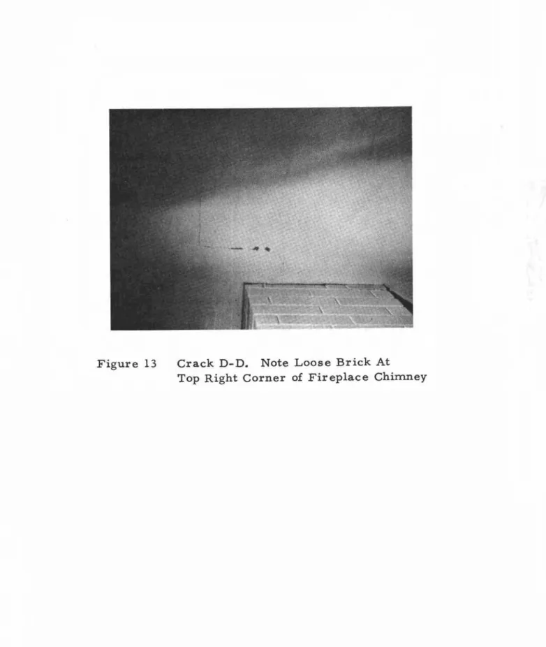
some temporary loading of the ceiling joists might have overstressed the plaster. Crack D-D is associated with the corner of the brick-work of the fireplace (Figure 13) and could have resulted from dif-ferential movement between the wood-framing of the ceiling and the fireplace.
GENERAL COMMENTS
It is unusual to find cracking as extensive as in this case. Of the four cracks identified, the first two are probably of greater interest because of the structural implications involved. It is apparent that for good performance to result, structural systems -even those used in simple house structures - must be based on recog-nized principles, and constructed to accept anticipated loads without excessive displacements or deflections.
REMEDIAL MEASURES
The problem facing the owner is to repair the damage with reasonable assurance that the cracks will not recur. Cracks C-C and D-D should be filled and will probably not re-open. Crack B-B may continue to be a problem unless it is possible to minimize movement of the beam or the beam-joist connections. One approach would be to attempt to stabilize the beam environment by a re-arrange-ment of the vapour barrier and insulation (Figure 14).
The permanent repair of Crack A-A will be very difficult as long as there is a possibility of an outward thrust of the rafter s occurring. This might be remedied by restoring positive bearing between the roof rafters and the ridge-beam using ledger
strips (Figure 15). Care should be taken not to raise the joists, but to just bring them into firm bearing on the ledger. Another approach would be to devise a system of cross-ties to restrain outward move-ment of the lower ends of the roof rafters. This approach would be costly, however, and difficult to install.
.
'"LIVING ROOM
-.J
BEDROOM
--
-0
セ c;-;Jr
=i!:-
. セ-
.-セ
oU'!,--c
U
BATH
I
I -..,;;;l
\
III
II
-
D
,
II..
II\
DINING
II
-
11 I ... ru I Ib--,
KITCHEN
II I II I II I I セa IllA
BII I!
1/!
FIGURE I
KEY TO MAJOR CEILING CRACKS, SECOND FLOOR
,
"L
:::!
(.:Jl'
:-1i10IRECTlON OF
IROOF RAFTERS
" IIROOF RIOGE BEAM)
セ Zセ
===-?
c;-;Jr
I IIxセ
"
"
1
"
-
"!:"-1E
-II IoU
II I ,-II Iセ
I,
I IiiI
CEILING BEAM/
I'e...-.
I!
-rU I'llI;
1'\
"i l:
セ
1.'1 I I ,>
IIi
{
11/
I
I セ\. STUB JOISTS'
xセ
FIGURE 2
APPROXIMATE LAYOUT OF BEAMS, JOISTS AND RAFTERS
OVER PROBLEM AREAS
....
'
FIGURE 3
. ,-"
",
I I I.1---METAL JOIST HANGERS
/ '
2"x6" JOISTS
FIGURE 10
\.:
,.
ADD INSULATION LEVEL
WITH TOP OF JOISTS
POLYETHYLENE
FIGURE 14
PROTECT THE BEAM WITH POLYETHYLENE AND AT LEAST
2" OF INSULATION
INSTALL 2''x
a"
LEDGER STRIPS
WITH TAPERED TOPS.
SHORT LENGTHS
MAY BE REOUIREO
TO ATTAIN UNIFORM
BEARING.
FIGURE 15
SUGGESTED METHOD OF RESTORING RAFTER BEARING TO
RIDGE BEAM
Figure 4 Front Elevation of House
Figure 5 In Many Locations Rafters Do Not Rest On Ridge Beam
Figure 6 Narrow Exposure at Blocking Indicates Where Wall May Have Moved Outward
Figure 7 Paint Line Indicates Movement of Rafters Over Top Plate
Figure 8 Crack A-A In Kitchen
Figure 9 Crack A-A In Dining Room.
Figure 11 View of Crack B-B Taken From. Just Above The Floor
Figure 13 Crack D-D. Note Loose Brick At