CLOSED-LOOP CONTROL
OF ROLL
BENDING/TWISTING:
A SHAPE CONTROL
SYSTEM FOR BEAMS
by
Theresa Clara Jenne
B.S., California State Polytechnic University, Pomona (1984)
SUBMITTED TO THE DEPARTMENT OF
MECHANICAL ENGINEERING IN PARTIAL
FULFILLMENT OF THE REQUIREMENTS FOR THE DEGREE OF
MASTER. OF SCIENCE
at the
LMASSACHUSETTS INSTITUTE OF TECHNOLOGY June 1986
Copyright
©
1986 Massachusetts Institute of TechnologySignature of Author
Depajtr .nt of Mecl .,iical Engineering
June 2, 1986
Certified by
Doctor David E. Hardt Thesis Supervisor
Accepted by
JUL 2 8 1986
Doctor Ain A. Sonin
Chairman, Department Graduate Comittee
Archivs
,, i , . - -- , A
-2-Closed-loop Control of Roll Bending/Twisting: A Shape Control System for Beams
by
Theresa Clara Jenne
Submitted to the Department of Mechanical Engineering on June 2, 1986-in partial fulfillment of the requirements for the degree of Master of Science.
Abstract
Roll bending and roll twisting are processes for forming beams of constant cross section into desired shapes by bending and/or twisting the workpiece while it is rolled through the machine. The objective of the shaping process for beams is to impart a desired angle of twist and a desired curvature at each point along the beam. A closed-loop shape control system was developed by analyzing the mechanics of bending and twisting unsymmetrical beams, such as angles and channels. The shaping process is separated into an unsymmetrical roll bending
operation and a roll twisting operation. The unsymmetrical roll bending operation
bends the workpiece about a specified neutral axis to some desired unloaded
curvature while the workpiece is in the loaded state. The control of the
unsymmetrical roll bending operation is decoupled into two simultaneous, but separate, symmetrical roll bending controllers about each principal axis of inertia. Assuming the workpiece will spring back elastically, each principal axis controller
computes the unloaded curvature from real-time measurements of the loaded curvature, the bending moment, and the bending stiffness of the beam. The roll
twisting operation twists the beam to some desired unloaded angle of twist while the workpiece is rolled through the machine. The closed-loop controller computes the unloaded angle of twist from real-time measurements of the loaded angle of
twist, the twisting torque, and the torsional stiffness of the beam.
Thesis Supervisor: Doctor David E. Hardt
-3-Dedication
-4-Acknowledgements
I would like to thank Professor David Hardt for his support and guidance throughout this research. I would also like to thank the Aluminum Company of America for their financial support and technical assistance. In particular, I would like to thank Professor Hardt and the Aluminum Company of America for allowing me to take time off to be with my family during the recent family tragedy.
In addition, I would like to thank Mike Hale for answering my many questions and his advice concerning this project.
Finally, I thank my family and friends for their love and moral support during
my stay here at MIT. For without them, I would have acked my bags a long time
Table of Contents
Abstract 2 Dedication 3 Acknowledgements 4 Table of Contents 5 List of Figures 9 Notation 11 1. Introduction 15 1.1 MOTIVATION 15 1.1.1 Background 151.1.2 Motivation for Controlling the Unsymmetrical Roll Bending 17 Process
1.1.3 Motivation for Controlling the Roll Twisting Process 20 1.1.4 Motivation for Closed-loop Control of the Shaping Process 21 1.1.4.1 Control of the Symmetrical Roll Bending Process 22
1.1.4.2 Control of the Unsymmeterical Roll Bending Process 24
1.2 OBJECTIVE 24
1.3 THESIS OVERVIEW 2
1.3.1 Controlling the Unsymmetrical Roll Bending Process 25 1.3.2 Controlling the Roll Twisting Process 27 1.3.3 Controlling a Shaping Process for Beams 28
2. Control of the Unsymmetrical Roll Bending Process 30
2.1 INTRODUCTION 30
2.1.1 Assumptions 31
2.2 THE SYMMETRICAL bENDING PROCESS 31
2.2.1 Symmetrical Bending Model 32
2.2.1.1 Plastic Moment-Curvature Relation 33 2.2.1.2 Analysis of the Model Related to Control 34 2.2.2 Control of the Symmetrical Roll Bending Process 36 2.3 THE UNSYMMETRICAL BENDING ROLL BENDING PROCESS 39
2.3.1 Unsymmetrical Bending Model 39
2.3.1.1 Principal Axes of Inertia, Iy 0 43 2.3.1.2 Symmetrical Bending versus Unsymmetrical Bending 44 2.3.2 The Two Degree-of-Freedom Roll Bending Machine 45 2.3.3 Control of the Unsvmmetrical Roll Bending Process 47 2.3.3.1 Desired Neutral Axis and Desired Curvature 47 2.3.3.2 Decoupling the Unsymmetrical Bending Process 49 2.3.4 Motivation for using a Two Degree-of-freedom Roll Bending 51
-6-2.3.5 Plastic Bending of Unsymmetrical Cross Sections 2.4 MEASUREMENT MODEL
2.4.1 Coordinate Transformation From Machine Coordinates to Workpiece Coordinates
2.4.2 Loaded Curvature Measurements 2.4.3 Bending Moment Measurements
2.4.4 On-line Computation of the Principal Axes of Inertia
2.4.5 On-line Computation of the Elastic Moment-Curvature Slope 2.4.6 Set-up Procedure for a Workpiece with an Arbitrary
Cross-section
3. Control of the Roll Twisting Process
3.1 INTRODUCTION
3.2 TORSION MODEL OF WORKPIECE 3.2.1 Assumptions
3.2.2 Elastic Torsion
3.2.3 Torque-Unloaded Angle of Twist Relation 3.3 ROLL TWISTING APPARATUS
3.4 PRIMARY CONTROLLER
3.5 PRELIMINARY CONTROL ANALYSIS
3.5.1 Primary Controller Applied to a Moving Beam 3.5.2 Sequencing of the Beam
3.5.2.1 Limiting the Length, L
3.5.3 Incremental Sequencing of the Beam 3.5.4 Location of Angle Measurement
3.5.4.1 Deviation from the Desired Angle
3.5.4.2 Drift of the Final Angle from the Desired Angle 3.5.4.3 Influence of the Sampling Rate
3.6 ROLL TWISTING PROCESS CONTROLLER
3.6.1 The Inner Loop 3.6.2 The Outer Loop
3.6.3 Position of the Angle Measurements
3.6.4 Computing the commanded angle, com(Zlrel)
3.6.5 Forecasting the agle, (Znrel) 3.6.6 Summary
3.6.7 Inner and Outer Loop Sample Rates 3.6.8 Disturbance Rejection
3.6.9 Potential Problems with the Roll TWisting Process Controller 3.6.9.1 Relative Angle Measurement
3.6.10 Error in measurements due to vibration 3.6.10.1 Torque Measurement Location 3.7 MEASUREMENT MODEL
3.7.1 Angle Measurement
3.7.2 Torque Measurement
3.7.3 Torsional Stiffness Measurement
4. Control of a Shaping Process for Beams
4.1 INTRODUCTION
4.2 DECOUPLING THE BENDING AND TWISTING PROCESSES 4.2.1 The Shear Center
5.1 60 61 64 70 73 74 74 75 75 76 76 76 I' , D, 81 82 88 88 91 93 93 94 94 95 97 97 98 99 99 105 105 108 108 109 109 110 110 112 113 113 115 116 118 118 119 119
4.2.2 Experimental Location of the Shear Center 121 4.2.3 Twisting caused by Off-shear Center Loading During a Bending 123
Process
4.2.3.1 Thick-wall versus Thin-wall Cross Sections 123 4.2.3.2 Twisting Restrained During the Bending Process 125 4.2.4 Twisting Caused by Buckling of Thin-wall Cross Sections 127 4.2.5 Minimizing Off-shear Center Loading with Roll Assembly Design 128 4.3 SHAPE CONTROL SYSTEM FOR BEAMIS OF CONSTANT 133
CROSS-SECTION
4.3.1 The Combined Bending and Twisting Operation 133 4.3.1.1 Thick versus thin-wall cross sections 133 4.3.1.2 Moments of Inertia of the Cross Section 134 4.3.1.3 The feasibility of a combined bending and twisting 135
operation
4.3.2 Control of the Combined Bending and Twisting Process 136 4.3.3 A Shape Control System for Beams Using Separate Bending and 136
Twisting Operations
5. Conclusions and Results 139
5.1 CONTROLLING THE UNSYMMETRICAL ROLL BENDING 139
PROCESS
5.2 CONTROLLING THE ROLL TWISTING PROCESS 141 5.3 CONTROLLING A SHAPING PROCESS FOR BEAMS 144
5.4 FUTURE RESEARCH 146
5.4.1 Proposed Static Experiments 146 5.4.2 Future Research for Bending 147 5.4.3 Future Research for Twisting 148
5.4.4 Other Research 149
References 150
Appendix A. MACHINE
DESIGN
CONCEPTS
FOR
THE 153
UNSYMMETRICAL ROLL BENDING PROCESS
A.1 Conceptual Design for a Two Degree-of-freedom Roll Bending Machine 153 for Straightening
Appendix B. Conceptual Design for a Roll Twisting Machine 156
Appendix C. Proposed Experiments and Experimental Apparatus 158
C.1 Experimental Apparatus 158
C.2 Experiments 159
C.2.1 Unsymmetrical Bending Experiments 159
C.2.1.1 T-section Experiment 163
C.2.1.2 Plastic Bending of Unsymmetrical Beams 163
C.3 Twisting Experiments 164
C.4 Coupling between Bending and Twisting Experiments 164 C.5 Combined Bending and Twisting Process Experiments 165
-8-D.1 COMPUTER PROGRAM FOR SIMULATING ROLL TWISTING 166
List of Figures
Figure 1-1: Setups for Straightening a Channel [2] 16
Figure 1-2: A Three- Roll Bending Arrangement [1] 18
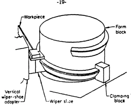
Figure 1-3: Forming an Angle Section into A Ring with Form Block [2] 19
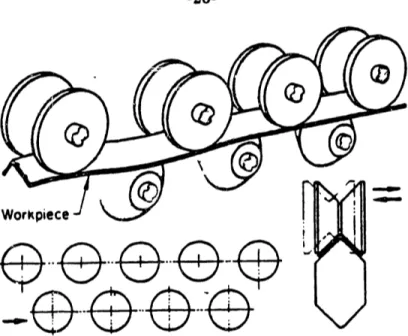
Figure 1-4: Parallel-roll Straightening for an Equal Leg Angle 20
Figure 2-1: Stress-strain Relation (elastic-perfectly plastic material). 32
Figure 2-2: Moment-Curvature Relation of a Rectangular Beam [10] 35
Figure 2-3: Three Roll Bending Arrangement [10]} 37
Figure 2-4: Moment versus Position Relationship [101 37
Figure 2-5: Block Diagram of the Primary Controller [10] 38
Figure 2-6: Bending of an Unsymmetrical Beam 41
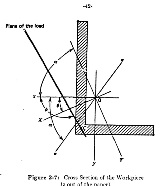
Figure 2-7: Cross Section of the Workpiece (z out of the paper) 42
Figure 2-8: Schematic of the Two Degree-of-freedom Roll Bending 46
Apparatus
Figure 2-9: Control of the Unsymmetrical Roll Bending Operation 48
Figure 2-10: Comparison of 3 Different Methods for Bending an 54 Unsymmetrical Beam
Figure 2-11: Fully Plastic Bending of an Unsymmetrical Beam [3] 56
Figure 2-12: Geometry of an Unequal Leg Angle [3] 59 Figure 2-13: A Two Degree-of-freedom Roll Bending Machine 62
Figure 2-14: Schematic of Center Roll Assembly 64
Figure 2-15: Rotational Transformation of Axes Systems 65
Figure 2-16: Measurement Model for the x-z Plane 68
Figure 2-17: Relation of Transducer Displacement to CurvatUire and 69
Neutral Axis
Figure 3-1: Beam subjected to Torsion 78
Figure 3-2: Torque versus Position Relationship 78
Figure 3-3: Angle of Twist versus Position Relationship 78
Figure 3-4: Torque-Angle of Twist Relation for Unloading a Plastically 80 Deformed Beam,
Figure 3-5: Schernatic of the Roll Twisting Apparatus 83
Figure 3-6: Block Diagram of the Primary Controller 85
Figure 3-7: Primary Controller Step Response 86
Figure 3-8: Shifted Torque-Angle of Twist Relation 87
Figure 3-9: Primary Controller Straightening a Beam. 89
Figure 3-10: Primary Controller applied to Straightening 90
Figure 3-11: Sequencing Process applied to the Beam 92
Figure 3-12: Primary Controller used for Straightening (z = L/4) 96
Figure 3-13: Block Diagram of the Control System or the Roll 100
Twisting Process
Figure 3-14: Computation of the Commanded Angle com(Z Ire) 102
Figure 3-15: Updating Premeasured Angles 104
Figure 3-16: Vibration Model of each Section of the Beam 112
Figure 3-17: Angle Measurement Device 114
Figure 3-18: Fixed Roll Assembly Torque Measurement 117
-10-Figure 4-2: Resolving a Torque and Force at the Centroid into an
equivalent Torque and Force at the Shear Center
Figure 4-3: Cross section subjected to Off-shear Center Loading
Figure 4-4: Rectangular Cross section
Figure 4-5: Unloaded Angle of Twist for a Beam Restrained From
Twisting in a Bending Process
Figure 4-6: Desired Shear Center Loading for an Angle Cross Section
Figure 4-7: Roll Design for an Angle
Figure 4-8: Off-shear Center Loading due to Non-contacting Disks Figure 4-9: Off-shear Center Loading Caused by Roll Misalignment
Figure 4-10: Control System for the Combined Bending and Twisting
-'rocess Figure A-1: Figure B-1: Figure C-1: Figure C-2:
Figure C3:
Design for a two degree-of-freedom Roll Bending Machine Conceptual Design for a Roll Twisting Machine
Experimental Apparatus
Fixed End Assembly
Center Assembly 120 124 126 127 130 130 132 132 137 155 157 160 161 162
Notation
a: distance from outer roll A to center roll A: cross sectional area
b: distance from center roll to outer roll C Cmachtransformation matrix, from machine
P axis system to workpiece axis system
C: shear center
d,D: maximum cross section diameter
e: error
E: modulus of elasticity
f: feed rate of the beam (length/time)
f( ): coordinate transformation matrix transforming (x,y) to (X,Y)
FR: resultant force on workpiece at centroid Fe: the bending force at the shear center
g(O): coordinate transformation natrix transforming (X,Y)
to (x,y)
G: gain
G: shear modulus of elasticity (modulus of rigidity) Ix: moment of inertia with respect to the x-axis Iy: moment of inertia with respect to the y-axis
-12-Ixy: product of inertia with respect to the x and y axes
Ix: principal momhent of inertia with respect to the X-axis
Iy: principal moment of inertia with respect to the Y-axis J: polar moment of inertia
K: curvature
KL: loaded curvature KU: unloaded curvature
L: length of the beam in the machine over which the torque acts.
: the distance between the center roll and the outer rolls (a =b)
M: moment
0: centroid of cross section
r: radius measured from centroid R: radius of curvature
s: Laplace operator t: time
Tc: torque at shear center
TR: resultant torque on workpiece at centroid Tsample the sample time of the controller
TsamplI inner loop sample time TsampOL outer loop sample time
Xc: x coordinate location of shear center xp: deflection of the beam
y¢: y coordinate location of shear center yp deflection of the beam
: position of the y-axis servo
(x,y): rectangular axis system with origin, 0, at centroid of the cross section
(XwpYwpZwp): workpiece axis system (x,y,z): machine axis system
(xOG,yOG,zOG): the axis system attached to
the outer gimbal at the center roll
(X,Y): principal axis system with origin, 0, at centroid of the cross section
Zabs: absolute position on the moving beam relative to end of beam
Zrel position on the beam relative to the machine Znrel position on the workpiece where rel = Znode
Zlrel position relative to the machine where an angle is measured Z2rel position relative to the machine where an angle is measured
a: angle defining neutral axis, CCXV positive
/: angle defining, orientation of the resultant force, FR
A: · change in the angle of twist over the interval, Tsample
. damping ratio
0: angle defining principal axis system
cT: shape factor or torsional constant
~: deflection of beam or center roll displacement a: bending stress
-14-r. shear stress
angle of twist
Ocom commanded angle of twist XL loaded angle of twist
Ou unloaded angle of twist
OUdes(Zabs) the desired unloaded angle of twist
at each position Zabs on the beam 0: angle defining the Diane of loads
V: angle defining rotation of the center roll
wn: natural frequency
Chapter 1
Introduction
1.1 MOTIVATION
A shape control system for beams is needed in the metal industry to form metal stock into a desired hape or to correct dimensional inaccuracies caused by the initial forming process. A shaping process includes straightening an initially deformed bean or forming an initially straight beam. A shape control system for beams bends and twists the beam to a desired shape. Achieving the desired shape requires bending the workpiece about a specified neutral axis for the desired curvature and twisting the workpiece for the desired angle of twist at each point along the beam. In general, the cross section is unsymmetrical (angles, channels, etc. ) in contrast to the simpler case of symmetrical cross sections (squares and
I-beams ).
1.1.1 Background
The most demanding shaping process is straightening an initially deformed beam. One of the simpler methods for straightening a beam is press straightening. The following example illustrates the straightening process for a beam with a channel cross section (Figure 1-1).
The channel is straightened by bending the workpiece in the vertical
plane to remove a constant curvature and then twisting the workpiece to
remove a constant rate of twist. The channel was supported on two blocks 16 inches apart, while force was applied by a pressure ram. A force
-16-of 3000 pounds deflected the part about one inch for a correction -16-of 0.020 inches. Force was applied at two-inch increments along the bar. Two
5-ton hydraulic presses, mounted on a large steel table, were used to remove ihe twist. One ram held one end of the part against a block on the table, while the second ram twisted the part. A slotted bar served as a lever to
twist the channel 30° for a permanent correction of 0.020 inches for each
24 inches, or 0.050 inches for the entire length.
Figure 1-1: Setups for Straightening a Channel [2]
The previous method for straightening the channel is a slow and
time-consuming process. First, the operator must measure the initially deformed channel. Then the operator must design a straightening operation to remove the twist and the curvature from the beam. The straightening operation requires computing the amount of overbend and overtwist to be applied to each particular segment of the channel.
A general straightening process for the channel, or any unsympietrical cross section, would involve an unsymmetrical bending process and a twisting process. The unsymmetrical bending process bends the channel about an specified neutral
unsymmetrical bending process for straightening is to remove a continuously
varying curvature at each point along the beam. The twisting process twists the
channel to remove a continuously varying angle of twist at each point along the
beam. Automating the straightening process is needed to increase production, and
the next logical step for increasing production is to feed the workpiece through rolls
while performing the bending and/or the twisting operation.
1.1.2 Motivation for Controlling the Unsymmetrical Roll Bending Process
A typical rolling arrangement is the one degree-of-freedom roll bending machine. Roll bending is often used to form cylinders from metal plates. A three-roll bending machine configuration is shown in Figure 1-2. The workpiece is subjected to three-point bending while it is rolled through the machine. The
orientation of the neutral axis is determined by the relation between the axes of the
rolls and the workpiece. Once the machine is set up for a part, the neutral axis is fixed and cannot be changed during the process, so the machine only has one degree of freedom and can only bend the workpiece in a fixed plane. The metal plate is fed through the machine by the driven center !!, and the center roll moves in a vertical plane between the fixed outer rolls to provide a variable bending moment. So each point along the length of the beam is ubjected to a maximum moment with a corresponding plastic deformation.
A one degree-of-freedom, (DOF), roll bending machine can bend symmetrical cross sections to a desired shape, but bending an unsymmetrical section with a one DOF machine, such as an angle, does not result in the desired shape, unless special guides are used to compensate for the coupling that occurs in unsymmetrical bending. For example, one method for bending an angle into a ring bends the
-18-Figure 1-2: A Three- Roll Bending Arrangement [1]
workpiece in two planes simultaneously, such that when the shape is removed from the forming machine, it will springback to a ring. In figure 1-3, the angle is bent about a form block into a helical shape. The form block is smaller thin the desired diameter of the ring to bend the workpiece in a circular horizontal plane, and the vertical wiper-shoe bends the workpiece in a vertical plane. When angle section is removed from the machine, the workpiece springs back to the desired shape, a circular ring with a diameter larger than the form block.
An unsymmetrical roll bending process can include straightening an initially deformed beam or forming an initially straight beam by bending the unsymmetrical
beam to a desired curvature about a specified neutral axis. One current method for straightening unsymmetrical beams is parallel-roll straightening. Parallel-roll
straightening is a process for straightening unsymmetrical beams with respect to bending. A parallel-roll straightening process for an angle is shown in figure 1-4.
The vertical distance between the roll centers are adjusted to impose opposite and decreasing bending moments on the workpiece as it passes through the machine.
Figure 1-3: Forming an Angle Section into A Ring with Form Block [21
As the workpiece approaches the machine exit, the bending moments decrease such
that a straight workpiece exits from the machine. The top rolls are adjusted
horizontally to achieve the same effect in the horizontal plane of bending. The workpiece in figure 1-4 is an equal leg channel. The rolls are designed to bend the angle about its principal axes.
Parallel-roll straightening has several disadvantages. One disadvantage is
that the workpiece is bent randomly. so the straightening process is not really
controlled. The straightness of the workpiece is dependent on magnitude of the
bends in the initially deformed beam and the magnitude and quantity of the bends imposed on the beam by the machine. The number of rolls in the machine and how
they are adjusted directly effects the straightness of the workpiece. Another
disadvantage is that special roll design is required to bend certain cross sections
about their principal axes of inertia. The final disadvantage is the cost and
complexity of the machine.
-20-Figure 1-4: Parallel-roll Straightening for an Equal Leg Angle
(The top rolls can be adjusted horizontally and vertically [21.)
unsymmetrical roll bending process and a machine that can bend an unsymmetrical beam about a specified neutral axis to a desired curvature while rolling the beam
through the machine.
1.1.3 Motivation for Controlling the Roll Twisting Process
To date, the roll twisting process has not et been automated. The current
method for straightening a beam, with a random angle of twist along its length,
requires a skilled operator. The operator feeds asection of the beam into a fixture.
The operator then applies a torque over the section of the beam to remove a
constant rate of twist from that section. Each section of the beam is twisted until the entire beam has been straightened. The current method for imparting a
constant rate of twist to a straight beam is by using guides in a rolling process [251,
page 109-110. The guides are adjusted to overtwist the workpiece by the correct amount, such that the workpiece springs back to the desired rate of twist. This
i i .1 1114i
I/ . / -ril-N
--O-requires a skilled operator, who adjusts the guides by a trial and error method [251. Automating the roll twisting process would increase production and increase the
quality of the finished product.
1.1.4 Motivation for Closed-loop Control of the Shaping Process
In the evaluation of different control schemes for a shaping process, it is
important to distinguish between a defined shaping process, which forms an initially straight beam into a desired shape, and a straightening process, which straightens an initially deformed beam. Control schemes which use iterative methods can be applied to a defined shaping process. These types of control schemes rely on extensive material testing to generate data for segments of the desired shape. These types of control schemes are open-loop and cannot reject disturbances, such as random shapes or changes in the material properties of the workpiece, and they cannot be used for a straightening process.
A shaping process includes both straightening and shaping a beam to a desired shape. Controlling the straightening process requires a closed-loop control scheme with good disturbance rejection and command-following properties. In general, a true test of the control scheme is to control the straightening process. Once the straightening process is controlled, the control scheme can be modified for controlling a defined shaping process.
The shape control system for beams was developed by examining several forming processes: the symmetical roll bending process, the unsymmetrical roll bending process, the roll twisting process and the combined roll bending and twisting process. The more advanced control schemes have been developed for the symmetrical roll bending process.
-22-1.1.4.1 Control of the Symmetrical Roll Bending Process
Three-point bending takes place in the symmetrical roll bending process. The
workpiece is bent in a plane about a fixed neutral axis. A skilled operator uses a trial and error method in the static case, as shown in Figure 1-1, or the process is automated by using a one degree-of-freedom roll bending machine, shown in figure 1-2. The force is applied to deflect the workpiece a certain amount, and then the force is removed and the workpiece springs back. The operator measures the unloaded curvature, and then deflects or loads the workpiece again. This process is
continued until the unloaded curvature is correct. The key to controlling the
symmetrical roll bending operation is measuring or predicting the workpiece
springback - the change in the curvature from the loaded state to the unloaded state. The workpiece springback is dependent on the bending stiffness of the
workpiece, the bending moment, and the loaded curvature. The bending stiffness of the workpiece is related to the yield stress and strain hardening characteristics of the material and the geometry of the cross section.
The early control schemes for the bending process consisted of iterative methods to sequentially bend arc segments of the beam [23, 16]. Sachs and Shanley used emperical data for springback compensation [18, 20]. Other researchers used
various analytical methods to predict the residual stress distribution and
springback [8, 19, 6. Hansen and Jannerup developed a model for the roll bending process [11]. Cook, Hansen, and Jannerup used the model in a control scheme for the roll bending process which relied on knowing the material properties in advance
[4]. Many of these approaches require springback curves, which require extensive
material testing to generate. None of the above approaches incorporate material
adaptive control. Foster developed a closed-loop controller which relied on a curvature measurement of the workpiece after it had exited from the roll bending
machine. This controller did not require prior knowledge of material properties,
but it was only applicable to shapes with relatively constant curvature [7].
More recent research by Hardt, Roberts, and Stelson [12] for the roll bending process and Gossard and Stelson [91 for the brake forming process has resulted in a closed-loop controller for each process, which measures material properties during forming. Research by Hardt, Hale, and Roberts [12, 10, 171 have led to the development of a closed-loop roll bending controller, which measures the material
properties of the workpiece on-line and indirectly measures the unloaded curvature.
The unloaded curvature or springback is computed from real-time measurements of the bending moment, the loaded curvature, and the bending stiffness of the beam, while the workpiece is still in the loaded state. The result is a closed-loop unloaded curvature controller with good command following and disturbance rejection properties. The process is insensitive to material property variation, and can formll a continously varying and arbitrary shape in one pass through the machine. Roberts [17] implemented the control scheme in a one degree-of-freedom roll bending machine, and his experiments resulted in errors of less than 3% for bending
the same material to a constant curvature shape. Tests on different materials bent
to a constant curvature shape resulted in a maximum error of 4.2%. Hale [101 conducted more extensive experiments to investigate the dynamic and control characteristics of the process. Hale refined the controller and investigated different
measurement alternatives, command following capability, and disturbance rejection properties of the controller. He found that the vibration of the workpiece contaminated the bending moment measurement, so bandwidth of the roll bending system is limited by the workpiece vibration. Nevertheless, the closed-loop unloaded curvature control scheme by Hardt, Hale, and Roberts is the most promising and the most versatile of the controllers for the symmetrical roll bending
-24-process [12] [101 [17].
1.1.4.2 Control of the Unsymmeterical Roll Bending Process
Mergler developed a control system for bending arc segments of
unsymmetrical beams. The control scheme consisted of an iterative method to
bend each segment sequentially. Each segment requires at least two "tries"
-bending the segment, allowing it to springback, and then measuring the bend to
compute the desired control action. Mergler did address the problems of twisting and out of plane deformation caused by bending unsymmetrical beams. The machine was designed to approximate a pure bending moment over the segment such that twisting caused by shear stresses was negligible. The design also applied
a counter moment to compensate for out of plane bending [16].
1.2 OBJECTIVE
The objective of this research is to develop a control scheme for a shaping process for beams. The shaping process consists of bending the beam about a specified neutral axis to a desired unloaded curvature Goid twisting the beam to a desired angle of twist at each point along the length of the beam. So the mechanics of bending and twisting a beam need to be analyzed to develop models for the unsymmetrical roll bending process and the roll twisting process. The control scheme for the symmetrical roll bending process, developed by Hardt and Hale, is a closed-loop system and measures material properties on-line. The basic idea is to
extend the control scheme of Hardt and Hale to the unsymmetrical roll bending
process and the roll twisting process to achieve a shape control system for beams.
bending process separately. Machine design concepts for each process will be developed, including recommendations for actuator location and obtaining the desired measurments. The final goal is to present a control scheme for the overall shaping process for beams.
This research is being funded by the Aluminum Company of America, and the particular purpose of this research is to develop machine design concepts and
control schemes for straightening extrusions. After the initial extruding process, the extrusions are severely deformed with respect to bending and twisting. The extrusions are then subjected to stretch straightening to remove the severe bends
and twists. The focus of this research is to straighten the extrusions after the
stretch straightening process to meet quality control standards.
1.3 THESIS OVERVIEW
The thesis is divided into three major parts: the control of the unsymmetrical roll bending process (Chapter 2), the control of the roll twisting process (Chapter
3), and the control of a shaping process for beams (Chapter 4). Finally the major points of each process is summarized in Chapter 5. A shaping process for beams consists of two subprocesses, the unsymmetrical roll bending process and the roll twisting process. First, bending and twisting are assumed to be decoupled, and
separate control systems are developed for the bending process and the twisting
process.
1.3.1 Controlling the Unsymmetrical Roll Bending Process
Chapter 2 presents a control system for the unsymmetrical roll bending process. Unsymmetrical bending is bending the workpiece about a neutral axis, not
-26-necessarily coinciding with a principal axis. The goal of the unsymmetrical roll bending process is to bend the workpiece to a desired curvature about a specified
neutral axis at every point along the beam. The model and control system for the
symmetrical roll bending process, developed by Hardt, Hale, and Roberts, is briefly reviewed to establish the basic control aspects of the roll bending process. The mechanics of unsymmetrical bending are analyzed to develop a model, and the analysis reveals that unsymmetrical bending is coupled by its product of inertia, so
the beam is not necessarily loaded perpendicular to the neutral axis. Unsymmetrical bending can be decoupled into symmetrical bending about each principal axis of inertia. The controller decouples the unsymmetrical bending process into two seperate but simultaneous roll bending controllers about each
principal axis. Each principal axis co.troller predicts the unloaded curvature by
computing the springback of the beam from real-time measurements of the loaded
curvature, the bending moment and the bending stiffness of the beam in principal coordinates. Measurements are made in convenient machine coordinates and
transformed by the controller into principal axes coordinates.
Implementing the control system requires a two degree-of-freedom roll bending machine to bend the workpiece about a specified neutral axis to the desired
curvature. A measurement model details alternative methods for measuring the bending moments and curvatures, and on-line methods for locating the principal
axes and computing the bending stiffness for each principal axis are proposed.
The major results and conclusions of Chapter 2 are summarized in Chapter 4. Appendix A presents a machine design concept for the two DOF roll bending machine. Appendix C.2.1 outlines several proposed experiments for testing the
control system and for resolving several uncertainties about the unsymmetrical roll
1.3.2 Controlling the Roll Twisting Process
Chapter 3 addresses the problem of automating the process of continuously twisting a beam to a desired shape or "roll twisting". The workpiece is subjected to pure torsion by applying a torque about the shear center of the workpiece. The goal of the process is to achieve the desired unloaded angle of twist at each point
along the beam. A mathematical model of the twisting process is presented and
analyzed to develop a suitable control system for the process.
The roll twisting process shares many similiarities with the symmetrical roll bending process, but major differences between the two prevent the direct
application of the roll bending controller. The major problem in the roll twisting process is achieving point by point deformation of the workpiece since a constant torque, applied over a section of the workpiece, plastically deforms the entire
section. The primary controller predicts the unloaded angle of twist by computing
the springback of the beam from real-time mew rements of the loaded angle of
twist, the applied torque,and the torsional stiffness of the beam. To achieve point
by point shape control of the beam in a straightening process, the angle measurement is made as close as possible to where the beam exits the machine.
This reduces the effective length under control to much smaller length than the actual machine. Point by point deformation can be approximated by making the
effective length under control very small. Computer simulations were made to investigate the effect of sensor location, feedrates and sampling times. Other possible solutions for the point by point shape control of the beam are presented
and analyzed. Potential problems with the roll twisting process controller are
discussed, and possible solutions are presented.
-28-presented in Chapter 5. Appendix B presents a conceptual design for a roll twisting machine. The continuous nature of the roll twisting process is difficult to model accurately, so Appendix C outlines experiments for testing the control
system for the roll twisting process. A computer program for simulating the roll
twisting process is in AppendixD.
1.3.3 Controlling a Shaping Process for Beams
Chapter 4 discusses controlling a shaping process for beams. An ideal shape control system for beams of constant cross section would simultaneously perform two-plane roll bending for the desired curvature and roll twisting for the desired angle of twist. First, the mechanics of bending and twisting are analyzed to investigate the coupling between bending and twisting. The analysis reveals that thick-wall cross sections are generally insensitive to the coupling between bending and twisting while thin-wall cross sections are sensitive. Two control schemes for the shaping process are proposed. The first control system is for a combined bending and twisting operation for thick-wall cross sections. The combined bending and twisting operation is feasible for thick-wall cross sections, but it is not recommended for thin-wall cross sections. Thin-wall cross sections are sensitive to off-shear center loading, require large angle of twists, and are sensitive to violations of cross sectional property assumptions used in the roll bending controller. The second control systenm divides the bending and twisting operations into two separate processes, the roll bending process and the roll twisting process, for thin-wall cross sections.
Chapter 5 contains the major results of the investigation for controlling a
shaping process for beams. In Appendix C, experiments are proposed to evaluate the feasibility of a combined bending and twisting operation for thin-wall cross
sections. In addition, experiments for on-line location of the shear center and investigating the coupling between bending and twisting are presented.
-30-Chapter 2
Control of the Unsymmetrical
Roll Bending Process
2.1 INTRODUCTION
Understanding and controlling the unsymmetrical roll bending process is
essential to developing a shape control system for beams. In this chapter, bending
and twisting are assumed to be decoupled, so the only focus will be to control
the unsymmetrical roll bending process. The goal of the unsymmetrical roll bending process is to bend the workpiece to a desired curvature about a specified neutral axis at every point along the beam. Since the symmetrical roll bending process has been successfully controlled, the first step is to review the model of the symmetrical roll bending process and the analysis which led to a successful control scheme. Next, the mechanics of unsymmetrical bending will be analyzed to develop a suitable model for the process, and then determine how the basic control concepts of the symmetrical bending process can be applied to the unsymmetrical bending process. The pros and cons of using a one degree-of-freedom (DOF) roll bending machine versus a two DOF roll bending machine for controlling the unsymmetrical bending process are discussed. The two DOF machine is selected to control the unsymmetrical roll bending process, and a closed-loop control system which measures material properties on-line and indirectly measures the unloaded curvature is presented. Finally, a model for measuring the loaded curvatures and bending moments, and on-line methods f Measuring the bending stiffness and the principal axes of inertia are described.
2.1.1 Assumptions
The assumptions used in developing a model for the unsymmetrical bending process include:
- The workpiece is a beam with a constant cross section of arbitrary shape.
- A planar cross section of the beam remains a planar during bending [21]. - The workpiece is not subjected to axial or torsional loads [21].
- The workpiece is made of an elastic-perfectly plastic material with the
stress-strain relation shown in Figure 2-1, and the material is
homogeneous and isotropic.
-The shear stress caused by the tranverse loading is negligible if the length of the beam, L, is large compared to the maximum cross section diameter, d. The shearing stress is assumed negligible in comparison to
the bending stress if the ratio L/d > 5 [3].
- The workpiece is subjected to three-point loading applied at the shear
center of the workpiece. Loading the workpiece at its shear center
allows the beam to be bent with twisting [13J.
2.2 THE SYMMETRICAL BENDING PROCESS
This section is the result of research and ex.perimental verification conducted by Hale, Hardt and Roberts [12, 10, 171 in controlling and modelling the symmetrical roll bending process using a one degree-of-freedom roll bending machine. A symmetrical bending model is developed, and the control scheme for the symmetrical roll bending process is reviewed. The result is a closed-loop
system which measures material properties on-line and indirectly
-32-a
h.
Cn
Strain
Figure 2-1: Stress-strain Relation
(elastic-perfectly plastic material).
unloaded curvature while still in the loaded state, compares the measured unloaded curvature with the desired unloaded curvature, and uses the error signal to command the servo. The reader is encouraged to review Hale'; thesis for a more
in-depth treatment of controlling the symmetrical bending process [101.
2.2.1 Symmetrical Bending Model
Symmetrical bending is defined as bending a workpiece about an axis of
symmetry. Based on the assumption that the shear stresses are negligible, the only non-zero stress component is the longitudinal stress distribution, Ozz. Assuming the
material obeys Hooke's law, the strain can be described by the curvature of the beam, K, and the distance from the neutral axis, x,
o0- -E K (2.1)
where E is the modulus of elasticity and is dependent on the material properties of the workpiece. For the beam to be in equilibrium, the bending stress integrated over the area must equal the bending moment, My.
My - z z dA (2.2)
Substituting equation (2.1) into equation (2.2) results in the moment-curvature relationship for an elastic material in bending.
Melastic -E K where Iv d.fi A (2.3)
and Iy is the moment of inertia dependent with respect to the y-axis.
2.2.1.1 Plastic Moment-Curvature Relation
The following analysis derives the moment-curvature relation for a beam
with a solid rectangular cross section for symmetrical bending. The workpiece
is assumed to be made of an elastic-perfectly plastic material. For the portion of the cross section undergoing elastic deformation, (x < Xyld), the bending stress, Cz,
is proportional to the distance from the neutral axis, x,
X
if X<x
if z < yd, Oelastic=--- c2
O'yld - (2.4) XyldFor the portion of the cross section undergoing plastic deformation, the bending
stress is constant.
if > yld, c'plastic =- Oyld (2.5)
Equations, (2.4) and (2.5), are substituted into equation (2.2) and integrated. It can be shown that the curvature is proportional to the distance from the neutral axis,
-34-and the result is
If K Kyid, Melastic = EIy K (2.6)
3 Ml
Kyl
2If K> Kyld, Mplastic -- = y 1.0 2 (2.7)
2 (1.o3 K)
The relationship between the bending moment and the curvature, for
three-point bending, is shown in Figure 2-2. If the loaded curvature, KL, is less than the yield curvature, Kyld, plastic deformation wvill not occur, and the beam will springback to the original curvature, Kinitia. Plastic deformation occurs when K is
loaded past Kyld. Assuming the material unloads elastically, the unloading will parallel the original moment-curvature curve in the elastic region (slope of 1/(E I))
and the springback at the center roll can be computed from
M y
KU = KL- 1 (2.8)
EIy
where Ku is the unloaded curvature and KL is the loaded curvature at the center
roll.
2.2.1.2 Analysis of the Model Related to Control
The moment-curvature relationship of Figure 2-2 is dependent on the shape of the cross section and the material properties of the beam. Material properties such
as the yield stress and strain hardening can vary for different materials. Computing the plastic deformation of an arbitrary cross section requires a limit analysis, similiar to the analysis in section 2.2.1.1, based on the shape of the cress
section and the material properties. D. Hardt and M. Hale eliminated the problems of predicting the plastic deformation with limit analysis by simply measuring the applied moment and the loaded curvature, while the workpiece is in the loaded
Mm
C
Figure 2-2: Moment-Curvature Relation of a Rectangular Beam [10]
state 12] [10].
If the applied moment, M, and the loaded curvature, KL, are measured, then the
predicted springback can be computed from equation (2.8). In addition, the bending
stiffness, (E I), is measured by elastically loading a straight beam and measuring the
moment, M, and the loaded curvature, KL. The bending stiffness, (E I), is then
computed from equation (2.3). Now the unloaded curvature relies only on the
assumption that the beam will springback elastically; all other properties are directly measured from the workpiece.
-36-only on the assumption that the beam will springback elastically; all other properties are directly measured from the workpiece.
The maximum loaded curvature, KL, takes place at the location of the
maximum moment which is at the center roll shown in Figures, 2-3 and 2-4. A fixed point on the workpiece moving through the roll bending apparatus is assumed
to experience plastic deformation only at the location of the maximum moment. As the fixed point on the workpiece moves through the bending apparatus, the point
experiences an increasing bending moment until it passes through the center roll.
At the center roll, the point is plastically deformed. When the point moves past
the center roll, the bending moment decreases and no longer plastically deforms the
point. This allows the assumption of point by point deformation of the
workpiece as it passes under the center roll.
2.2.2 Control of the Symmetrical Roll Bending Process
The control of the symmetrical roll bending operation is based on the primary
controller of Figure 2-5. Real time measurements of the loaded curvature, KL, and
the applied bending moment, M, indirectly measures the unloaded curvature, KU (equation (2.8)). The feedback controller generates an error signal by comparing
the indirectly measured unloaded curvature, KU, to the desired unloaded curvature, Kudes The error signal then commands the servo to deflect the workpiece in the manner required to null the error signal. Thus, the primary controller shown in Figure 2-5, causes the workpiece unloaded curvature, KU, to track the desired
unloaded curvature, KUdes
M. Hale designed the primary controller for the symmetrical roll bending
_ - -_ _ _-
-- _ _ _
_-d2
Figure 2-3: Three Roll Bending Arrangement [10]}
Workpiece
Movement
Moment versus Position Relationship [10]
E 0
a
C B ro I11 nll inch RollerFigure 24:
-38-Figure 2-5: Block Diagram of the Primary Controller [10]
transfer function of the servo is assumed to be first order. A proportional
controller with velocity feedback resulted in a second order closed loop transfer function:
Ku G
- - (2.9)
K{des KUdes s" + 2 w + n n+w-22
where the damping ration, , was designed with sufficient damping to avoid overshoot. The vibration of free ends of the workpiece contaminates the
bending moment measurement, so the ibration severely limits the
bandwidth of the system. [101
2.3 THE UNSYMMETRICAL BENDING ROLL BENDING PROCESS
Bending a beam about an axis of symmetry implies that the product of inertia
is zero, and bending will only occur in a plane orthogonal to the axis of symmetry. Bending a beam about an axis that is not an axis of symmetry is known as
unsymmetrical bending. Unsymmetrical bending implies that the product of inertia
is non-zero and coupling will exist. If an unsymmetrical beam is loaded perpendicular to the desired neutral axis, as in symmetrical bending, the workpiece can bend about some other neutral axis. The following sections analyzes the mechanics of unsymmetrical bending to develop a model for the unsymmetrical roll bending process. Then a control system is developed for the unsymmetrical roll bonding process. The objective is to bend the workpiece to a desired curvature
about a specified neutral axis at every point along the beam.
2.3.1 Unsymmetrical Bending Model
The beam has a constant cross section of some arbitrary shape. In general, the cross section of the workpiece does not have an axis of symmetry, so the workpiece is unsymmetrical. The angle shown in Figure 2-7 is an unequal leg angle without an axis of symmetry. The beam is bent about a specified neutral axis to a
desired curvature. The angle, , and the centroid, 0, define the neutral axis of the beam, designated by the line n-n. The curvature, K, is perpendicular to the neutral axis. The curvature is positive if it produces compressive stresses on the positive
axis, so the center of curvature will lie on the positive side of the axis. The machine coordinate system (x,y) is defined as having its origin, 0, at the centroid of the cross sectional area as shown in Figures 2-6 and 2-7. In Figure 2-6, this implies that a positive bending moment, My, produces a positive curvature, Kx. Similiarly,
-40-a positive Mx produces a negative curvature, Ky.
For bending and twisting to be decoupled, the line of action ofi the resultant
bending forces must pass through the shear center of the workpiece. (The shear
center will be discussed in more detail in Chapter 4.) The axial line which passes
through the shear centers of all the cross sections on the beam is the bending axis
in Figure 2-6. The plane in which'the bending moment, M, is applied is called the
plane of loads. The plane of loads is defined by the angle, , and the shear
center, C, and is measured with respect to the x-axis and is positive in the CCW
sense. For bending without twisting, the plane of loads, at each point along the
beam, must contain the bending axis or pass through the shear center of each cross
section. For bending without twisting, the centroidal axis will then parallel the
bending axis.
Assuming transverse shear stresses are negligible, the only non-zero stress
component is the longitudinal stress distribution, azz. Assuming the material obeys
Hooke's law, the strain can be described by the curvature of the beam, K(x,y), and
the distance from the neutral axis, (,y).
Crzz= - E ( Kx + y Ky) (2.10)
For the beam to be in equilibrium, the shear stress integrated over the cross
sectional area must equal the bending moment, Nlzty).
Mx -=
uzzdA
= -
E (Ixy K
x+
I
Ky)
(2.11)
My =-- frozz dA = E (Iy Kx + IXY Ky) (2.12)
where Ix is the moment of inertia with respect to the x-axis,
Plow of load
x
Figure 2-8: Bending of an Unsymmetrical Beam
and Iy is the moment of inertia with respect to the y-axis,
I=fzdA
(2.14)and Ixy is the product of inertia with respect to both axes.
~~~~I = X~~~~~~~~~y- ~(2.15) dA
-42-Plane of x X Y m
Figure 2-7: Cross Section of the Workpiece
(z out of the paper)
Substituting equation (2.10) in equations (2.11) and (2.12) and solving for azz results
in the flexure stress distribution normal to the cross section. The bending stress,
Czz, in (,y) coordinates is given by equation (2.16) [3J.
(My Ix + Mx IxV) (NIX Iy + My IXy)
a=-z (MI- MI)ly (MI+MI)(2.16)
uzz- (lI x II I xy ) y - ( ()x xy I2
Rewriting equations (2.11) and (2.12) results in equations, (2.17) and (2.18). One
can see that along the x-axis (y - 0), the curvature, IKc is still dependent on both
the bending moments, Mx and My due to the product of inertia. Ixy
(M I + MIx (xv)
K
.
,
=
(2.17)
Likewise, along the y-axis, (z = 0),
-(MI+MIxy
KY
-(
I IX) (2.18)Ky (Ix ly - xy2) E
In unsymmetrical bending, the bending moments, Mx and My, and the curvatures,
Kx and Ky, are coupled. Applying a bending moment about the x-axis will produce
curvatures, Kx and Ky. On the other hand, bending the workpiece about a neutral axis, coinciding with the x-axis (Ky = 0) will require bending moments, M and My. In general, the plane of loads is not orthogonal to the neutral axis for unsymmetrical bending. However, for a symmetrical workpiece, Iy is zero, and equations (2.17) and (2.18) are uncoupled.
2.3.1.1 Principal Axes of Inertia, Ixy =0
Unsymmetrical bending can be decoupled into symmetrical bending about each principal axis of inertia. The principal axes of inertia are defined as the coordinate system, (X,Y), for which the product of inertia, Ixy is zero. Let the origin of both coordinate systems coincide, and let be the angle that the
coordinate system, (x,y), must be rotated to coincide with the coordinate system,
(X,Y), and be defined positive in the counter clockwise sense. The relationship for 0 can be found from equation (2.19) [3].
-21
tan(20) = - (2.19)
I-y
Assuming Ix is greater than I, the principal moments of inertia can be found from
2~~~~~~)
I
X
-- (I.0)
I= 4
I[(4
x
- Iy)/2]2 + (Ixy)2 (2.20)Iy x Y
[(I - I )/2]
2+ (Ixy)
2(2.21)
-44-The relationship between the two coordinate systems is shown in Figure 2-7. Based
on the coordinate systems in Figure 2-7, the coordinate transformation from the
original coordinates, (x,y), to the principal coordinates, (X,Y), are found from
[x [cos(O) sin(O)l [x
[Y] E-sin(@)
cos(O)J [yJ (2.22)and similiarly,
[x] =
r
cos(6) -sin(6)l [X1LYJ
[
sin(O) cos(O)J [YJ (2.23)2.3.1.2 Symmetrical Bending versus Unsymmetrical Bending
In symmetrical bending the product of inertia is zero, and the following
analysis illustrates that the moment-curvature relations of equations (2.17) and
(2.18) for a workpiece subjected to unsymmetrical bending can be decoupled about each of its principal axis to yield a linear relationship between the moment and
curvature.
Since the principal axes of inertia require Ixy = 0, equation (2.16) simplifies to
My Mx
af =-X---+ Y-
(2.24)
IY Ix
in principal axis coordinates. Along the X principal axis, (Y = 0), the principal axis curvature, Kx, equation (2.17) reduces to
My
KX = (2.25)
E Iy
and is only dependent on deflection in the X-z plane. Along the Y principal axis,
-Mx
K =- (2.26)
Y ElX
and is only dependent on deflection in the Y-z plane.
The workpiece is subjected to symmetrical bending if the neutral axis
coincides with one of the principal axes, or n r
a = + - where n is an integer (2.27)
2
For all other values of a, the workpiece is subjected to unsymmetrical bending.
Loading the workpiece orthogonal to the neutral axis will bend the workpiece about
the neutral axis for symmetrical bending. In unsymmetrical bending, loading the
workpiece orthogonal to the neutral axis will not result in the workpiece bending about the same neutral axis.
2.3.2 The Two Degree-of-Freedom Roll Bending Machine
Assume the workpiece is subjected to three-point loading, as shown in Figure 2-8, and the rolls are designed to minimize twisting such that the line of action of the loads is applied through the shear center, C, of the workpiece. For convenience, assume that the machine coordinate system, in Figure 2-8 coincides with the centroid of the cross section. The rolls at the origin (z = 0) and at the end (z = 2L) of the workpiece are fixed, and thetwo servos at the center (z = L)
of the machine position the center rolls to deflect the workpiece along the x-axis,
xp, and the y-axis, yp. The deflected beam bends about a neutral axis (defined by the angle, a, relative to the x-axis where the bending stress, azz is zero).
-46-L
I
-x
p L
Figure 2-8: Schematic of the Two Degree-of-freedom Roll Bending Apparatus
The rolls at z = 0 and z = L are fixed. The x-axis and y-axis servo deflect the workpiece.
sembly -acez
as'
tie
th
vo1 __ -1 ,&A -A.I
2.3.3 Control of the Unsymmetrical Roll Bending Process
The control of the roll bending operation can be decoupled into two simultaneous but separate symmetrical roll bending control systems for each
principal axis. The proposed control system is shown in Figure 2-9 and utilizes the symmetrical roll bending control system, section 2.2. The curvatures, Kx and Ky,
and the bending moments, Mx and My are measured in machine coordinates, (x,y),
as defined in Figure 2-7. The bending moments are measured with respect to the shear center. The measurements are then transformed into principal axis coordinates, (X,Y), to allow the unsymmetrical roll bending to be decoupled. The
error signals, eX and ey, for each principal axis, X and Y, are domputed and transformed into (x,y) coordinates, ex and ey, and sent to the controller for each servo.
2.3.3.1 Desired Neutral Axis and Desired Curvature
The desired outcome of the roll bending operation is to bend the workpiece about a specified neutral axis to some desired curvature, The neutral axis (n-n in Figure 2-7) is defined as an axis on the cross section of the beam where the stress,
azz is zero, and establishes how the workpiece is to be bent. Let the angle, a, relative to the x-axis, define the neutral axis, n-n, passing through the centroid of the cross section. The desired curvature, K es, at the maximum moment is defined as
KUdes = 1 / R (2.28)
where R is the radius of curvature (shown in Figure 2-8) orthogonal to the neutral axis. Employing small angle approximations, it can be shown that the curvatures in the x-z plane and the y-z plane are simply the components of the curvature, K
wC w Q 0.- 0 x C.) E' Ca coU) c. I n o ~ ,.. ,-
'1
o i Y -z a C ' e -* ._ - P ,- , ~~U-~E'^ -
c
g 0rs= · C ,,4) ,~.C ~ a:-48-[5]. From the geometry of Figure 2-8, the desired unloaded curvature in the (x,y)
coordinates can be computed.
KUxdes KUdes sin(a) (2.29)
KUydes = KUdes cos(a) (2.30)
where the curvature is defined positive, if the center of curvature lies on the positive axis.
2.3.3.2 Decoupling the Unsymmetrical Bending Process
In principal coordinates, the unsymmetrical roll bending control system is
uncoupled into two independent control systems along each principal axis (equations (2.25) and (2.26)). If the rolls of the roll bending machine were designed to align the X and Y principal axes of the workpiece with the x-axis servo and the y-axis servo of the machine, then the X-axis servo will only affect the X-axis curvature, Kx, and the Y-axis servo will only affect the Y-axis curvature, Ky. However, such a roll design would be costly, so the controller performs a coordinate transformation to control in the principal axis coordinates.
The measurements from the workpiece - the loaded curvatures, KLX, KLy, and
the bending moments, M and My in machine coordinates- are transformed into principal axes coordinates by equations (2.31) and (2.32).
KLx1 = [ cos(O) sin(O)1 [KLx1
KLYJ -sin(O) cos(O)j [KLyJ (2.31)
[MX = [ cos(O) sin(O) MX
MYJ -sin(O) cos(O)J [MyJ (2.32)
-50-equations (2.33) and (2.34), based on the symmetrical roll bending model.
My
KUX = KLX EI (2.33)
Mx
-- = LY (2.34)
E Ix
Assume the angle, a, defining the neutral axis and the desired curvature,
KUdes, have been specified. The desired curvature computed in equations (2.29)
and (2.30) are transformed into principal coordinates by equations (2.35).
[KUXdes
=[
cos(6) sin(6)l [KIXdes]KuYdes L-sin(O) cos(9)J KUydes (2.35)
The error signals are then computed in principal coordinates,
eX -= KXdes - Kt
x(2.36)
ey = KUYdes - KuY (2.37)
It can be shown that the unloaded curvature is proportional to the deflection of the beam, or the center roll displacement, and is dependent on the the geometry of the roll bending apparatus [101.
IfX < Xpyld then Kux = 0.0 3 Xp
If Xp Xpyld then KX P (2.38)
where a and b are the distances between the center roll and each outer roll,
respectively. In principal coordinates, the center roll displacement, X,, Y, is p' p' proportional to the unloaded curvature.
a b KX
XP (2.39)
![Figure 1-1: Setups for Straightening a Channel [2]](https://thumb-eu.123doks.com/thumbv2/123doknet/14338617.498935/16.918.219.777.378.619/figure-setups-for-straightening-a-channel.webp)
![Figure 1-2: A Three- Roll Bending Arrangement [1]](https://thumb-eu.123doks.com/thumbv2/123doknet/14338617.498935/18.918.334.691.98.469/figure-roll-bending-arrangement.webp)

![Figure 2-2: Moment-Curvature Relation of a Rectangular Beam [10]](https://thumb-eu.123doks.com/thumbv2/123doknet/14338617.498935/35.918.162.755.188.655/figure-moment-curvature-relation-rectangular-beam.webp)
![Figure 2-3: Three Roll Bending Arrangement [10]}](https://thumb-eu.123doks.com/thumbv2/123doknet/14338617.498935/37.918.183.752.106.560/figure-roll-bending-arrangement.webp)
![Figure 2-5: Block Diagram of the Primary Controller [10]](https://thumb-eu.123doks.com/thumbv2/123doknet/14338617.498935/38.918.164.827.185.487/figure-block-diagram-primary-controller.webp)