HAL Id: hal-03079710
https://hal.archives-ouvertes.fr/hal-03079710
Submitted on 5 Jan 2021HAL is a multi-disciplinary open access archive for the deposit and dissemination of sci-entific research documents, whether they are pub-lished or not. The documents may come from teaching and research institutions in France or abroad, or from public or private research centers.
L’archive ouverte pluridisciplinaire HAL, est destinée au dépôt et à la diffusion de documents scientifiques de niveau recherche, publiés ou non, émanant des établissements d’enseignement et de recherche français ou étrangers, des laboratoires publics ou privés.
STRAIGHTFORWARD EMDRIVE SETUP USING A
MICROWAVE CONTACTLESS TRANSITION: FIRST
RESULTS ON FRUSTUM CAVITIES
Hugo Peyre, Jérôme Sokoloff, Olivier Pascal, Olivier Pigaglio, Nathalie Raveu
To cite this version:
Hugo Peyre, Jérôme Sokoloff, Olivier Pascal, Olivier Pigaglio, Nathalie Raveu. STRAIGHTFOR-WARD EMDRIVE SETUP USING A MICROWAVE CONTACTLESS TRANSITION: FIRST RE-SULTS ON FRUSTUM CAVITIES. Progress In Electromagnetics Research M, EMW Publishing, 2020, 95, pp.45-52. �10.2528/PIERM20052905�. �hal-03079710�
Straightforward EMDrive Setup Using a Microwave Contactless
Transition: First Results on Frustum Cavities
Hugo Peyre*, J´erˆome Sokoloff, Olivier Pascal, Olivier Pigaglio, and Nathalie Raveu
Abstract—This paper presents the work of the LAPLACE Electromagnetism Research Group to build an experimental setup able to measure tiny forces that may appear in microwave cavities, in the context of EMDrive investigations. It is based on a commercial balance in the range of 0.1 mN sensitivity, a contactless feeding for more than 150 W RF power, and self calibrating device process. It requires a double cavity system in mirror configuration and is here experimented with frustum cavities, different from the NASA one [1]. The global setup can make force measurement and calibration in less than two seconds. Investigating two different cavities and various electromagnetic modes for the biggest, no force is reported while the 0.1 mN sensitivity is demonstrated.
1. INTRODUCTION
The EMDrive concept is based on the idea that an asymmetric resonant cavity fed by microwave power would produce a non-zero resulting force, hence violating the momentum conservation: Newton’s third law. Although extremely weak, the existence of such a force may have huge consequences either in fundamental physics or spatial propulsion. This is the reason that EMDrive research and EMDrive-like force measurement are currently big challenges.
While McCulloch gives a possible theoretical explanation for the phenomenon [2], any EMDrive-like force demonstration seems to be achievable only through experimental work. In 2016, White et al., from NASA, experimentally demonstrated the production of an EMDrive-like force by a frustum cavity. This work constitutes the first peer-reviewed EMDrive paper [1] claiming an efficiency of 1.2 mN/kW for their cavity. A couple of years later, a German research team (TU Dresden), led by Tajmar, replicated the NASA’s experiment implementing others cavity configuration at different frequencies [3]. However, they could not conclude on the existence of an EMDrive-like force because of the presence of parasitic forces (thermal, electromagnetic, etc.). Although these two setups are very sensitive, the significant mass hanged on a torsion pendulum causes inertia. It requires to wait for tens of seconds to record data that have to be carefully post-processed to extract forces. The difficulty for calibrating, using reference configurations or forces without modifying the measure environment, appears to be a key in the challenge of having conclusive results.
The objective of this paper is to present the improved LAPLACE’s EMDrive experimental setup and its first qualification tests with frustum cavities different from the NASA one [1]. This setup aims to provide a straight and fast response, capable of testing a wide diversity of cavities or resonant modes. It constitutes our contribution to the scientific community so that a larger number of research teams can take part in the EMDrive scientific debate.
This article is the third in our publishing approach detailing the advances of the setup. The first one focused on the development of this handy and affordable experimental setup [4]. It also revealed results obtained with a set of cavities in “Shaker” original self-calibrating configuration. This mirror
Received 29 May 2020, Accepted 14 July 2020, Scheduled 7 August 2020 * Corresponding author: Hugo Peyre ([email protected]).
46 Peyre et al.
configuration made it possible to discriminate the hypothetical force against the parasitic forces. The conclusions were that no EMDrive-like force could be demonstrated above our sensitivity of 0.5 mN, and that the thermal effect of the coaxial cable (feeding the cavities) was the main parasitic effect.
To eliminate this parasitic effect, a contactless microwave transition has next been designed. Its characterization is presented in the second publication [5]. It was found to exhibit satisfying electromagnetic performances and to transmit 150 W microwave power without affecting the force measurement.
This third paper is now presenting the EMDrive-like force measurements performed thanks to the assembly of the Shaker configuration together with the contactless microwave transition. The elimination of the thermal parasitic effect of the cable makes it possible to imagine and implement a straighter and faster experimental protocol which will radically improve the sensitivity of the setup (Section 3.3). Moreover, in order to explore a wider diversity of resonant modes with higher quality factor, another set of cavities has been realized (Section 2.2). In this study, a total of three modes will be exploited in an attempt to produce forces, whose measurements are reported in Section 4.
2. EQUIPMENT
2.1. Experimental Setup
The description of the EMDrive experimental setup developed at the Plasma and Energy Conversion Lab (LAPLACE, Toulouse, France) is detailed in [4]. A solid-state generator provides CW microwave power up to 200 W. It can be accurately tuned from 2.43 to 2.47 GHz in order to properly feed a narrow bandwidth resonant cavity. In addition, force measurement is performed with a precision balance having a display accuracy of 10 mg (≈ 0.1 mN). The whole setup is placed on a marble block to lower environmental noise on the balance measurement (Figure 1) [4].
The RF power unit feeds resonant cavities in a Shaker configuration (Figure 1). This original
j b c e i f d g h k a
Figure 1. LAPLACE’s EMDrive experimental setup mounted (a) on a marble block. (b) Under the Plexiglas enclosure, the operating part includes (c) the resonant cavities in Shaker configuration (here: Big Shaker) placed (d) on the precision balance and (e) fed thanks to a contactless microwave transition; (f) power probes collect the incident and reflected powers, and (g) standard weights are used for the calibration processes of the balance. On the left of the enclosure, the monitoring part is made of (h) the microwave source, (i) the powermeters, a computer for (j) real-time control and (k) the switch command to select which cavity to feed.
configuration, proposed in [4], is an assembly of two identical cavities oriented in opposite directions. A microwave switch selects which cavity is fed. If an EMDrive-like force exists, it then becomes possible to almost instantaneously generate a thrust alternately directed downwards or upwards, without changing any parasitic effect.
This configuration first aims at discriminating the parasitic effects by making a simple instant difference between the two measured forces, and it secondly aims at measuring a relative force of twice the EMDrive-like force at the instant of the cavity switch: it therefore doubles the setup sensitivity.
The main objective of this paper is to present the first EMDrive-like force measurements performed thanks to the assembly of the Shaker configuration with our contactless microwave transition (Figure 1). This transition has been designed to transmit high microwave power (≈ 150 W) using two separate channels without affecting the force measurement [5]. Although a low gap difference has a minimal influence on the electromagnetic performances of the contactless transition, an effort has been made to maintain an air gap of 3 mm between the two parts of the transition, throughout the whole study.
2.2. Resonant Cavities
After the work described in [4] and [5] and for this third step of the EMDrive setup development at the LAPLACE, we are using a simple design of frustum cavity (without any dielectric part) that has been previously simulated and manufactured in two units. These cavities’ shape creates an electromagnetic asymmetry (conical angle of 58◦) seemingly necessary to produce an EMDrive-like force. Their dimensions have been set so that the fundamental mode can be excited in the frequency band of the generator. Indeed, it is the simplest mode to drive and leads to the smallest dimensions and therefore to the minimal weight. The inner diameter is 40 mm at the small end and 119.8 mm at the large end. The axial height is 63.85 mm. Further in this paper, these two cavities and the Shaker configuration that they form will be called “Cavity 1A”, “Cavity 1B”, and “Small Shaker”.
In our first paper [4], no EMDrive-like force has been experienced above the setup minimum sensitivity. Enhancing the electromagnetic energy stored in the cavity is one possible way to increase this EMDrive-like force. At its resonant frequency, the stored energy ES is directly related to the injected power Pinj and quality factor Q:
ES= Q
2πf0
Pinj (1)
The injected power Pinj is almost already maximized at about 150 W. It is equal to the power delivered by the microwave generator (200 W), from which the losses in the microwave circuit (≈ 50 W,
−1.2 dB) and the reflected power are subtracted. The latter (the reflected power) can often be neglected
at the resonance frequency since the cavity appears quite well matched then. At the end, the quality factor Q therefore needs to be improved to increase the stored energy ES.
In order to explore a greater diversity of electromagnetic configurations with higher quality factor, our strategy has been to increase the cavities’ dimensions homothetically. As a result, we keep the same cavity global shape, and it is only bigger. In this way, the higher order modes found in the frequency band will exhibit higher quality factors and more complex fields distributions. After numerically studying them, this approach leads to the realization of two bigger identical cavities, called “Cavity 2A” and “Cavity 2B”. Their inner diameters are 8.56 cm at the small end and 25.52 cm at the large end, and the heights are 13.57 cm. The Shaker configuration they form is called “Big Shaker”.
With these bigger cavities, several modes can be excited in the 2.43–2.47 GHz bandwidth. Only two of them will be studied because of the chosen excitation probe. Due to the complexity of these two modes, we cannot name them easily, so we will simply label them as modes “α” and “β”.
Table 1 gathers the main information about the cavities and the corresponding excited modes that will be used for EMDrive-like force measurements. All of the electromagnetic performances have been inferred from measurement with a Vector Network Analyzer (VNA).
For the big cavities, the asymmetry of the chosen excitation probe causes the cavities to have to be fed slightly differently in order to be assembled in Shaker configuration. This results in variations in resonance frequencies and matching levels, as shown in Table 1. It can also be checked that the quality factors of the modes fed in these big cavities are greater than that of the fundamental mode. Those
48 Peyre et al.
Table 1. Excited mode characteristics based on VNA measurements (cavities only).
Configurations Small Shaker Big Shaker
Volume of one cavity (cm3) 346.8 3350.1
Modes Fundamental mode Mode α Mode β
Field E (simulations)
Prototypes Cav. 1A Cav. 1B Cav. 2A Cav. 2B Cav. 2A Cav. 2B
Resonant frequency f (MHz) 2440.8 2440.8 2442.7 2442.6 2455.3 2454.5
Matching (dB) −24 −21 −24 −15 −47 −38
Quality factor Q 3,550 3,550 17,020 18,500 6,180 5,070
r →
of mode α are still the highest with 17,020 and 18,500. Nevertheless, mode β is the best matched one (−47 dB and −38 dB).
3. METHODS
3.1. Measuring Setup Performances
Before each measurement run presented in Section 4, a video-recorded calibration routine is carried out to check the sensitivity and the response time of the balance. As in reference [4], F1 class standard weights are put on top of the Shaker configuration, placed on the balance. According to the balance manufacturer’s given sensitivity, we first tested the 10 mg weight and found that it was almost never seen. For this reason, the weight of 20 mg is preferred: it is always detected and is consistently measured as 10 mg (i.e., a 10 mg error), as shown in Figure 2.
Compared to reference [4], the sampling period of the balance has been reduced from 80 to 20 ms. Figure 2 also shows the unpredictable response time of the balance. In the worst case, this time reaches 1 second and will be further considered as the setup minimum time necessary to detect a force of that magnitude (≈ 0.2 mN). -10 0 10 20 -0.5 0 0.5 1 1.5 W eighing (mg) Acquisition time (s) Weighing 1 Weighing 2 Weighing 3 Weighing 4 Weighing 5 Weighing 6
Figure 2. Calibration of the balance with the Big Shaker (Figure 1), mode α. 6 measurements of a 20 mg weight video synchronized to the instant of contact (orange cross).
3.2. Thermal Effects
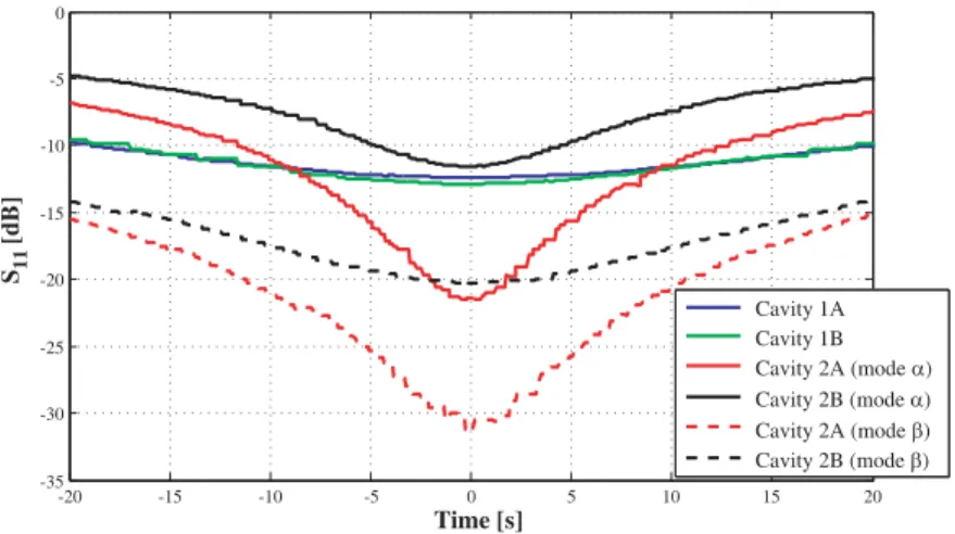
During power-up, the presence of inner surface currents on the walls of the cavity generates ohmic losses. The cavity then heats up, and the longer the power-up is, the hotter it gets. Convection is then created in and around the cavity, and can be a source of parasitic force measurement [1, 6]. Fortunately, none of these thermal induced parasitic forces was high enough to be detected by the balance, even after a 10-minutes long test power-up. No vacuum conditions is then required to avoid convection in our setup. Another consequence of the rise in temperature of the cavity is its mechanical deformation. Due to heating, the cavity increases in volume, and the resonance shifts towards the lower frequencies. At an operating frequency chosen below the resonance, the cavity is sequentially unmatched, matched, and unmatched again as its dimensions increase with time. With 150 W incident power and synchronizing times at resonance, reflection results are shown on Figure 3.
-20 -15 -10 -5 0 5 10 15 20 -35 -30 -25 -20 -15 -10 -5 0 Time [s] S11 [dB] Cavity 1A Cavity 1B Cavity 2A (mode α) Cavity 2B (mode α) Cavity 2A (mode β) Cavity 2B (mode β)
Figure 3. Thermal drift of the four cavities synchronized at their resonance. Incident power of 150 W. Considering that the cavities are matched enough if the relative reflection is below −10 dB, it can be noticed in Figure 3 that the thermal drifts of the mode α are the fastest ones (10 s for cav. 2B and 24 s for cav. 2A). On the other hand, the thermal drifts of the small cavities are slower: 40 s approx. below the−10 dB criteria. Those of the mode β are even the slowest: 80 seconds. This thermal phenomenon depends on the mode ohmic losses, the volume and weight of the cavity, and the quality factor of the excited mode.
These long thermal drift times (versus the weighing time) allow not to implement any resonance frequency tracking circuit. This leads to a simpler and cheaper setup. Moreover, considering the−10 dB matched criteria, the Shaker can be used during more than ten seconds while one is only required to perform a single measurement, two seconds considering the two cavities of the Shaker. It is even more advantageous with the Small Shaker.
3.3. Protocol
The elimination of the parasitic thermal effect of the coaxial cable, using the contactless feeding device [5] together with almost instantaneous measurement and Shaker calibration, makes the new force measurement protocol radically different from that of our reference [4] and others [1, 3]. No need to post-process the measurement data to extract an EMDrive-like force: this improved setup is straightforward. The measurement runs presented in Section 4 (see Figures 4, 5, and 6) are composed of a calibration step immediately followed by a powering-up phase. The first operation (t≈ 5 s) is therefore a deposit of a 20 mg standard weight on top of the Shaker configuration to make sure that the balance is able to measure at least a 0.2 mN force under these experimental conditions.
A few seconds later, an RF power of 200 W is delivered by the generator for a few tens of seconds (20–30 s). This period is short enough to avoid any air convection interfering the force measurement
50 Peyre et al.
(Section 3.2). Ultimately, an average of about 150 W reaches the input of the cavities, and power measurements prove that the cavities remain matched.
To combine these two operations, a specific structure has been set up in the Plexiglas enclosure to be able to perform the weight calibration without opening and closing the doors. There is no need for anyone to operate within the compound, and this allows the consistency of the force measurement between the two phases.
During the powering-up phase, almost instant switching between the two cavities is performed thanks to the microwave switch. Indeed, the commutation time is below the millisecond which remains much lower than the sampling period (20 ms) and the response time of the balance (1 s). The duration and the choice of the cavity feeding are arbitrarily chosen and are actually in the range of 2 to 6 seconds. It remains higher than the response time of the balance.
During these periods, the feeding frequency is not changed. A preliminary process is therefore necessary to match the two cavities in the same mode, at the same resonance frequency. For this purpose, the thermal drift phenomenon is taken advantage of. Indeed, before each measurement run, both cavities are more or less fed (and so heated) to adjust their resonance frequencies so that they become equal.
To summarize, the sensitivity of the precision balance is 0.2 mN, under the experimental conditions. Now, since both cavities are well matched each time they are fed, we can assume that they could produce two opposite EMDrive-like forces. We can then easily conclude that a relative thrust of twice this force is measurable at the instant of the switch (with a sensitivity of 0.2 mN). In that way, we can state that the global sensitivity of the whole setup is divided by 2 and the ability to detect an EMDrive-like force reduced to 0.1 mN.
4. RESULTS
In this section, we present the first EMDrive-like force measurement results using the Shaker configuration in combination with the contactless transition.
For each of the three tested configurations, the measurement run includes a calibration step and a power-up phase, as described in the previous protocol (Section 3.3). On the upper part of the chronograms, the weighing data are displayed in blue (mg scale on the left and mN scale on the right assuming g ≈ 10 m · s−2). Below, the power curves are plotted showing the incident power in orange and the reflected power in brown (W scale on the right).
The first configuration concerns the fundamental mode fed in the cavities of the Small Shaker (see Figure 4). The calibration step is started at t≈ 3 s, and the power is applied at t ≈ 7 s, beginning with cavity 1A. Then, several cavity switches are sequentially operated.
0 25 50 75 100 125 150 175 200 225 250 10 0 10 20 0 5 10 15 20 25 30 Power ( W ) W eighing (mg) Acquisition time (s) Weighing (mg) Incident power (W) ! Reflected power (W) ! Cavity A Cavity B A B A B A B A B For ce variation (mN) 0.1 0.1 0 Weight deposit Acquisition time(s) 5
Figure 4. First experimental run chronogram gathering all the collected measurements. Small Shaker configuration (Cavities 1A & 1B), Fundamental mode. 20 mg calibration and then 200 W RF power at 2440 MHz.
0 25 50 75 100 125 150 175 200 225 250 -10 0 10 20 0 5 10 15 20 25 30 35 40 45 Power (W) Weighing (mg) Acquisition time (s) Weighing (mg) Incident power (W) Reflected power (W) Cavity B Cavity A B A B A B A B A B A 0.1 -0.1 0 Force variation (mN) Weight deposit
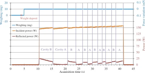
Figure 5. Second experimental run chronogram gathering all the collected measurements. Big Shaker configuration (Cavities 2A & 2B), Mode α. 20 mg calibration and then 200 W RF power at 2442.2 MHz.
0 25 50 75 100 125 150 175 200 225 250 -80 -70 -60 -50 -40 -30 -20 -10 0 10 20 0 5 10 15 20 25 30 Power (W) Weighing (mg) Acquisition time (s) Weighing (mg) Incident power (W) Reflected power (W) Weight deposit Cavity B Cavity A A B A B A 0.1 -0.1 0 Force variation (mN)
Figure 6. Third experimental run chronogram gathering all the collected measurements. Big Shaker configuration (Cavities 2A & 2B), Mode β. 20 mg calibration and then 200 W RF power at 2454.2 MHz.
It can clearly be seen in Figure 4 that the measured weight remains unchanged after the calibration step. It suggests that no EMDrive-like force appears when the cavities are alternately fed with microwave power. A global conclusion will take place at the end of the three runs.
The second measurement run involves the Big Shaker and the mode α, with the highest Q (see Figure 5). As usual, the 20 mg weight is applied, at t ≈ 4 s, and the power-up phase at t ≈ 10 s. It begins with cavity 2B. On the reflected power curve, the cavity switch can be observed more clearly here thanks to the different matchings of the two cavities.
Finally, the third run is performed thanks to the Big Shaker configuration and the mode β, which is the best matched one (≈ −40 dB) (see Figure 6). The calibration step starts here at t ≈ 5 s, and the power is applied at t ≈ 10 s. It begins with cavity 2A. It can be seen in Figure 6 that the cavity switches are barely noticeable because of the very good matching of both cavities.
During all these three runs, the 20 mg weight is measured at 10 mg, and then no weight variation is recorded, even on the last balance digit. Therefore, it can be concluded that no force greater than 0.2 mN is detected by the balance when microwave power is applied. Remembering that at the cavity switches events, the relative force is theoretically doubled, it can be said that no EMDrive-like force above 0.1 mN has been measured with the LAPLACE’s EMDrive experimental setup for these three configurations.
52 Peyre et al.
5. CONCLUSION
This experimental setup allows very fast and straightforward measurements of EMDrive-like forces. No parasitic effect impacts the measurement thanks to the addition of the contactless microwave transition, which can transmit more than 150 W power to the cavities. Only the thermal drift of the resonance still needs to be considered in initializing our protocols.
The considered response time of this setup can be overestimated to 2 seconds. It is limited only by the balance response time and the low inertia of the Shaker configuration. The external power supply combined with the contactless transition minimizes the mass of the device under test. The resulting elimination of the thermal effect of the previous feeding cable makes it possible to consider much faster measurement protocols.
Moreover, the Shaker configuration plays an important role here by creating a double prospective force at the cavity switch events. The creation of easy reading chronograms integrating the calibration step allows a quick and direct interpretation of the measurement results.
We have to emphasize that no EMDrive-like force has been detected above 0.1 mN so far.
The forthcoming use of a new and more sensitive balance (display accuracy of 1 mg, 0.01 mN) will be a significant improvement for the sensitivity of our setup. The final step of our EMDrive study will be the replication of the NASA’s cavities [1]. Until now, no EMDrive-like force has been detected with our setup. Perhaps this is because our cavities do not exhibit the same efficiency as NASA’s (1.2 mN/kW). If they could, the resulting force would be 0.18 mN and would have been detected by our setup. The implementation of the NASA-like cavities is going on, and we will soon be able to compare our results with the other research teams [1, 3].
ACKNOWLEDGMENT
All the authors would like to thank both CNES (French National Centre for Space Studies) and AID (French Innovation and Defense Agency) for funding Hugo Peyre’s work.
REFERENCES
1. White, H., P. March, J. Lawrence, J. Vera, A. Sylvester, D. Brady, and P. Bailey, “Measurement of impulsive thrust from a closed radio-frequency cavity in vacuum,” Journal of Propulsion and
Power, Vol. 33, 830841, Jul 2017.
2. McCulloch, M. E., “Propellant-less propulsion from quantized inertia,” Journal of Space
Exploration, Vol. 7, 1–7, 2018.
3. K¨oßling, M., M. Monette, M. Weikert, and M. Tajmar, “The spacedrive project — Thrust balance development and new measurements of the mach-effect and emdrive thrusters,” Acta Astronautica, Vol. 161, 139152, Aug. 2019.
4. Sokoloff, J., O. Pascal, O. Pigaglio, N. Raveu, and H. Peyre, “Proposal of a handy setup for discriminating parasitic effects for the measurement of impulsive thrust from a microwave cavity,”
Progress In Electromagnetics Research C, Vol. 98, 269–281, 2020.
5. Peyre, H., O. Pascal, J. Sokoloff, K. Elis, O. Pigaglio, and N. Raveu, “High power transmission using contactless microwave transition on an emdrive setup,” Progress In Electromagnetics Research
Letters, Vol. 90, 15–20, 2020.
6. McDonald, M. S., M. W. Nurnberger, and L. T. Williams, “Preparations for thrust measurement and error discussion of the impulse resonant microwave cavity,” Journal of the British Interplanetary