HAL Id: lirmm-02006548
https://hal-lirmm.ccsd.cnrs.fr/lirmm-02006548
Submitted on 4 Feb 2019
HAL is a multi-disciplinary open access
archive for the deposit and dissemination of
sci-entific research documents, whether they are
pub-lished or not. The documents may come from
teaching and research institutions in France or
abroad, or from public or private research centers.
L’archive ouverte pluridisciplinaire HAL, est
destinée au dépôt et à la diffusion de documents
scientifiques de niveau recherche, publiés ou non,
émanant des établissements d’enseignement et de
recherche français ou étrangers, des laboratoires
publics ou privés.
Mechanical Bistable Structures for Microrobotics and
Mesorobotics from Microfabrication to Additive
Manufacturing
Yassine Haddab, Guillaume Aiche, Hussein Hussein, Mouna Ben Salem,
Philippe Lutz, Lennart Rubbert, Pierre Renaud
To cite this version:
Yassine Haddab, Guillaume Aiche, Hussein Hussein, Mouna Ben Salem, Philippe Lutz, et al..
Me-chanical Bistable Structures for Microrobotics and Mesorobotics from Microfabrication to Additive
Manufacturing. MARSS: Manipulation, Automation and Robotics at Small Scales, Jul 2018, Nagoya,
Japan. pp.1-6, �10.1109/MARSS.2018.8481186�. �lirmm-02006548�
Mechanical bistable structures for microrobotics and
mesorobotics
From microfabrication to additive manufacturing
Yassine Haddab, Guillaume
Aiche, Hussein Hussein, Mouna
Ben Salem
LIRMM, Université de Montpellier, CNRS
Montpellier, France. [email protected]
Philippe Lutz
Femto-ST, Université de Bourgogne Franche-Comté, CNRS, ENSMM,
Besançon, France.
Lennart Rubbert, Pierre Renaud
ICube, INSA, Université de Strasbourg, CNRS Strasbourg, France.
Abstract— The use of mechanical bistable structures in the
design of microrobots and mesorobots has many advantages especially for flexible robotic structures. However, depending on the fabrication technology used, the adequacy of theoretical and experimental mechanical behaviors can vary widely. In this paper, we present the manufacturing results of bistable structures made with two extensively used contemporary technologies: MEMS and FDM additive manufacturing. Key issues of these fabrication technologies are discussed in the context of microrobotics and mesorobotics applications.
Keywords— mechanical bistable structures; curved beams; MEMS; FDM additive manufacturing, microrobotics, mesorobotics.
I. INTRODUCTION
One of the major paradigms in the design of very small robots consists in the use of flexible structures. At these scales, the design of mechanisms and micro-assemblies are indeed hard to perform and are generally advantageously replaced by such structures [1]. Bistable structures are mechanical devices that have two stable states. They can be manufactured in conjunction with other parts of the microrobot in a monolithic manner. Using different micro-actuation principles, it is even possible to build complete microrobots on a unique substrate [2].
Bistable structures offer a number of other advantages. They are easy to fabricate and use. They can be fabricated at low cost and built using various manufacturing processes. They are usable for energy or information storage. No energy is required to maintain a structure in one of its two stable states (after pre loading in some cases) [2]. They are easily integrated into complex robotic architectures thanks to their planar shape and compactness [2]. They can be used in open-loop control mode without any sensor.
However, the use of bistable structures in the design of microrobots and mesorobots requires taking into account the modeling of their force-position characteristics and the limitations of the targeted manufacturing process used. In the following, we consider more specifically two microfabrication
technologies: MEMS as it constitutes a technology exploited by many microrobots developed over the last decade, and additive manufacturing (particularly FDM: Fused Deposition Modeling) as a low-cost and widely available contemporary technology. While MEMS are generally made of silicon, a material with very good elastic behavior that facilitates the fabrication of bistable structures, FDM is being used for production of polymer parts, which makes building of bistable structures more difficult because of the unpredictable mechanical characteristics.
In this paper we present elements on the design and operation of bistable structures for microrobotics and miniaturized robots. Section 2 presents the basics of modeling of curved beams, the main components of bistable structures. Section 3 is dedicated to the fabrication of curved beams using MEMS technology and section 4 presents first results using FDM and discusses manufacturing issues using this technology. Section 5 presents examples of bistable structures exploited in the design of microrobots.
II. MODELING OF CURVED BEAMS
A curved beam structure is a component widely used in MEMS as a simple bistable mechanism that combines the advantages of passive holding and compliant mechanisms. Curved beams can be classified in three categories based on the fabrication process [3]:
• Precompressed curved beams, where the beam is fabricated rectilinear then it is compressed [3], [4], [5].
• Prestressed curved beams where during fabrication, the beam is buckled due to residual stresses which are added by heating or oxidation [6], [7].
• Preshaped curved beams where the beam is directly fabricated at the first buckling shape mode without residual stresses [8], [9], [10].
The mechanical behavior of the precompressed curved beam is symmetric between two sides of buckling. However, the Research partially supported by the Investissements d’Avenir (Labex
monolithic constraint in the microfabrication process and the difficulty to set accurately the required buckling dimensions after fabrication make this solution difficult to use in MEMS. The prestressed curved beam makes the integration into a monolithic device easier, but the residual stress is difficult to control by fabrication [3]. For the pre-shaped curved beam, despite the fact that symmetry is lost and that bistability exists only under some conditions, fabrication and integration are simpler, specifically for MEMS applications. A solution used in the literature to improve the symmetry property of pre-shaped curved beams is to use hinged pre-shaped curved beam structure [11], [9], [12]. The thickness of a portion of the beam is then kept very low as compared to the overall beam thickness. This portion is usually designated as the elastic hinge. Local reinforcements are also proposed to be integrated with the pre-compressed length of a curved beam in [13] to adjust the post-buckling state and the snap-through properties.
Few works are found in literature that cover the modeling and design of a preshaped curved beam. Based on Lagrangian approach, Vangbo et al. [14] carried out one of the first studies on precompressed curved beams that takes compressibility into account for small deformations. Self-buckling behavior of microbeams in response to resistive heating was investigated by Chiao et al. [15]. Emam and Nayfeh examine in their studies [16], [17] the dynamics of precompressed curved beams. Cazottes [5] has investigated the bistability of a precompressed curved beam when is actuated either by force or by moment. Elastica models for static and dynamic behavior and experimental validation were presented by Camescasse in his thesis [4]. Chen et al. [18] showed the importance of extensible elastica theory in the modeling of a curved beam.
As for preshaped curved beams, Qiu et al. in [9] presented analytical modeling for the snapping force behavior due to an applied lateral force on the middle length of the beam. Their analytical results were approved by FEM simulations and experiments on microfabricated prototypes. Hussein et al. considered in [19] all the modes of buckling in the modeling of snapping forces and internal stresses. In comparison with FEM simulations and experiments on microfabricated prototypes, the consideration of high modes of buckling results in more accurate modeling mainly for the stress calculation. This calculation is important in order to define the limits on dimensions, especially in miniaturization, that must be respected in the design to avoid exceeding the stress limit during deflection. Park et al. [8] have presented analytical modeling of a preshaped curved beam when it is actuated by Laplace force distributed throughout the beam. In most cases, the action to switch the curved beam is a lateral force applied at the middle of the beam. Otherwise, the action can be also a force applied in different points [4], an electromagnetic field [8], an electrostatic field [20], [21] or moments applied in determined locations on the beam [5], [22]. The curved beam structure is being used in two mechanical forms: free or constrained, meaning that asymmetrical modes of buckling, such as mode 2 can occur or not. The free structure consists generally of a single curved beam, while the constrained structure consists of two or more curved beams that are connected in the middle by a shuttle which is the moving part as shown in Fig. 1.
An example of constrained structure is the bistable device shown in Fig. 2 [12]. Two stop blocks are placed between the
two initial stable sides of the shuttle in three different states (as-fabricated, at position 1 and at position 2). In the as-fabricated state, no residual stress or deformation energy is present, therefore, the shuttle is only stable without holding forces.
Fig. 1. Transition between the two stable positions of two curved beams connected in the middle to a shuttle. Mode 3 appears during transition.
Fig. 2. Bistable structure with hinged curved beams and U-shaped actuators for switching [12].
The stop blocks are physical stops used to block the displacement at one side, to add holding forces at the two stable positions and to define accurately the distance between them. Otherwise, the stable positions can change due to any kind of disturbance (as thermal expansion for example). Therefore, these positions do not change unless an external force is applied in the switching direction that is higher than the holding force.
A preshaped curved beam has the following characteristics presented in Fig. 3: thickness t, depth b, span l, deflection d, beam shape w(x), initial height of buckling h, axial force P and the applied lateral force at the middle f.
Fig. 3. Clamped-clamped curved bistable beam at the initial position and after deflection.
The governing equation of the buckling and post-buckling of a curved beam is developed by Timoshenko in his famous book [23].
d
d + dd = 0 (1)
where E is the Young’s modulus and I is the quadratic moment of the cross section.
The solution of (1) is an infinite sum of buckling shape modes wj where the constant modes aj are calculated in [9], [19]
with a variational calculation after introducing the boundary conditions.
= (2)
The axial force P is constant along the beam. In the as-fabricated
Position, P is equivalent to zero where no residual stress is present in the curved beam. Considering the case of two curved beams attached to a shuttle in the middle as in Fig. 1, the asymmetrical buckling shape mode cannot occur during deflection. Switching the curved beam to the other side of buckling, it becomes compressed and the axial force P increases as long as the beam deflection d gets closer to the middle axis. At a certain limit, P reaches a defined value where bifurcation of solutions occurs in the variational calculation. At this point, the buckling shape mode 3 appears in the shape of the curved beam and P becomes constant. After a certain limit of deflection in the other side of buckling, mode 3 disappears and the axial force P decreases. It is important to mention that P does not reach the limit of bifurcation unless Q = h/t is higher than 2.31.
In terms of the snapping forces, behavior of the curved beam during deflection is nonlinear at the borders while it becomes linear when mode 3 appears in the middle zone of deflection.
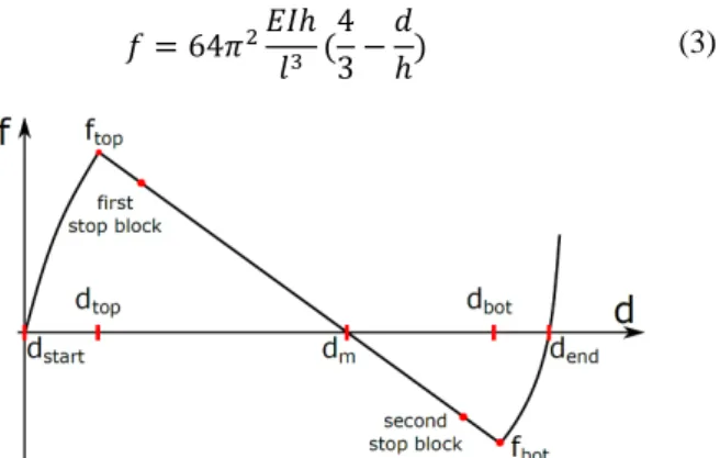
Fig. 4 shows the snapping force curve with respect to deflection
with highlights of remarkable situations. Fabricating a preshaped curved beam makes the behavior asymmetrical. While the two stable positions correspond to minimal energy configuration, one is energy free (as fabricated position) and the second one is non zero energy. In practice, stop blocks that define the holding forces at each stable position and the distance between them are placed in the linear domain in the central part of that characteristic. The expression of the snapping force evolution in that domain is given by:
= 64 ℎ 43 − ℎ (3)
Fig. 4. Snapping force - deflection curve of a preshaped curved beam.
The deflection zone where mode 3 appears is limited between dtop and dbot.
, " = ℎ #2827 ±23 (16 +81 −16 * +1 (4)
The calculation details of the snapping force in the nonlinear domain are presented in [19]. It is however important to mention that the snapping force curve can be approximated to a straight line for high values of Q.
III. MICROFABRICATION OF CURVED BEAMS
The compliant nature of the curved beam offers many advantages such as the absence of friction, backlash, the reduced wear, and low manufacturing costs. The use of silicon exhibits many additional advantages. The silicon has a nearly perfect elastic behavior with highly repeatable motion and without hysteresis and energy dissipation. It possesses in addition a long lifetime with reduced fatigue. This material is widely exploited in MEMS applications, its physical properties are well defined and the fabrication processes with silicon are well developed.
Fig. 5 illustrates an example of the main steps in a fabrication
process. The fabrication is realized on SOI (Silicon On Insulator) wafers which is a common case for MEMS devices.
In the first step, the hard mask in the backside is lithographically patterned and etched using a photomask. In the second step, a gold layer is sputtered, then patterned using wet etching through a photoresist layer which is patterned with a second photomask. This layer serves as a conductive line for supplying the electrical components (electro thermal actuators are used in this device). In the third step, the device layer is patterned lithographically through a third photomask and then etched using a deep reactive ion etching (DRIE) process. In the fourth step, the handle layer is etched by DRIE through the backside SiO2 layer. Finally, the last step consists in releasing
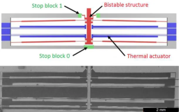
devices from the wafer using HF wet etching. Useless parts fall into the HF solution during etching. Fig. 6 shows an example of obtained device. Microfabrication details and characterization are given in [24].
Fig. 5. Fabrication process steps. SiO2 hard mask etching on the backside (1),
gold layer deposition (2), device and handle layers etched using DRIE process (3-4), structure releasing from the wafer using HF wet etching (5).
Fig. 6. A microfabricated bistable structure including thermal actuators and stop blocks.
IV. 3D PRINTING OF CURVED BEAMS
A. Towards 3D printed devices
Since the last decade, the use of additively manufactured (AM) devices have become more and more important. As it goes adding material along the fabrication, it allows a new way of shaping the manufactured parts, unlike traditional machining. As it allows to prototype quickly, the trial and error method has become efficient, especially with polymer material, even though metal parts could also be manufactured using AM. However, as all manufacturing processes, the designer have to adapt his design to the additive manufacturing constraints.
Focusing on fused deposition modeling (FDM) technology, a widespread AM technology, a filament material is deposed in plane layers. The final device consist of a stack of thin layers.
B. Main process parameters
A filament is made from extruded material, which properties can be characterized. However, once heated and fused in layers, properties can be significantly affected.
In this process, geometry, material and process parameters are tightly linked, as the inner structure of the part depends on how the material is added. Therefore, the manufactured part characteristics such as mechanical properties (esthetic, roughness, etc. could also be mentioned) heavily depends of the process parameters. For many years, researches have been conducted to understand and predict the behavior of the AM parts. Mohamed et al. [25] gave a good overview of the different experimentations done in the state of the art, mainly for ABS material.
Many parameters are analyzed, such as the layer thickness, the deposition orientation, the infill density and patterns, regarding their influence, mainly on mechanical properties.
To understand how it can influence, we have to consider the filament cross section as a homogenous surface, whose mechanical properties could be known, as nominal ones. Considering the angle between the load and the cross section, it is possible to determine the mechanical properties.
Since the FDM allows changing many printing parameters, many of them such as the previous mentioned, affect this resistant surface, regarding the load direction, compared to the orientation of the built structure. Moreover, the fusion between the filaments on the same layer, and between layers is only
partial, meaning that some void is remaining, reducing the resistant surface and then mechanical properties.
Fig. 7. Different infill patterns inducing different mechanical properties of the manufactured part: (left) concentric, (middle) triangle, (right) grid.
As a result, for instance, a linear pattern is stronger in the axis direction, but much weaker in the transverse direction, as delamination phenomena can appear, due to partial fusion between the deposed filaments. Changing pattern allows to improve part resistance in other directions (see Fig. 7). In short, the main engineering challenge is to find the best compromise between all the fabrication possibilities in order to best suit the part requirements. An example is shown in Fig. 8. Researches are conducted to optimize performance. For instance, automatic orientation optimization is presented in [26].
Fig. 8. Tensile characterization sample with different deposed filament orientation.
C. Small size limitations
From microscopic to mesoscopic, scale change could be a challenge, specially adapting the manufacturing tools.
As the stack of fused filament makes the resistance of a part, being in plane or layer structure, small parts using few layers can induce some troubles (see Fig. 9).
Letcher et al. [27] have pointed up the difficulty to predict the mechanical properties. The study of the number of layers of the 3D printed part shows that it is possible to distinguish some trends in the evolution, but it is really hard to predict numerical values without any experiments on the final device.
The automatic toolpath generation could also represent a difficulty to design the device, and it has to be considered during the design step as shown in Fig. 9.
Slicing and toolpath generation softwares use algorithms with predefined strategies. Nevertheless, lack of access to the exact implemented strategies can lead to difficulties for the designer. For instance, it was noticed that some softwares favor the creation of close contours, instead of making open lines, (Fig. 9, B and C). Furthermore, discretization of the filament width is important if precision is needed in really small
dimensions. If width is not a multiple of the filament width (Fig.
9, D), lack or excess of material can be observed (Fig. 9, A). D. 3D printed bistable beam
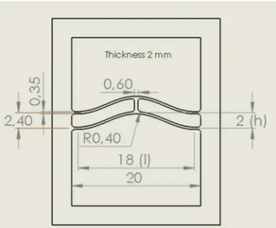
All previous topics are considered to design a 3D printed bistable mechanism. As an example, Fig. 10 shows the dimensions of a double curved bistable beam used for experimental characterization. Dimensions of fabricated samples are under 2% difference compared to nominal values, thanks to printer accuracy.
Fig. 9. Slicing and toolpath generation. Lack of material due to printer resolution: (A) incomplete filling, (B) lack of filling, (C) partial filament fusing inducing weakness, (D) available contour width.
Fig. 10.Main dimensions of a double curved shaped bistable beam sample (all dimensions are in mm).
The design was made according to the model presented in section II. Due to really small dimensions, and technology limitations, the beam part printing parameters can heavily be changed. Infill is 100% and beam width consists of a single fused filament (Fig 9, C), meaning that infill pattern cannot be changed.
The second stable position of the bistable mechanism shows that deformation is different from theory (Fig. 11, right). Actually, some lack of material, some asymmetric filling, and plasticity induce unexpected behavior.
To obtain force and displacement measurements, a dedicated experimental setup was used, composed of a laser-based displacement sensor (Keyence LK-H152) and a calibrated flexure beam of which the displacement gives the force applied thanks to its known stiffness. We apply a displacement using a translational guide table to the double curved bistable beam and the corresponding force is measured using the laser sensor.
Even though, there are clear differences between modeling assumptions and the model, the first experimental characterizations have shown that results are significantly different (Fig. 12). The figure shows a significant error, mainly about extremum force values and the evolution of the force-displacement curve obtained in the experiment. As explained previously, even though it is designed to best fit nominal mechanical properties, the result of geometry, manufacturing parameters and the fused material induces many variations that can be hard to determine without final experiments. These preliminary results show that the greatest care must be taken during the design of mesoscopic structures using FDM technology. The issues described above can be used as a starting point for optimizing the design of the structure.
Fig. 11.Bistable curved beam (left) as shaped stable position, (right) other stable position limited by stop blocks.
Fig. 12.Force-Displacement characterization comparison of a Polycarbonate 3D printed double curved bistable mechanism.
V. APPLICATIONS
In the two previous sections we have described the manufacturing of bistable beams using two widely available technologies: MEMS technology and FDM additive manufacturing. An example of the use of bistable structures for the design of complete microrobots is presented in [2]. A bistable structure is used as an elementary module for the design of a high precision open loop controlled planar microrobots built using MEMS technology. Although more complex, the use of FDM additive manufacturing process is of great interest, including the possibility of manufacturing larger (mesoscale)
structures if devices that can apply large forces or torques are needed. Ion et al. propose meta structures based on bistable units [28]. In particular, microrobots for biomedical applications can be built thanks to the availability of biocompatible materials for FDM process.
VI. CONCLUSION
In this paper, we presented the key concepts for the design and manufacture of bistable structures for microrobotic and mesorobotic applications. Two major manufacturing technologies were considered. The first one is MEMS technology. It makes it possible to obtain behaviors similar to modeling due to the elasticity characteristics of the materials used but it is expensive and requires access to clean room facilities. The second one is FDM 3D manufacturing which opens up a variety of possibilities for low cost devices that can be larger in size. However, the principle of additive manufacturing based on fused filament makes the mechanical behavior of the fabricated device difficult to predict and highly dependent on the trajectory control algorithms used in 3D printers. These issues can be improved either by a methodological/experimental study or by a better control of fabrication parameters. Future work will aim to define design rules for a better match between the theoretical and experimental models, taking into account the constraints of FDM.
ACKNOWLEDGMENT
The authors would like to thank Gilles Bourbon and Patrice Le Moal from FEMTO-ST Institute for their contributions to the simulation, the development of MEMS process and for microfabrication.
REFERENCES
[1] M. Grossard, N. Chaillet, and S Régnier, “Robotique flexible : Manipulation multi-échelle”, Lavoisier, 2013. ISBN 9782746295094. [2] V. Chalvet, Y. Haddab and P. Lutz, A microfabricated planar digital
microrobot for precise positioning based on bistable modules. IEEE - Transactions on Robotics. Vol.29, Issue 3, pp: 641-649. June 2013 DOI: 10.1109/TRO.2013.2240174.
[3] S. S. H. Zaidi, Z. Cherfi-Boulanger, and F. Lamarque, “Contactless energy transfer and control strategy for bistable micro-actuator,” Ph.D Theisis, Université de Technologie de Compiègne, 2011.
[4] B. Camescasse, “Actionnements statique et dynamique dun mecanisme bistable : aspects modlisation, conception et exprimental,” Ph.D. dissertation, Université Pierre et Marie Curie, 2013.
[5] P. Cazottes, “Actionnement des systemes bistables: modlisation et tudes exprimentales,” Thèse de doctorat, Universit Pierre et Marie Curie, Paris, France, 2009.
[6] I. Z. Pane and T. Asano, “Investigation on bistability and fabrication of bistable prestressed curved beam,” vol. 47, p. 5291, 2008.
[7] B. Charlot, W. Sun, K. Yamashita, H. Fujita, and H. Toshiyoshi, “In-plane bistable nanowire for memory devices,” in Design, Test, Integration and Packaging of MEMS/MOEMS, 2008. MEMS/MOEMS 2008. Symposium on. IEEE, 2008, pp. 254–258.
[8] S. Park and D. Hah, “Pre-shaped buckled-beam actuators: theory and experiments,” Sensors and Actuators A: Physical, vol. 148, no. 1, pp. 186–192, 2008.
[9] J. Qiu, J. Lang, and A. Slocum, “A curved-beam bistable mechanism,” vol. 13, no. 2, p. 137146, 2004.
[10] B.-T. Liao, H.-H. Shen, H.-H. Liao, and Y.-J. Yang, “A bi-stable 2x2 optical switch monolithically integrated with variable optical attenuators,” Optics express, vol. 17, no. 22, pp. 19 919–19 925, 2009. [11] B. D. Jensen, M. B. Parkinson, K. Kurabayashi, L. L. Howell, and M. S.
Baker, “Design optimization of a fully-compliant bistable micromechanism,” vol. 48109, p. 2125, 2001.
[12] H. Hussein, V. Chalvet, P. Le Moal, G. Bourbon, Y. Haddab, and P. Lutz, “Design optimization of bistable modules electrothermally actuated for digital microrobotics,” in Advanced Intelligent Mechatronics (AIM), 2014 IEEE/ASME International Conference on. IEEE, 2014, pp. 1273– 1278.
[13] R. Gao, M. Li, Q. Wang, J. Zhao, and S. Liu, “A novel design method of bistable structures with required snap-through properties,” Sensors and Actuators A: Physical, 2018.
[14] M. Vangbo, “An analytical analysis of a compressed bistable buckled beam,” vol. 69, no. 3, p. 212216, Sept. 1998.
[15] M. Chiao and L. Lin, “Self-buckling of micromachined beams under resistive heating,” Microelectromechanical Systems, Journal of, vol. 9, no. 1, pp. 146–151, 2000.
[16] S. A. Emam and A. H. Nayfeh, “On the nonlinear dynamics of a buckled beam subjected to a primary-resonance excitation,” vol. 35, no. 1, p. 117, Jan. 2004.
[17] A. H. Nayfeh and S. A. Emam, “Exact solution and stability of postbuckling configurations of beams,” vol. 54, no. 4, p. 395408, Dec. 2008.
[18] J.-S. Chen and H.-W. Tsao, “Static snapping load of a hinged extensible elastica,” Applied Mathematical Modelling, 2013.
[19] H. Hussein, P. Le Moal, G. Bourbon, Y. Haddab, and P. Lutz, “Modeling and stress analysis of a pre-shaped curved beam: influence of high modes of buckling,” International Journal of Applied Mechanics, vol. 7, no. 04, p. 1550055, 2015.
[20] S. Krylov and N. Dick, “Dynamic stability of electrostatically actuated initially curved shallow micro beams,” Continuum Mechanics and Thermodynamics, vol. 22, no. 6-8, pp. 445–468, 2010.
[21] F. Tajaddodianfar, M. H. Yazdi, and H. N. Pishkenari, “Dynamics of bistable initially curved shallow microbeams: Effects of the electrostatic fringing fields,” in IEEE/ASME International Conference on Advanced Intelligent Mechatronics AIM, 2014, p. 12791283.
[22] B. L. Stoimenov, J. M. Rossiter, and T. Mukai, “Manufacturing of ionic polymer-metal composites (IPMCs) that can actuate into complex curves,” in The 14th International Symposium on: Smart Structures and Materials & Nondestructive Evaluation and Health Monitoring. International Society for Optics and Photonics, 2007, pp. 65 240T65240T–11.
[23] S. Timoshenko, Theory of elastic stability. McGraw-Hill, 1961. [24] Q. Chen, Y. Haddab, and P. Lutz, “Microfabricated bistable module for
digital microrobotics,” J. Micro-Nano Mechatron., vol. 6, pp. 1–12, 2010. [25] O. A. Mohamed, S. H. Masood, and J. L. Bhowmik, “Optimization of fused deposition modeling process parameters: a review of current research and future prospects”, Adv. Manuf. Springer-Verlag, 2014, DOI 10.1007/s40436-014-0097-7.
[26] E. Ulu, E. Korkmaz, K. Yay, O. B. Ozdoganlar, and L. B. Kara “Enhancing the Structural Performance of Additively Manufactured Objects Through Build Orientation Optimization”, Journal of Mechanical Design, Vol. 137, 2015, DOI: 10.1115/1.4030998.
[27] T. Letcher, B. Rankouhi, and Sina Javadpour, “Experimental study of mechanical properties of additively manufactured ABS plastic as a function of layer parameters”, Proceedings of the ASME 2015 IMECE, Houston, Texas, USA.
[28] A. Ion, L. Wall, R. Kovacs, and P. Baudisch, “Digital Mechanical Metamaterials”, Proceedings of the 2017 CHI Conference on Human Factors in Computing Systems, Denver, Colorado, USA.
![Fig. 2. Bistable structure with hinged curved beams and U-shaped actuators for switching [12]](https://thumb-eu.123doks.com/thumbv2/123doknet/14353403.501341/3.892.462.835.347.686/bistable-structure-hinged-curved-beams-shaped-actuators-switching.webp)