1 Abstract— This paper puts forward an adaptive cold start strategy for a proton exchange membrane fuel cell (PEMFC) based on maximum power mode. The proposed strategy consists of a water evacuation process after PEMFC shutdown and a self-heating process at PEMFC cold startup. To maximize the performance of the suggested strategy, an optimal operating condition for the cold start procedure is sought first. In this respect, an experimental parametric study is performed to explore the impact of fan velocity, micro-short circuit, anode pressure, and purge procedure on the PEMFC cold start performance. After laying down the proper conditions, the proposed cold start procedure is implemented on a test bench for experimental validations. The self-heating process is based on an online adaptive algorithm that maximizes the PEMFC’s internal heat depending on its operating parameters’ variation. In fact, this algorithm attempts to keep the current density at high levels, leading to PEMFC’s performance improvement achieved by membrane hydration and temperature increase. The experimental results confirm the effectiveness of the proposed strategy, which presents a fast and cost-effective PEMFC’s cold start.
Index Terms— Adaptive control, Cold start strategy, Kalman filter, Proton Exchange Membrane Fuel Cell, Vehicular applications
I. INTRODUCTION
RANSPORTATION is a major pollution contributor,
generating substantial quantities of nitrogen oxides, carbon monoxide, and other pollutants [1]. A wide range of technological solutions, such as hybrid electric vehicles (HEVs), battery vehicles, and fuel cell hybrid electric vehicles (FCHEVs) offer the potential to mitigate these impacts [2]. Among them, FCHEVs, which use a proton exchange membrane fuel cell (PEMFC) as the primary source and a battery pack as the secondary one, have gained great public and governmental recognition [3]. FCHEVs can be refueled in a few minutes, and used for a wide driving range [4, 5]. In addition, they can reduce dependency on fossil fuels and offer potential reductions of greenhouse gases, especially when fueled with hydrogen from electrolysis or biomass [6]. Although FCHEVs are becoming increasingly important in the automotive sector, their market penetration and economic viability depend on the technological progress in the area of fuel cell lifetime, cost decline, and resolving the cold start issue in countries with cold weather conditions [7, 8].
PEMFC is an electro-chemical device that generates electricity by discharging heat and water. At cold temperature, the produced water freezes on the cathode and anode catalyst layer, which can block the passage of oxygen and hydrogen [9]. Furthermore, the water absorbed by the membrane can freeze, which slows down the electro-chemical reactions [9]. These phenomena cause a voltage and power drop, leading to the failure of the cold start and acceleration of the PEMFC degradation [10, 11].
In vehicular applications, a number of countries and institutions have imposed specific requirements for the PEMFC’s cold startup. For instance, the US department of energy (DOE) has targeted a swift startup from -20 °C in less than 30 s while consuming a low of 5 MJ of energy in 2020 [12]. Moreover, they have aimed at a successful startup at -20 °C without utilizing an external heating source [12]. The European Union attempts to reach an effective cold startup at -25°C while sustaining a satisfying proton conductivity (over 10 mS.cm-1 at -20°C) [13]. Several studies have also proposed different strategies to improve the cold start quality of the PEMFC. These strategies fall into two groups of "Keep warm" and "Thaw at start" [14]. The former employs a thermal energy source to keep the PEMFC temperature near to its desirable range during the FCHEV parking time [15-18]. This methodology enhances the cold startup ability by protecting the PEMFC stack from freezing phenomenon. It can be effective for applications where the parking period is short and known a priori. However, when the parking period is long and not known, this method might become expensive concerning the required energy for heating the stack. The methods based on "Thaw at start" do not consume any energy during the parking time. Nevertheless, they demand a specific heat flow during the cold startup to rise the stack temperature from subfreezing condition to its desired operation range [19-32].
The strategies based on "Thaw at start" principle can be grouped into two categories of ''Assisted cold start strategy'' and ''self-cold start strategies'' according to the heating source [33, 34]. The first one requires an external heating source, such as heating element, hot air fan, battery, and catalytic burner, to escalate the PEMFC stack temperature during the startup [19-23]. This category of strategies improve the heating time at the cost of decreasing the energy efficiency and increasing the cost of the system [33]. Moreover, the DOE has demanded an effective approach without the use of an external heating source [35]. Therefore, several researchers have turned attention to the development of ''self-cold start strategies''. These strategies are based on two steps: 1) purging procedure during the shutdown
An Online Self Cold Startup Methodology for
PEM Fuel Cells in Vehicular Applications
A. Amamou, Member, IEEE, M. Kandidayeni, Member, IEEE, S. Kelouwani, Senior Member, IEEE,
L. Boulon, Senior Member, IEEE
T
Copyright (c) 2015 IEEE. Personal use of this material is permitted. However, permission to use this material for any other purposes must be obtained from the IEEE by sending a request to [email protected]
A. Amamou1, M. Kandidayeni1, S. Kelouwani1 and L. Boulon1, 1 : Hydrogen Research Institut, University of Quebec at Trois-Rivieres, Trois-Rivières, QC G9A 5H7. CANADA
(e-mail: [email protected] )
POSTPRINT VERSION. The final version is published here: Amamou, A., Kandidayeni, M., Kelouwani, S., & Boulon, L. (2020). An Online Self Cold Startup Methodology for PEM Fuel Cells in Vehicular Applications. IEEE Transactions on Vehicular Technology, 69(12), 14160-14172. http://dx.doi.org/10.1109/TVT.2020.3011381
© 2020 IEEE. Personal use of this material is permitted. Permission from IEEE must be obtained for all other uses, in any current or future media, including reprinting/republishing this material for advertising or promotional purposes, creating new collective works, for resale or redistribution to servers or lists, or reuse of any copyrighted component of this work in other works.
2 to reduce water accumulation and decrease ice formation in the cathode catalyst layer; 2) a heating process during the start-up based on a heating solution. The methods based on self-heating employ the heat produced by the exothermic reaction and are divided into three types: galvanostatic startup (fixing the PEMFC current to the best current regarding the production of the heat inside PEMFC), potentiostatic startup (setting the PEMFC voltage to the best voltage which maximizes the exothermic heat production), and the maximum power mode startup.
Hishinuma et al. [30] and Lin et al. [27] propose a self-cold start strategy, based on purge procedure at shutdown and galvanostatic mode at start-up. This strategy is effective for a cold start from -5°C but ineffective for lower temperatures. In order to increase the heat flux supplied by the galvanostatic solution and to provide a self-cold start from -20°C, Guo et al. [26] introduce an O2/H2 mixture on the anode side during the
cold start. The majority of studies regarding the self-cold start strategy propose purging the PEMFC after shutdown and considering the potentiostatic mode at startup [24, 25, 28, 36]. This strategy is shown to be effective at cold startup from -20°C. Qing et al. [37] propose a self-cold start strategy based on the PEMFC maximum power mode, and compare it with both potentiostatic and galvanostatic modes for a cold start from -20°C. They demonstrate that the maximum power mode is capable of balancing the heat production and the ice formation, resulting in an enhanced cold start survivability compared to the galvanostatic and potentiostatic solutions [37]. The potentiostatic, galvanostatic, and maximum power modes are efficient in terms of energy consumption, but heating time remains long for automotive applications [33].
One common issue of the above-discussed methods is that they are based on a set of precomputed parameters which are prone to alteration as the PEMFC undergoes performance drifts owing to operating conditions variation (temperature, membrane hydration, etc) and stack degradation. The degradation of a PEMFC is typically defined by the loss of voltage, which directly affects the rated power, through time [38, 39]. Moreover, the extreme ambient conditions, such as subzero temperature, influence the output power of the PEMFC which in turn negatively impact the performance of the mentioned internal heating methods. So far, no PEMFC model has been proved to be able to accurately consider the degradation and the effect of ambient as well as the operating conditions, and it is still a study limitation in the literature. Therefore, some researches have been conducted to track the performance drifts of a PEMFC system in real-time based on extremum seeking strategies. These strategies offer two solutions. The first one mainly depends on the use of hill climbing methods [40, 41]. For instance, in [40], a fractional-order strategy is proposed to find an extremum value of a static nonlinear curve using a gradient optimization process. This strategy applies a periodic perturbation signal to the system input and then revises it toward the targeted objective point. Such methods are interesting due to their straightforward implementation. However, the perturbation signal is not simple to select during the cold startup of the PEMFC as it can increase the heating time and decrease the overall performance. The second solution is based on the use of an online parameter estimator coupled with an optimization algorithm [42, 43]. In
this respect, the estimator updates the parameters of the mode online and then the required characteristics, such as maximum power, is extracted from the updated model. In [44], an adaptive cold start strategy is proposed to cope with the PEMFC parameters variation and to improve the cold start performance. However, the utilized model in this study does not take into account the temperature which is an important factor in cold start procedure.
The main objective of this paper is to develop an adaptive self-cold start strategy based on the maximum power mode of the PEMFC. In this regard, firstly, a parametric study is conducted to investigate the influence of PEMFC main parameters (anode pressure, fan speed, purge and micro short-circuit) over cold start performance. Afterwards, the adaptive cold start strategy is developed using a multi-input semi-empirical model of the PEMFC and Kalman filter, and its performance is experimentally validated by using three PEMFCs with different levels of degradation. Compared to other similar works, the main contributions of this paper are as follows:
• Performing a detailed parametric study to find the best operating parameters (anode pressure, fan speed, purge and micro short-circuit) for doing the PEMFC cold startup process (compared to [37, 44]). • Employing a multi-input semi-empirical PEMFC
model along with Kalman filter for accurate online estimation of maximum power in subfreezing condition (compared to [37, 44, 45]).
• Validating the performance of the proposed adaptive cold startup strategy by using three 500-W PEMFCs with different levels of degradation (compared to [37, 44]). .
The rest of the paper is organized as follows. Section II details the parametric study. Section III explains the adaptive cold start strategy. Section IV discusses the experimental results, and finally, the conclusion is given in section V.
II. PARAMETRIC STUDY
During a self-cold startup, it is necessary to select the operating parameters in a way to maximize the generation of the heat inside the stack, which has a direct effect on the heating time. This section deals with the analysis of four important system parameters, namely anode pressure, fan velocity, purge, and short-circuit during the cold startup process to clarify the impact of each factor on the heating time. In this respect, the developed experimental set-up for testing the effect of each system’s parameter is explained first. Subsequently, the reason for selecting each parameter is discussed. Finally, the experimental protocol, and the results regarding the influence of parameters on the cold startup are presented.
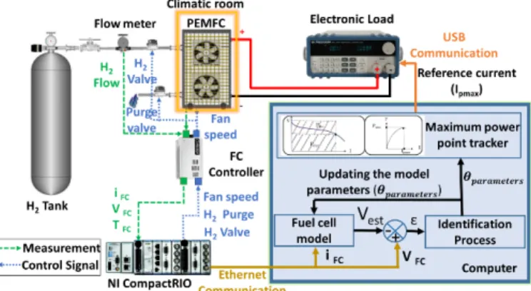
A. Test bench
The utilized test bench for the purpose of this work is presented in Fig. 1. This test bench includes an H500 Horizon open cathode PEMFC. It is self-humidified with a nominal power of 500 W (rated performance: [email protected]), and 36 cells. This PEMFC has a dead-ended anode (DEA) configuration, which is fed by dry hydrogen at a controlled inlet
3 pressure. A DEA configuration benefits from lower cost, volume, and weight compared to a flow-through system since it does not need a hydrogen recirculation loop and its auxiliary modules, including a pump, humidifier, and water separator [46]. However, there are also some issues regarding the DEA operation. Water accumulates in the anode catalyst layer and gas diffusion layer. Moreover, nitrogen of the air in the cathode side is added to the hydrogen gas in the anode channels by passing through the membrane [47]. Consequently, the anode side needs to be purged recurrently in order to remove accumulated water and nitrogen. At subzero temperature, the accumulated water can also freeze and fail the cold startup. Therefore, purging the residual water after shutdown and during PEMFC operation is necessary. The utilized PEMFC in this study is equipped with a purge valve to evacuate the produced water from the anode side. The purge procedure is divided into two phases. The first phase is related to the activation of the purge valve for 10 ms every 10 s during the operation of the PEMFC. This phase is common for all PEMFCs as it allows the evacuation of water and impurities generated during the normal operation. The second phase is related to winter condition and consists in purging the PEMFC after shutdown for 90 s. Due to the open-cathode nature of the system, the cathode is always exposed to relatively dry ambient air. This configuration requires a system design which can keep the water in the MEA to achieve fast humidification [46]. Therefore, the bipolar plate on the anode side does not feature flow channels but an interdigitated flow field, which is integrated directly into the GDL. Moreover, fans are operated at high speed for a few seconds before each PEMFC shutdown to flush residual water out of cathode. It is also worth noting that both anode and cathode provide micro-porous layers (MPL) between GDL and CL, which avoid flooding phenomena and provide more space for ice formation. The anode and cathode flow field geometry of the studied stack as well as the structure of the diffusion layers have been discussed in details by Strahl et al. [48].
The minimum operating temperature of this PEMFC is around 0°C according to the manufacturer. It is equipped with two cooling fans to control the PEMFC temperature and to supply oxygen to the cathode side. Five thermistors are installed on different sides of the stack to measure the PEMFC temperature. One sensor is located in the center, two sensors are at the top-left and top-right corners, and two sensors are at the bottom-left and bottom-right corners. The stack temperature is equal to the average of all measurements. On the cathode side, the pressure is equal to the atmospheric pressure (1 bar). The pressure difference between the anode and the cathode must not exceed 0.6 bar to avoid membrane damage. PEMFC can also be short-circuited during normal operation, which promotes water production and heat. The generated water and heat generally favor the humidification of the membrane and improve the performance of the PEMFC.
The control of PEMFC auxiliaries, such as purge valve, anode pressure, fan speed, hydrogen valve, and short circuit, is performed through an NI CompactRIO programmable controller 9022. A programmable load with a maximum power of 1200 W is connected to the PEMFC to emulate the behavior of an electric motor. The PEMFC is placed inside a climatic room to simulate winter conditions. The volume of the climatic room is 0.39 m3 (85cm × 55cm × 85cm), oxygen consumption
rate is 3.5 L /min, and the amount of oxygen in the climatic room is 81.7 L, which is sufficient for the conducted tests.
Fig. 1. The developed experimental setup for the cold startup test.
B. Selected parameters
The studied parameters are as follows:
• Fan speed: In the utilized open cathode PEMFC of this work, cooling fan has a dual role of controlling the amount of oxygen supplied to the stack and the regulation of temperature. Therefore, the speed of the fan is tuned depending on the requested power from the PEMFC and the stack temperature [49]. During the cold startup, it is desirable to increase the heat generation inside the stack for having a successful power rise. Therefore, it is important to determine the minimum fan speed which is sufficient for the reaction and cooling. A high fan speed is not recommended during the cold startup as it decreases the generation of the heat. To verify this choice, the cold start performance is studied by selecting two levels of 34% and 43% for the operation of the cooling fan duty cycle. 34% is the minimum required duty cycle preset in the controller of the PEMFC by the manufacturer, and 43% is just a higher duty cycle to show that increasing the fan speed is undesirable for the cold startup performance.
In an open cathode PEMFC, the airflow generated by the minimum duty cycle guarantees a high oxygen stoichiometry ratio at the rated power [50, 51]. Concerning the employed PEMFC in this paper, the cathode stoichiometry is calculated by [50]: 𝑆𝑆𝑂𝑂2 = 𝑛𝑛̇𝑖𝑖𝑛𝑛 𝑂𝑂2 𝑛𝑛̇𝑐𝑐𝑐𝑐𝑛𝑛𝑐𝑐𝑂𝑂2 � =0.21(𝜌𝜌 𝑎𝑎𝑖𝑖𝑎𝑎𝑄𝑄𝑎𝑎𝑖𝑖𝑎𝑎 𝑀𝑀𝑎𝑎𝑖𝑖𝑎𝑎 � ) 𝑁𝑁𝑐𝑐𝑐𝑐𝑐𝑐𝑐𝑐4𝐹𝐹𝐼𝐼 � (1)
where 𝑆𝑆𝑂𝑂2 is the oxygen stoichiometry, 𝑛𝑛̇𝑖𝑖𝑛𝑛𝑂𝑂2 is the amount of
oxygen supplied to the PEMFC, 𝑛𝑛̇𝑐𝑐𝑐𝑐𝑛𝑛𝑐𝑐𝑂𝑂2 is the consumed
oxygen in the electrochemical reaction, 𝜌𝜌𝑎𝑎𝑖𝑖𝑎𝑎 is the air
density, 𝑄𝑄𝑎𝑎𝑖𝑖𝑎𝑎 is the air flow, 𝑀𝑀𝑎𝑎𝑖𝑖𝑎𝑎 is the air molar mass, 𝑁𝑁𝑐𝑐𝑐𝑐𝑐𝑐𝑐𝑐
is the number of cells, and 𝐹𝐹 is the Faraday constant. In (1), the only undefined parameter is the airflow (𝑄𝑄𝑎𝑎𝑖𝑖𝑎𝑎), which is
obtained using the presented experimental measurements in Fig. 2.
4
Fig. 2. Cooling fan characteristics, a) fan voltage with respect to duty cycle, and b) air flow with respect to fan voltage.
According to (1) and Fig. 2, even at the minimum duty cycle of the fan (34%), a stoichiometry of around 33 is reached at the rated performance of the PEMFC ([email protected]).
• The micro-short circuit: The micro short-circuit provides a current peak for 10 ms every 10s in the utilized PEMFC stack. Activating the micro-short circuit leads to the increase of heat and water generation inside the PEMFC, which can improve the PEMFC cold startup. In normal operation, it is recommended to activate the micro-short circuit to enhance the performance of the stack in applications where the stack is not frequently used. However, the influence of this parameter on cold start performance has not been considered. Herein, the cold start performance is inspected with and without performing the micro short-circuit.
• Purging after shutdown: Literature study shows that purging the PEMFC after shut down reduces ice formation on the cathode which in turn improves the PEMFC cold start [52, 53]. In this regard, the influence of purging on the heating time is of interest in this study. To justify the effect of purging, the cold startup performance is investigated with and without purging the PEMFC after shutdown.
• Anode pressure: The performed analysis of the anode pressure effect on the cell potential in [54] shows that the increase of hydrogen partial pressure to a certain range leads to the reduction of concentration loss which increases the cell potential. In fact, rising the pressure level in the anode side leads to the increase of hydrogen permeation through the membrane which promotes the reaction at the cathode and resulting in the increase of voltage and temperature. However, further rise of the hydrogen partial pressure results in lower membrane hydration owing to the reduction of water vapor diffusivity. In this study, the cold startup is tested for two anode pressure levels of 0.45 bar and 0.6 bar. 0.45 bar corresponds to the minimum pressure recommended by the manufacturer, and 0.6 bar is the maximum authorized pressure.
With respect to the discussed matters, two levels are considered for each parameter in this work. Therefore, the number of possibilities comes to 16 for four parameters with two levels. More levels for each factor could be selected. However, the number of possibilities would become very high. Moreover, heuristically, the selection of more levels is not required considering the aforementioned explanation for each parameter. The 2k model (k factors with 2 levels each)
is the most widely used model as it allows several factors to be inspected at no extra cost [55]. Moreover, the
experimental tests show that two levels are adequate for adjusting the parameters.
C. Experimental protocol
An experimental protocol has been developed to determine the parameters that minimize the heating time. In this work, heating time refers to the required time for the evolution of the PEMFC temperature from -20 °C to the stack minimum operating temperature (0 °C). The experimental plan is composed of 16 tests representing all possible combinations of the discussed parameters. Each test has three or four steps: 1. Normal operation of PEMFC at the current level of 10 A and an ambient temperature of 20 °C for 15 minutes.
2. After 15 minutes of normal operation, the PEMFC is placed in the chamber of -20 °C for 8 hours. The 8-hour conditioning time corresponds to the required time to stabilize the temperature of the PEMFC at -20 °C.
3. At the beginning of the conditioning phase, the PEMFC is still hot and most of the produced water is in a gaseous state. When the PEMFC cools down and most of the water turns to a liquid state (around 5°C), the purge valve is activated for 90 seconds to evacuate the residual water. Purging temperature and duration are selected based on [33, 56-58]. This step presents ‘’Purging at shutdown’’ factor.
4. After 8 hours of conditioning at -20 °C, the PEMFC cold startup is performed by asking a constant voltage of 15V. The constant voltage mode is chosen to keep the same electrical parameters for all the tests. The constant voltage value (15V) is in fact the rated voltage of the tested PEMFC at -20°C. The heating time is reported for each test. Each test has been repeated twice to ensure the accuracy of the results.
D. Results analysis
The factorial experiment is used to analyze the impact of the selected system parameters on the heating time. This experiment clarifies the effect of each parameter and the effect of interactions between parameters on the heating time. Minitab software is used for the design and analysis of the factorial experiment. The result of the factorial experiment is presented by a Pareto chart of effects in Fig. 3. The Pareto chart shows the absolute values of the normalized effects, ordered from the highest to the lowest. This diagram also includes a reference line which determines the statistically significant parameters. In Fig. 3, the bars that intersect the reference line are statistically important. That means the bars representing the "fan speed" (A) "purging at shutdown" (B), "micro short-circuit" (C) and "anode pressure" (D) intersect the reference line at 1.4 and have substantial impact on the heating time. Since the Pareto plot shows the absolute value of the effects, the level of parameters to increase or decrease the heating time cannot be determined.
5
Fig. 3. Pareto chart of the parameters’ effect on the heating time.
In this respect, the normal probability plot of the parameters’ effect is presented in Fig. 4 to illustrate the importance and direction of effects. The normal probability plot indicates the position of the normalized effects with respect to the red line, which represents the case where all the effects would be 0. The positive effects increase the response when the factor state changes from the low level to the high level. Negative effects decrease response when factor state changes from low level to the high level. Effects farthest from 0 are statistically more significant. Fig. 4 confirms that the effects of A, B, C and D are statistically substantial. Concerning the direction of the effects, the parameters A and C have a positive normalized effect. As these parameters go from the low level to the high level, the heating time increases. The parameters B and D have negative normalized effects. When these two factors go from the low level to the high level, the heating time decreases.
Fig. 4. Normal probability plot of the parameters’ effects on the heating time.
To summarize, by decreasing the fan speed from high level to low level, the heating time considerably decreases (179 s). Therefore, during PEMFC cold start, the fan speed should be fixed at the minimum level which provides enough air to operate the PEMFC in the whole power range. Regarding the micro short-circuit, its activation increases the heating time (8 s). This increase is due to the fact that the water produced by micro short-circuit freezes at low temperature and affects the cold start performance. On the other hand, purging the PEMFC during shutdown reduces the heating time (11 s). Many studies
have shown the effectiveness of the purge procedure in cold startup as it prevents the freezing of the residual water [59-62]. Concerning the anode pressure, the Pareto diagram shows that the pressure rise from 0.45 bar to 0.6 bar decreases the heating time (7 s). Therefore, the anode pressure should be set at its maximum authorized level. Table I shows the most suitable parameters for developing a cold startup strategy. These parameters are used in the adaptive cold startup strategy discussed in the next section.
TABLE I
THE TUNED OPERATING PARAMETERS OF THE PEMFC SYSTEM FOR COLD STARTUP PROCESS
Parameters Value or state
Fan velocity Minimum operational fan velocity
Micro short-circuit (C) Disabled Purge after Shutdown (P) Enabled
Pressure (S) The maximum authorized pressure
III. ADAPTIVE COLD START STRATEGY
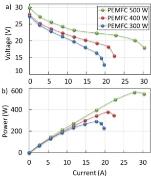
A. Maximum power mode
During the cold startup, it is important to maximize the generated exothermic heat inside the PEMFC to rapidly increase the stack temperature. Fig. 5 shows that as the drawn current from the PEMFC increases, more heat is generated by the exothermic reaction. However, reaching very high current level (low voltage level) can also result in the failure of the PEMFC cold start [24]. In fact, at high current levels, the concentration of oxygen and hydrogen decreases which leads to gases’ partial pressure drop inside the PEMFC [63, 64]. This phenomenon causes a drop in cell voltage commonly known as concentration loss [9]. The PEMFC stack has a current threshold (corresponding to the maximum power) and exceeding this limit results in an increase in concentration loss and PEMFC degradation [33]. Therefore, it is suggested to operate the PEMFC at its maximum power (Pmax) during cold
startup. This mode of operation does not require the external heating sources and maximizes the residual heat and electrical power while avoiding concentration loss and degradation of the stack. The maximum power mode is one of the most effective self-cold start strategies because it can better balance the heat generation and ice formation, leading to improved cold start survivability [37, 44]. Nevertheless, it cannot be assumed that the PEMFC maximum power is constant during a cold startup since it is strongly influenced by degradation and the variation of operating conditions, such as pressure, temperature, and so forth [45, 65-67]. Moreover, some phenomena, including the increase of concentration loss due to the ice formation in the cathode catalyst and the reduction of ohmic and concentration loss due to the generated heat [33], affect the magnitude and location of the maximum power in a PEMFC. Therefore, it is important to identify the PEMFC maximum power online during the cold startup.
6
Fig. 5. Polarization and power curves of a 500-W PEMFC.
In this work, an adaptive process is developed to identify the PEMFC maximum power depending on PEMFC operating conditions and health state. This adaptive process is based on a recursive identification algorithm that updates the parameters of a PEMFC semi-empirical model in order to plot the PEMFC power curve in real time. The maximum power point is updated in real time using a maximum power point tracker algorithm, and the current corresponding to the maximum power is imposed to the PEMFC during the cold start. The flow chart of the global cold start strategy is shown in Fig. 6.
Fig. 6. Flow chart of the global cold start strategy.
B. Purge procedure at shutdown
In automotive applications, purge duration is very important because additional energy is consumed during the purge process and must be controlled to prevent the membrane dehydration [68]. Several studies have shown that a short purge time does not eliminate enough residual water which in turn increases the freezing potential inside the stack [69]. On the other hand, a long purge time increases the membrane resistance, which limits the PEMFC current and thus reduces the produced heat [70]. Based on literature, it is confirmed that the purge duration of 90-120 s is suitable for FCHEVs [71, 72]. In this respect, the duration of purge is set to 90 s in the adaptive cold start strategy of this paper.
The PEMFC temperature is also crucial for the effectiveness of purge procedure [56, 73]. After shutdown, the PEMFC is still warm and the produced water inside the PEMFC is in gaseous state. Therefore, it is preferable to wait until the PEMFC temperature decreases and water state changes from the gaseous to liquid. Once the water is in a liquid state, it must be purged before the PEMFC temperature reaches the freezing temperature. Based on [56], the PEMFC purge temperature is set to 5°C.
C. Adaptive algorithm for maximum power identification
The heating procedure is based on an adaptive PEMFC current control to maximize the produced exothermic heat during cold start. This process is performed in 3 steps, shown in Fig. 7, as follows:
1. Updating the parameters of a PEMFC model using an online identification algorithm to plot the present state PEMFC power curve.
2. Finding the operating current level corresponding to the PEMFC’s maximum power. This operating current is updated every 100 ms.
3. Applying the identified current level to the PEMFC stack.
It should be noted that as soon as the PEMFC temperature reaches 0°C, the control process will be stopped.
7 Fuel cell semi-empirical model
The choice of the semi-empirical model is crucial for the identification process because the model structure greatly influences the accuracy of the estimation. In [45], a comparative study of different semi-empirical models is performed and concluded that the model proposed by Amphlett et.al [74] is adequately precise for reproducing the PEMFC electrochemical behavior. Amphlett model estimates the PEMFC output voltage by taking several inputs (current, pressure, and temperature) into account. This model can be presented by the following equations. 𝑉𝑉𝑓𝑓𝑐𝑐= 𝑁𝑁 𝑉𝑉𝑐𝑐𝑐𝑐𝑐𝑐𝑐𝑐 𝑉𝑉𝑐𝑐𝑐𝑐𝑐𝑐𝑐𝑐= 𝐸𝐸𝑁𝑁𝑐𝑐𝑎𝑎𝑛𝑛𝑐𝑐𝑁𝑁+ 𝜂𝜂𝑎𝑎𝑐𝑐𝑁𝑁+ 𝜂𝜂𝑐𝑐ℎ𝑚𝑚𝑖𝑖𝑐𝑐+ 𝜂𝜂𝑐𝑐𝑐𝑐𝑛𝑛 𝐸𝐸𝑁𝑁𝑐𝑐𝑎𝑎𝑛𝑛𝑐𝑐𝑁𝑁= 1.229 − 0.85 × 10⁻³�𝑇𝑇𝑓𝑓𝑐𝑐− 298.15� + 4.3085 × 10⁻⁵𝑇𝑇 𝑓𝑓𝑐𝑐[𝑙𝑙𝑛𝑛(𝑃𝑃𝐻𝐻2) + 0.5𝑙𝑙𝑛𝑛 (𝑃𝑃𝑂𝑂2)] � 𝜂𝜂𝑎𝑎𝑐𝑐𝑁𝑁 = 𝜉𝜉1+ 𝜉𝜉2𝑇𝑇𝑓𝑓𝑐𝑐+ 𝜉𝜉3𝑇𝑇𝑓𝑓𝑐𝑐𝑙𝑙𝑙𝑙𝑙𝑙(𝐶𝐶𝐶𝐶2) + 𝜉𝜉4𝑇𝑇𝑓𝑓𝑐𝑐𝑙𝑙𝑙𝑙𝑙𝑙(𝑖𝑖𝑓𝑓𝑐𝑐) 𝐶𝐶𝐶𝐶2=5.08 × 10⁶ 𝑒𝑒𝑒𝑒𝑒𝑒(− 498 𝑇𝑇𝑃𝑃𝑂𝑂2 𝑓𝑓𝑐𝑐 ⁄ ) 𝜂𝜂𝑐𝑐ℎ𝑚𝑚𝑖𝑖𝑐𝑐 = −𝑖𝑖𝑓𝑓𝑐𝑐𝑅𝑅𝑖𝑖𝑛𝑛𝑁𝑁𝑐𝑐𝑎𝑎𝑛𝑛𝑎𝑎𝑐𝑐 = −𝑖𝑖𝑓𝑓𝑐𝑐�𝜇𝜇1+ 𝜇𝜇2𝑇𝑇𝑓𝑓𝑐𝑐+ 𝜇𝜇3𝑖𝑖𝑓𝑓𝑐𝑐� 𝜂𝜂𝑐𝑐𝑐𝑐𝑛𝑛= 𝐵𝐵𝑙𝑙𝑙𝑙𝑙𝑙 �1 −𝐽𝐽𝐽𝐽𝑓𝑓𝑐𝑐 𝑚𝑚𝑎𝑎𝑚𝑚�
Where, Vfc is the PEMFC output voltage (V), Vcell is the cell
output voltage (V), N is the number of cells, ENernst is the
reversible cell potential (V) [75], Vact is the activation loss (V),
Vohmic is the ohmic loss (V), Vcon is the concentration loss (V), T
is the stack temperature (K), PO2 is the cathode oxygen partial
pressure (N m-2), PH2 is the anode hydrogen partial pressure (N
m-2), Ɛn (n=1..4) are the semi-empirical coefficients based on
electrochemistry, fluid mechanics and thermodynamics [76],
CO2 is the oxygen concentration (mol cm-3), ifc is the PEMFC
operating current (A), Rinternal is the internal resistor (Ω), µn
(n=1…3) are the parametric coefficients, B is a parametric coefficient (V), J is the actual current density (A cm-2), and Jmax
is the maximum current density (A cm-2).
As explained in [77, 78], assuming that the PEMFC is a perfect isolated system, the entropy change becomes zero and the Gibbs free energy will be equal to the variations of enthalpy (∆𝐻𝐻𝑓𝑓). In this case, the maximum voltage (𝑉𝑉𝑚𝑚𝑎𝑎𝑚𝑚) given by the
overall conversion of enthalpy into electrical energy is obtained by:
𝑉𝑉𝑚𝑚𝑎𝑎𝑚𝑚= −∆𝐻𝐻𝑛𝑛𝑒𝑒𝐹𝐹𝑓𝑓 (9)
where 𝐹𝐹 is the Faraday constant (96485 𝐶𝐶 𝑚𝑚𝑙𝑙𝑙𝑙−1), 𝑛𝑛
𝑐𝑐 is the
number of electrons which is two in case of hydrogen in the
overall PEMFC reaction (H2+12O2→ H2O), ∆𝐻𝐻𝑓𝑓 = −285.84
kj mol−1 if the water product is in liquid form, and ∆𝐻𝐻 𝑓𝑓=
−241.83 kj mol−1 if the water product is in vapor form. The
higher value for ∆𝐻𝐻𝑓𝑓 has been utilized in this study. It is called
the higher heating value (HHV).
Under the condition 𝑖𝑖𝐹𝐹𝐹𝐹(𝑡𝑡) > 0, the delivered voltage by the
cell (𝑉𝑉𝑐𝑐𝑐𝑐𝑐𝑐𝑐𝑐) is lower than the standard potential. Considering the
fact that it is impossible to reach 𝑉𝑉𝑚𝑚𝑎𝑎𝑚𝑚 in a PEMFC as there is
always heat loss in form of entropy in the system which is calculated as follows.
𝑃𝑃𝑐𝑐𝑐𝑐𝑐𝑐𝑐𝑐 = 𝑖𝑖𝐹𝐹𝐹𝐹(𝑉𝑉𝑚𝑚𝑎𝑎𝑚𝑚− 𝑉𝑉𝑐𝑐𝑐𝑐𝑐𝑐𝑐𝑐)𝑁𝑁 (10)
Recursive identification algorithm
As previously described, the parameters of the PEMFC model are time-varying since its performance is influenced by degradation phenomenon and variation of operating conditions. In this respect, Kalman filter is utilized in this study to estimate the 8 parameters of the Amphlett model (𝜉𝜉1, 𝜉𝜉2, 𝜉𝜉3, 𝜉𝜉4, 𝜇𝜇1, 𝜇𝜇2, 𝜇𝜇3, 𝐵𝐵) online. The choice of the recursive
identification algorithm mainly depends on the structure of the estimated parameters (linear or nonlinear). Amphlett model emulate the non-linear behavior of a PEMFC stack, but the targeted parameters for estimation present a linear structure. In [45], a comparative study of different recursive identification algorithms showed the effectiveness of Kalman filter to estimate the linear parameters of Amphlett model with the lowest estimation error. In this regard, Kalman filter is employed to update in real-time the unknown parameters of the PEMFC model. The updated model is then used to plot the real-time power curve to find the PEMFC maximum power point during the cold startup. The details about the structure and initialization of Kalman filter for online estimation of the PEMFC model are comprehensively discussed in our previous work [45].
IV. EXPERIMENTAL VALIDATION OF THE GLOBAL ADAPTIVE STRATEGY
A. Experimental procedure
In order to investigate the performance of the proposed adaptive cold startup strategy, three H500 Horizon PEMFCs with different degradation levels are utilized in this paper. These PEMFCs have already been utilized in different projects and conditions. Therefore, some of them have been under operation more than the others. Since the exact age of each fuel cell in terms of hour is not available, their present-day polarization and power curves in normal ambient temperature are presented in Fig. 8 to classify them in terms of degradation. The original polarization curve (i.e. initial polarization curve of a brand-new Horizon 500 W PEMFC) is also shown as the reference. It is well-known that as the PEMFC gets aged, its rated power decreases. Therefore, the relative aging level of each utilized PEMFC is assumed based on the experimentally obtained power curves.
(8) (7) (6) (2) (3) (4) (5)
8
Fig. 8. Polarization and power curves of the three PEMFCs at 25°C
Hereinafter in this manuscript, these PEMFCs are referenced by their rated powers at ambient temperature: 300 W, 400 W and 500 W. The 500-W PEMFC is a brand-new one. However, the other two PEMFCs have been degraded through time.
The three PEMFCs are purged according to the previously-explained procedure. After conditioning at -20 °C for 8 h, the adaptive algorithm is lunched to start the PEMFCs from -20 °C. In the first step, Kalman filter receives the measured current, voltage, and temperature data from the PEMFC via Ethernet communication every 100 ms. In the second step, it estimates the parameters of the Amphlett model. Afterwards, the updated model is used to plot the power curve. Finally, the operating current corresponding to the maximum power is identified and sent to the programmable load via USB communication. The process is done in real-time until PEMFC temperature reach 0°C.
B. Experimental results
In this section, the performance of the suggested adaptive cold start strategy is scrutinized from different perspectives. Initially, the evolution of the main operating parameters (current, voltage, and temperature) as well as the generated electrical and thermal power are discussed for each PEMFC during a cold startup test from -20 °C. Subsequently, the reached heating time and consumed energy of each case study are compared. Moreover, to illuminate the impact of initial temperature on the consumed energy and heating time during cold startup, four cold startup tests with different initial temperatures are conducted over the 400-W PEMFC. This section comes to an end by verifying the performance of the online identification method which has a significant role in the performance of the proposed cold startup method.
Fig. 9 demonstrates the evolution of the current, voltage, and temperature during the performed cold startup test for the three PEMFCs. Fig. 9a shows that in all the PEMFCs, the current increases during the first seconds, followed by a rapid drop.
Fig. 9. Evolution of current (a), voltage (b) and temperature (c) of the three PEMFCs during an adaptive cold start from -20°C
After that it increases smoothly until becoming almost stable. In fact, the algorithm increases the current during the first few seconds due to the membrane hydration, which lowers the ohmic resistance and enhances the reaction kinetics, and the following decrease is mainly caused by the ice formation [37]. Owing to the sharp voltage drop, the algorithm decreases the PEMFC current to adapt to the state of the frozen PEMFC and avoid the cold start failure. As the current has a rising tendency, the stack temperature is almost on the rise during the whole test (Fig. 9c).
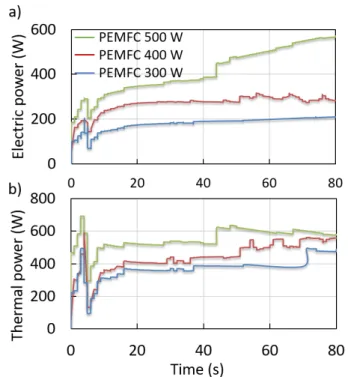
Fig. 10 shows the electrical and thermal power trends. The thermal power has been calculated based on (9) and (10). According to Fig. 10a, from 0 to almost 6 s, the electrical power has a sharp rise followed by a drop. It then gradually increases through time for each PEMFC. The intensity of this increase is different in each PEMFC as they have different degradation levels. Fig. 10b illustrates that the thermal power has also experienced a similar trend to the electrical power as they both depend on the drawn current from the stack. In fact, the produced heat, during the first seconds, raises the PEMFC temperature which improves the PEMFC performance and therefore allows the algorithm to gradually increases the PEMFC current.
9
Fig. 10. Evolution of electrical power (a) and thermal power (b) of the three PEMFCs during an adaptive cold start from -20°C
Table II presents the required current to reach the maximum power and the corresponding thermal power of each utilized PEMFC stack at two different temperatures. An important point that needs to be underlined here is the influence of temperature variation and PEMFC degradation on the maximum power point values. According to this table, the 500-W PEMFC reaches higher current levels than the other ones during cold startup. The PEMFC current level, which significantly changes during the cold start process, directly reflects the rate of water and heat production inside the stack. Table II also indicates that the 500-W PEMFC produces more heat compared to other two PEMFCs during the cold start which makes this PEMFC faster in terms of reaching the temperature level of 0 ℃. Therefore, this analysis justifies the rapid temperature rise of the 500-W PEMFC from -20°C to 0°C in 43 s, compared to 51 s for the 400-W PEMFC and 68 s for the 300-W PEMFC as shown in Fig. 11. From Fig. 11, the effect of degradation on the performance of the proposed strategy can be realized. The degradation of the PEMFC causes a rise on heating time because the maximum power as well as the produced thermal power decrease when the PEMFC is degraded. The heating time and the PEMFC power are different for the three PEMFCs during cold start, which affects the energy consumption. It is important to note that the consumed energy for the purge procedure is included in the presented energy consumption of the adaptive cold start strategy in Fig. 11. The experimental validation of the proposed strategy was repeated 20 times for each PEMFC with a standard deviation of 5s regarding the heating time and 54 J cm-2 concerning the energy consumption.
TABLE II
CURRENT CORRESPONDING TO MAXIMUM POWER (IPMAX),
MAXIMUM POWER (PMAX) AND THERMAL POWER DURING THE
ADAPTIVE COLD STARTUP
PEMFC Temperature IPmax Pmax Thermal
power 300 W -15℃ 13.5 A 180 W 358 W 3℃ 14.31 A 196 W 387 W 400 W -15℃ 17 A 275 W 400 W 3 ℃ 20 A 305 W 493 W 500 W -15℃ 21 A 340 W 533 W 3℃ 28.3 A 561 W 579 W
Fig. 11. Heating time and energy consumption of the three PEMFCs during the adaptive cold startup from -20°C
Fig. 12 compares the performance of the adaptive strategy in different initial temperatures. According to this figure, the duration to achieve the melting point as well as the consumed energy changes almost linearly with the start-up temperature.
Fig. 12. Cold startup performance of the 400-W PEMFC for different initial temperatures
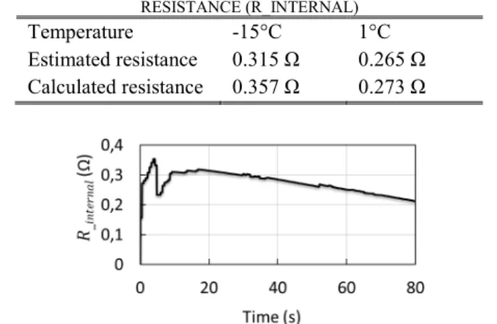
To confirm the accuracy of the online parameter identification process, the physical relevance of the estimated PEMFC resistance is studied for the 400-W PEMFC. Table III compares the estimated and the calculated membrane resistance at two different temperatures. The estimated membrane resistance (𝑅𝑅𝑖𝑖𝑛𝑛𝑁𝑁𝑐𝑐𝑎𝑎𝑛𝑛𝑎𝑎𝑐𝑐) by the Amphlett model depends on the
current, temperature, and the three empirical parameters (𝑅𝑅𝑖𝑖𝑛𝑛𝑁𝑁𝑐𝑐𝑎𝑎𝑛𝑛𝑎𝑎𝑐𝑐 = µ1 + µ2 Tfc + µ3 ifc). The calculated membrane
resistance is deducted from the slope of the linear region of the measured polarization curve at the given temperature. This
10 slope is approximately equal to the PEMFC internal resistance. From Table III, the calculated values of 𝑅𝑅𝑖𝑖𝑛𝑛𝑁𝑁𝑐𝑐𝑎𝑎𝑛𝑛𝑎𝑎𝑐𝑐 are in
agreement with the estimated values. Fig. 13 also shows the evolution of the estimated resistance by the online PEMFC model for the 400-W PEMFC. As is seen in this figure, 𝑅𝑅𝑖𝑖𝑛𝑛𝑁𝑁𝑐𝑐𝑎𝑎𝑛𝑛𝑎𝑎𝑐𝑐 gradually decreases during the cold startup process.
This is due to the fact that 𝑅𝑅𝑖𝑖𝑛𝑛𝑁𝑁𝑐𝑐𝑎𝑎𝑛𝑛𝑎𝑎𝑐𝑐 is dependent on the stack
temperature, and therefore, the rise of temperature results in the hydration of the membrane.
TABLE III
THE ESTIMATED AND CALCULATED VALUE OF THE MEMBRANE RESISTANCE (R_INTERNAL)
Temperature -15°C 1°C
Estimated resistance 0.315 Ω 0.265 Ω Calculated resistance 0.357 Ω 0.273 Ω
Fig. 13. Evolution of the estimated resistance of the Amphlett model during an adaptive cold startup test with the 400-W PEMFC from -20°C
V. CONCLUSION
This paper presents an adaptive cold startup strategy for a PEMFC based on the prediction of the PEMFC maximum power point during the cold startup. The core of this strategy is a purge procedure before shutdown and a PEMFC maximum power point tracking algorithm. The maximum power point is identified using an online PEMFC model composed of a multi-input semi-empirical model and a Kalman filter. From the predicted power curve, the current corresponding to the maximum power is extracted and imposed to the PEMFC during the cold start. The proposed strategy is experimentally validated by using three 500-W PEMFCs with different degradation levels. In order to improve the performance of the cold startup strategy, a parametric study is also performed to tune the operating parameters of the PEMFC (fan speed, anode pressure, purge and micro short-circuit) for the cold startup test. The conducted parametric study reveals that the fan speed must be set to the minimum level to keep the produced heat inside the stack. Moreover, it shows that higher anode pressure is favorable as it decreases the heating time. Regarding the purge procedure after shutdown, it is confirmed that it is effective in improving cold start performance. However, the PEMFC short circuit during cold start shows a negative impact on the cold start performance and should be deactivated.
The experimental results show that the proposed adaptive strategy is perfectly functional for a cold startup from -20°C. It is capable of coping with the PEMFC parameters variation during cold startup and keeps the current density at high levels, resulting in the PEMFC performance improvement caused by membrane hydration and temperature increase. The adaptive strategy is economical in terms of energy consumption because
it avoids external heating by maximizing the PEMFC internal heat and avoiding operating the PEMFC at low voltage levels. The outcomes of this paper put forward the following directions for future studies:
• The proposed adaptive strategy has been experimentally validated for three 500-W PEMFCs. The latest DOE target for the cold startup of the FCHEV is an 80-kW PEMFC at -20 in less than 30s and less than 5 MJ of energy. Therefore, the adaptive strategy of this work should be scaled up in future. • The impact of the suggested adaptive strategy on the
PEMFC lifetime should be studied.
• The operating temperature of the proposed strategy is limited to -20°C. For lower operating temperatures, more focus should be given to the development of an online ice estimation algorithm combined with a hybrid cold start solution. This algorithm should be based on an adaptive maximum cold start mode, as the main cold start solution, and an external heating method used when cathode catalyst layer is blocked by ice.
• In this article, an open-cathode PEMFC is used because it benefits from a simpler and faster experimental implementation. Unlike the typical liquid-cooled automotive PEM fuel cells, an open-cathode PEMFC system requires no compressor, humidifier, hydrogen recirculation pump or water coolant loop, which dramatically simplifies system design. Therefore, more concrete studies are required in future to focus on experimental performance evaluation of the proposed strategy in sub-freezing conditions with a water-cooled PEMFC.
ACKNOWLEDGEMENTS
This work was supported in part by the Bureau de l’éfficacité et de l’innovation énergétique, Ministère des Ressources Naturelles et de la Faune du Québec, the Natural Sciences and Engineering Research Council of Canada (NSERC), the Fonds de recherche du Québec–Nature et technologies (FRQNT), and Canada Research Chairs program.
REFERENCES
[1] C. Dépature, W. Lhomme, P. Sicard, A. Bouscayrol, and L. Boulon, "Real-Time Backstepping Control for Fuel Cell Vehicle Using Supercapacitors," IEEE Transactions on Vehicular Technology, vol. 67, no. 1, pp. 306-314, 2018, doi: 10.1109/TVT.2017.2728823. [2] C. C. Chan, A. Bouscayrol, and K. Chen, "Electric, Hybrid, and
Fuel-Cell Vehicles: Architectures and Modeling," IEEE
Transactions on Vehicular Technology, vol. 59, no. 2, pp. 589-598,
2010, doi: 10.1109/TVT.2009.2033605.
[3] A. M. Ali, A. Ghanbar, and D. Söffker, "Optimal Control of Multi-Source Electric Vehicles in Real Time Using Advisory Dynamic Programming," IEEE Transactions on Vehicular Technology, vol. 68, no. 11, pp. 10394-10405, 2019, doi: 10.1109/TVT.2019.2941523.
[4] X. Lü, Y. Qu, Y. Wang, C. Qin, and G. Liu, "A comprehensive review on hybrid power system for PEMFC-HEV: Issues and strategies," Energy Conversion and Management, vol. 171, pp. 1273-1291, 2018/09/01/ 2018, doi: https://doi.org/10.1016/j.enconman.2018.06.065.
11
[5] B. Geng, J. K. Mills, and D. Sun, "Two-Stage Energy Management Control of Fuel Cell Plug-In Hybrid Electric Vehicles Considering Fuel Cell Longevity," IEEE Transactions on Vehicular Technology, vol. 61, no. 2, pp. 498-508, 2012, doi: 10.1109/TVT.2011.2177483. [6] S. Ziaeinejad, Y. Sangsefidi, and A. Mehrizi-Sani, "Fuel Cell-Based Auxiliary Power Unit: EMS, Sizing, and Current Estimator-Based Controller," IEEE Transactions on Vehicular Technology, vol. 65, no. 6, pp. 4826-4835, 2016, doi: 10.1109/TVT.2016.2552722. [7] W. Schmittinger and A. Vahidi, "A review of the main parameters
influencing long-term performance and durability of PEM fuel cells," Journal of Power Sources, vol. 180, no. 1, pp. 1-14, 5/15/ 2008, doi: http://dx.doi.org/10.1016/j.jpowsour.2008.01.070. [8] C. Depature, A. Bouscayrol, and L. Boulon, "Range-Extender
Electric Vehicle Using a Fuel Cell," in 2013 IEEE Vehicle Power
and Propulsion Conference (VPPC), 15-18 Oct. 2013 2013, pp.
1-6, doi: 10.1109/VPPC.2013.6671702.
[9] Y. Luo and K. Jiao, "Cold start of proton exchange membrane fuel cell," Progress in Energy and Combustion Science, vol. 64, pp. 29-61, 2018, doi: 10.1016/j.pecs.2017.10.003.
[10] Z. Wan, H. Chang, S. Shu, Y. Wang, and H. Tang, "A review on cold start of proton exchange membrane fuel cells," Energies, vol. 7, no. 5, pp. 3179-3203, 2014, doi: 10.3390/en7053179.
[11] H. Meng and B. Ruan, "Numerical studies of cold‐start phenomena in PEM fuel cells: A review," International Journal of Energy
Research, vol. 35, no. 1, pp. 2-14, 2011.
[12] (2016). Multi-Year Research, Development, and Demonstration
Plan. [Online] Available:
https://energy.gov/eere/fuelcells/downloads/fuel-cell-technologies-office-multi-year-research-development-and-22
[13] Y. Luo, Q. Guo, Q. Du, Y. Yin, and K. Jiao, "Analysis of cold start processes in proton exchange membrane fuel cell stacks," Journal
of Power Sources, vol. 224, pp. 99-114, 2013, doi:
10.1016/j.jpowsour.2012.09.089.
[14] A. Amamou, L. Boulon, S. Kelouwani, K. Agbossou, and P. Sicard, "Thermal Management Strategies for Cold Start of Automotive PEMFC," presented at the Vehicle Power and Propulsion Conference (VPPC), 2015 IEEE, Montreal, 2015.
[15] W. S. Wheat, M. A. Meltser, and D. A. Masten, "Fuel cell energy management system for cold environments System for cold environment," US Patent 6,727,013 B2, 2004. [Online]. Available: https://www.google.ca/patents/US6727013
[16] B. J. Clingerman et al., "Fuel cell system water management strategy for freeze capability," US Patent 2007/0298289 A1, 2007.
[Online]. Available: https://www.google.ca/patents/US20070298289
[17] A. A. Pesaran et al., PEM fuel cell freeze and rapid startup
investigation. Golden, Colo.: National Renewable Energy
Laboratory (in English), 2005.
[18] R. J. Assarabowski, W. T. Unkert, L. A. Bach, A. P. Grasso, and B. C. Olsommer, "Method and apparatus for preventing water in fuel cell power plants from freezing during storage," US Patent 6,797,421 B2, 2004. [Online]. Available: https://www.google.com/patents/US6797421
[19] M. Khandelwal, S. Lee, and M. M. Mench, "One-dimensional thermal model of cold-start in a polymer electrolyte fuel cell stack,"
Journal of Power Sources, vol. 172, no. 2, pp. 816-830, 10/25/ 2007,
doi: http://dx.doi.org/10.1016/j.jpowsour.2007.05.028.
[20] Y. Zhou, Y. Luo, S. Yu, and K. Jiao, "Modeling of cold start processes and performance optimization for proton exchange membrane fuel cell stacks," Journal of Power Sources, vol. 247, pp. 738-748, 2014, doi: 10.1016/j.jpowsour.2013.09.023.
[21] L. Youcai, X. Sichuan, Y. Zhigang, and L. Youcai, "Experiment and simulation study on cold start of automotive PEMFC," in
Electric Information and Control Engineering (ICEICE), 2011 International Conference on, 15-17 April 2011 2011, pp.
2166-2170, doi: 10.1109/ICEICE.2011.5776891.
[22] N. Henao, S. Kelouwani, K. Agbossou, and Y. Dubé, "Proton exchange membrane fuel cells cold startup global strategy for fuel cell plug-in hybrid electric vehicle," Journal of Power Sources, vol. 220, no. 0, pp. 31-41, 12/15/ 2012, doi: http://dx.doi.org/10.1016/j.jpowsour.2012.07.088.
[23] K. Jiao, I. E. Alaefour, G. Karimi, and X. Li, "Simultaneous measurement of current and temperature distributions in a proton exchange membrane fuel cell during cold start processes,"
Electrochimica Acta, vol. 56, no. 8, pp. 2967-2982, 3/1/ 2011, doi:
http://dx.doi.org/10.1016/j.electacta.2011.01.019.
[24] F. Jiang and C.-Y. Wang, "Potentiostatic start-up of PEMFCs from subzero temperatures," Journal of the Electrochemical Society, vol. 155, no. 7, pp. B743-B751, 2008 2008, doi: 10.1149/1.2927381. [25] R. Lin, Y. Weng, X. Lin, and F. Xiong, "Rapid cold start of proton
exchange membrane fuel cells by the printed circuit board technology," International Journal of Hydrogen Energy, vol. 39, no. 32, pp. 18369-18378, 10/31/ 2014, doi: http://dx.doi.org/10.1016/j.ijhydene.2014.09.065.
[26] Q. Guo, Y. Luo, and K. Jiao, "Modeling of assisted cold start processes with anode catalytic hydrogen-oxygen reaction in proton exchange membrane fuel cell," International Journal of Hydrogen
Energy, vol. 38, no. 2, pp. 1004-1015, 2013, doi:
10.1016/j.ijhydene.2012.10.067.
[27] R. Lin, Y. Weng, Y. Li, X. Lin, S. Xu, and J. Ma, "Internal behavior of segmented fuel cell during cold start," International Journal of
Hydrogen Energy, vol. 39, no. 28, pp. 16025-16035, 9/23/ 2014, doi:
http://dx.doi.org/10.1016/j.ijhydene.2013.12.083.
[28] R. K. Ahluwalia and X. Wang, "Rapid self-start of polymer electrolyte fuel cell stacks from subfreezing temperatures," Journal
of Power Sources, vol. 162, no. 1, pp. 502-512, 11/8/ 2006, doi:
http://dx.doi.org/10.1016/j.jpowsour.2006.06.071.
[29] F. Jiang, C. Y. Wang, and K. S. Chen, "Current ramping: A strategy for rapid start-up of PEMFCs from subfreezing environment,"
Journal of the Electrochemical Society, vol. 157, no. 3, pp.
B342-B347, 2010, doi: 10.1149/1.3274820.
[30] Y. Hishinuma, T. Chikahisa, F. Kagami, and T. Ogawa, "The design and performance of a PEFC at a temperature below freezing," JSME
International Journal Series B Fluids and Thermal Engineering,
vol. 47, no. 2, pp. 235-241, 2004.
[31] H. Meng, "Numerical studies of cold-start phenomenon in PEM fuel cells," Electrochimica Acta, vol. 53, no. 22, pp. 6521-6529, 9/20/ 2008, doi: http://dx.doi.org/10.1016/j.electacta.2008.04.044. [32] G. Gwak and H. Ju, "A rapid start-up strategy for polymer
electrolyte fuel cells at subzero temperatures based on control of the operating current density," International Journal of Hydrogen
Energy, vol. 40, no. 35, pp. 11989-11997, 9/21/ 2015, doi:
http://dx.doi.org/10.1016/j.ijhydene.2015.05.179.
[33] A. A. Amamou, S. Kelouwani, L. Boulon, and K. Agbossou, "A Comprehensive Review of Solutions and Strategies for Cold Start of Automotive Proton Exchange Membrane Fuel Cells," IEEE
Access, vol. 4, pp. 4989-5002, 2016, doi:
10.1109/ACCESS.2016.2597058.
[34] P. Liu and S. Xu, "A Progress Review on Heating Methods and Influence Factors of Cold Start for Automotive PEMFC System," 2020. [Online]. Available: https://doi.org/10.4271/2020-01-0852. [35] S. Curtin and J. Gangi, "Fuel Cell Technologies Market Report,"
U.S. Department Of ENERGY, 2017.
[36] A. Amamou, L. Boulon, and S.Kelouwani, "Comparison of self cold start strategies of automotive Proton Exchange Membrane Fuel Cell," presented at the International Conference on Industrial Technology, Lyon, France, 2018.
[37] Q. Du, B. Jia, Y. Luo, J. Chen, Y. Zhou, and K. Jiao, "Maximum power cold start mode of proton exchange membrane fuel cell,"
International Journal of Hydrogen Energy, vol. 39, no. 16, pp.
8390-8400, 2014, doi: 10.1016/j.ijhydene.2014.03.056.
[38] M. Ibrahim, N. Y. Steiner, S. Jemei, and D. Hissel, "Wavelet-Based Approach for Online Fuel Cell Remaining Useful Lifetime Prediction," IEEE Transactions on Industrial Electronics, vol. 63, no. 8, pp. 5057-5068, 2016, doi: 10.1109/TIE.2016.2547358. [39] D. Zhong et al., "Low temperature durability and consistency
analysis of proton exchange membrane fuel cell stack based on comprehensive characterizations," Applied Energy, vol. 264, p. 114626, 2020.
[40] D. Zhou, A. Al-Durra, I. Matraji, A. Ravey, and F. Gao, "Online Energy Management Strategy of Fuel Cell Hybrid Electric Vehicles: A Fractional-Order Extremum Seeking Method," IEEE
Transactions on Industrial Electronics, vol. 65, no. 8, pp.
6787-6799, 2018, doi: 10.1109/TIE.2018.2803723.
[41] N. Bizon, "Energy optimization of fuel cell system by using global extremum seeking algorithm," Applied Energy, vol. 206, pp.
458-474, 2017/11/15/ 2017, doi: https://doi.org/10.1016/j.apenergy.2017.08.097.
12
[42] K. Ettihir, L. Boulon, M. Becherif, K. Agbossou, and H. S.
Ramadan, "Online identification of semi-empirical model parameters for PEMFCs," International Journal of Hydrogen
Energy, vol. 39, no. 36, pp. 21165-21176, 2014/12/12/ 2014, doi:
https://doi.org/10.1016/j.ijhydene.2014.10.045.
[43] T. Wang et al., "An optimized energy management strategy for fuel cell hybrid power system based on maximum efficiency range identification," Journal of Power Sources, vol. 445, p. 227333,
2020/01/01/ 2020, doi: https://doi.org/10.1016/j.jpowsour.2019.227333.
[44] A. Amamou, M. Kandidayeni, L. Boulon, and S. Kelouwani, " Real time adaptive efficient cold start strategy for proton exchange membrane fuel cells," Applied Energy, vol. 216, pp. 21-30,
2018/04/15 2018, doi: https://doi.org/10.1016/j.apenergy.2018.02.071.
[45] M. Kandidayeni, A. Macias, A. A. Amamou, L. Boulon, S.
Kelouwani, and H. Chaoui, "Overview and benchmark analysis of fuel cell parameters estimation for energy management purposes,"
Journal of Power Sources, vol. 380, pp. 92-104, 2018/03/15/ 2018,
doi: https://doi.org/10.1016/j.jpowsour.2018.01.075.
[46] S. Strahl, A. Husar, and J. Riera, "Experimental study of hydrogen purge effects on performance and efficiency of an open-cathode Proton Exchange Membrane fuel cell system," Journal of Power
Sources, vol. 248, pp. 474-482, 2014/02/15/ 2014, doi:
https://doi.org/10.1016/j.jpowsour.2013.09.122.
[47] R. K. Ahluwalia and X. Wang, "Buildup of nitrogen in direct hydrogen polymer-electrolyte fuel cell stacks," Journal of Power
Sources, vol. 171, no. 1, pp. 63-71, 2007/09/19/ 2007, doi:
https://doi.org/10.1016/j.jpowsour.2007.01.032.
[48] S. Strahl, A. Husar, and M. Serra, "Development and experimental validation of a dynamic thermal and water distribution model of an open cathode proton exchange membrane fuel cell," Journal of
Power Sources, vol. 196, no. 9, pp. 4251-4263, 2011/05/01/ 2011,
doi: https://doi.org/10.1016/j.jpowsour.2010.10.074.
[49] M. Kandidayeni, A. M. F, L. Boulon, and S. Kelouwani, "Efficiency Enhancement of an Open Cathode Fuel Cell Through a Systemic Management," IEEE Transactions on Vehicular Technology, vol. 68, no. 12, pp. 11462-11472, 2019, doi: 10.1109/TVT.2019.2944996.
[50] S. Strahl, A. Husar, P. Puleston, and J. Riera, "Performance Improvement by Temperature Control of an Open-Cathode PEM Fuel Cell System," Fuel Cells, vol. 14, no. 3, pp. 466-478, 2014, doi: 10.1002/fuce.201300211.
[51] Q. Meyer et al., "Optimisation of air cooled, open-cathode fuel cells: Current of lowest resistance and electro-thermal performance mapping," Journal of Power Sources, vol. 291, pp. 261-269,
2015/09/30/ 2015, doi: https://doi.org/10.1016/j.jpowsour.2015.04.101.
[52] Y. Wang, P. P. Mukherjee, J. Mishler, R. Mukundan, and R. L. Borup, "Cold start of polymer electrolyte fuel cells: Three-stage startup characterization," Electrochimica Acta, vol. 55, no. 8, pp.
2636-2644, 3/1/ 2010, doi: http://dx.doi.org/10.1016/j.electacta.2009.12.029.
[53] R. H. Barton, T. D. Uong, C. J. Schembri, and G. A. Skinner, "Fuel cell purging method and apparatus," ed: Google Patents, 2005. [54] V. Mishra, F. Yang, and R. Pitchumani, "Analysis and design of
PEM fuel cells," Journal of Power Sources, vol. 141, no. 1, pp.
47-64, 2005/02/16/ 2005, doi: https://doi.org/10.1016/j.jpowsour.2004.08.051.
[55] H. Penas. "Créer un plan d’expérience : méthode rapide et efficace (sans ANOVA)." http://3dc.asso-web.com/actualite-12-creer-un-plan-d-experience-methode-rapide-et-efficace-sans-anova.html (accessed 21-12, 1017).
[56] J. Roberts, J. St-Pierre, M. van der Geest, A. Atbi, and N. Fletcher, "Methods for improving the cold starting capability of an electrochemical fuel cell," ed: Google Patents, 2003.
[57] C.-Y. Lee, Y.-M. Lee, and S.-J. Lee, "Local area water removal analysis of a proton exchange membrane fuel cell under gas purge conditions," (in eng), Sensors (Basel), vol. 12, no. 1, pp. 768-783, 2012, doi: 10.3390/s120100768.
[58] P. Xu and S. Xu, "A Progress Review on Gas Purge for Enhancing Cold Start Performance in PEM Fuel Cell," 2018. [Online]. Available: https://doi.org/10.4271/2018-01-1312.
[59] E. Thompson and R. Fuss, "Control system and method for starting a frozen fuel cell," ed: Google Patents, 2004.
[60] H. Y. Tang, A. D. Santamaria, J. Bachman, and J. W. Park,
"Vacuum-assisted drying of polymer electrolyte membrane fuel cell," Applied Energy, vol. 107, pp. 264-270, 2013, doi: 10.1016/j.apenergy.2013.01.053.
[61] K. Tajiri, C.-Y. Wang, and Y. Tabuchi, "Water removal from a PEFC during gas purge," Electrochimica Acta, vol. 53, no. 22, pp.
6337-6343, 9/20/ 2008, doi: http://dx.doi.org/10.1016/j.electacta.2008.04.035.
[62] K. Tajiri, Y. Tabuchi, F. Kagami, S. Takahashi, K. Yoshizawa, and C.-Y. Wang, "Effects of operating and design parameters on PEFC cold start," Journal of Power Sources, vol. 165, no. 1, pp. 279-286, 2/25/ 2007, doi: http://dx.doi.org/10.1016/j.jpowsour.2006.12.017.
[63] A. K. Al-Othman, N. A. Ahmed, F. S. Al-Fares, and M. E.
AlSharidah, "Parameter Identification of PEM Fuel Cell Using Quantum-Based Optimization Method," Arabian Journal for
Science and Engineering, journal article vol. 40, no. 9, pp.
2619-2628, September 01 2015, doi: 10.1007/s13369-015-1711-0. [64] F. Peng, L. Ren, Y. Zhao, and L. Li, "Hybrid dynamic
modeling-based membrane hydration analysis for the commercial high-power integrated PEMFC systems considering water transport equivalent,"
Energy Conversion and Management, vol. 205, p. 112385,
2020/02/01/ 2020, doi: https://doi.org/10.1016/j.enconman.2019.112385.
[65] M. Kandidayeni, A. O. M. Fernandez, A. Khalatbarisoltani, L. Boulon, S. Kelouwani, and H. Chaoui, "An Online Energy Management Strategy for a Fuel Cell/Battery Vehicle Considering the Driving Pattern and Performance Drift Impacts," IEEE
Transactions on Vehicular Technology, vol. 68, no. 12, pp.
11427-11438, 2019, doi: 10.1109/TVT.2019.2936713.
[66] J. Jaguemont, L. Boulon, P. Venet, Y. Dubé, and A. Sari, "Lithium-Ion Battery Aging Experiments at Subzero Temperatures and Model Development for Capacity Fade Estimation," IEEE Transactions on
Vehicular Technology, vol. 65, no. 6, pp. 4328-4343, 2016, doi:
10.1109/TVT.2015.2473841.
[67] M. Yue, S. Jemei, and N. Zerhouni, "Health-Conscious Energy Management for Fuel Cell Hybrid Electric Vehicles Based on Prognostics-Enabled Decision-Making," IEEE Transactions on
Vehicular Technology, vol. 68, no. 12, pp. 11483-11491, 2019, doi:
10.1109/TVT.2019.2937130.
[68] H. Haas, S. Chor, L. I. Cosacescu, R. Rahmani, and C. Richards, "Systems and methods for fuel cell shutdown," ed: Google Patents, 2006.
[69] S. Ge and C.-Y. Wang, "Characteristics of subzero startup and water/ice formation on the catalyst layer in a polymer electrolyte fuel cell," Electrochimica Acta, vol. 52, no. 14, pp. 4825-4835, 4/1/ 2007, doi: http://dx.doi.org/10.1016/j.electacta.2007.01.038. [70] S. Ge and C.-Y. Wang, "In situ imaging of liquid water and ice
formation in an operating PEFC during cold start," Electrochemical
and Solid-State Letters, vol. 9, no. 11, pp. A499-A503, 2006.
[71] K. Tajiri and C.-Y. Wang, "Cold Start of Polymer Electrolyte Fuel Cells," in Modeling and Diagnostics of Polymer Electrolyte Fuel
Cells: Springer, 2010, pp. 89-128.
[72] R. L. Borup, J. R. Davey, F. H. Garzon, D. L. Wood, P. M. Welch, and K. More, "PEM fuel cell durability with transportation transient operation," in ECS Transactions, 2006, vol. 3, 1 ed., pp. 879-886, doi: 10.1149/1.2356206. [Online]. Available:
http://www.scopus.com/inward/record.url?eid=2-s2.0-33846992585&partnerID=40&md5=363c68ef1fd3a493c438bb2d8 96c1d35
[73] P. K. Sinha and C.-Y. Wang, "Gas purge in a polymer electrolyte fuel cell," Journal of The Electrochemical Society, vol. 154, no. 11, pp. B1158-B1166, 2007.
[74] J. C. Amphlett, R. F. Mann, B. A. Peppley, P. R. Roberge, and A. Rodrigues, "A model predicting transient responses of proton exchange membrane fuel cells," Journal of Power Sources, vol. 61, no. 1, pp. 183-188, 1996/07/01/ 1996, doi: http://dx.doi.org/10.1016/S0378-7753(96)02360-9.
[75] Q. Li, T. Wang, C. Dai, W. Chen, and L. Ma, "Power Management Strategy Based on Adaptive Droop Control for a Fuel Cell-Battery-Supercapacitor Hybrid Tramway," IEEE Transactions on Vehicular
Technology, vol. 67, no. 7, pp. 5658-5670, 2018, doi:
10.1109/TVT.2017.2715178.
[76] A. M. Fernandez, M. Kandidayeni, L. Boulon, and H. Chaoui, "An Adaptive State Machine Based Energy Management Strategy for a Multi-Stack Fuel Cell Hybrid Electric Vehicle," IEEE Transactions