HAL Id: tel-02569080
https://hal.archives-ouvertes.fr/tel-02569080
Submitted on 11 May 2020HAL is a multi-disciplinary open access archive for the deposit and dissemination of sci-entific research documents, whether they are pub-lished or not. The documents may come from teaching and research institutions in France or abroad, or from public or private research centers.
L’archive ouverte pluridisciplinaire HAL, est destinée au dépôt et à la diffusion de documents scientifiques de niveau recherche, publiés ou non, émanant des établissements d’enseignement et de recherche français ou étrangers, des laboratoires publics ou privés.
Performance Analysis under Correlated Fading
Conditions
Guowei Yang
To cite this version:
Guowei Yang. Space-Diversity Free-Space Optical Systems: Performance Analysis under Correlated Fading Conditions. Signal and Image processing. Ecole Centrale Marseille (ECM), 2013. English. �tel-02569080�
ÉCOLE CENTRALE MARSEILLE
N◦attribué par la bibliothèque XXXX
TITRE:
Systèmes de Communication Optique Aérienne Utilisant la Diversité
Spatiale: Analyse de Performances en Considérant des
Évanouissements Corrélés
THÈSE
pour obtenir le grade de DOCTEUR
délivré par L’ÉCOLE CENTRALE MARSEILLE
École Doctorale : Physique et Sciences de la Matière Mention : Optique, Photonique et Traitement d’Image
Effectuée à l’INSTITUT FRESNEL Présentée et soutenue publiquement par:
Guowei YANG le 20 Septembre 2013
Directeur de thèse: Mr. Salah BOURENNANE Co-encadrant de thèse: Mr. Mohammad-Ali KHALIGHI
JURY :
Mr. Zabih GHASSEMLOOY Université Northumbria, R.U. Président du jury
Mr. Alain SIBILLE Télécom ParisTech Rapporteur
Mme Anne JULIEN-VERGONJANNE ENSIL, Limoges Rapporteur Mr. Hassan AKHOUAYRI École Centrale Marseille Examinateur Mr. Salah BOURENNANE École Centrale Marseille Directeur de thèse Mr. Mohammad-Ali KHALIGHI École Centrale Marseille Co-encadrant de thèse
ÉCOLE CENTRALE MARSEILLE
No. assigned by library XXXX
TITLE:
Space-Diversity Free-Space Optical Systems:
Performance Analysis under Correlated Fading Conditions
THESIS
to obtain the degree of Doctor of Science
issued by ÉCOLE CENTRALE MARSEILLE
Doctoral school : Physics and Material Sciences Discipline : Optics, Photonics and Image Processing
Accomplished at INSTITUT FRESNEL Presented and defended publicly by:
Guowei YANG on September 20th 2013
Thesis advisor: Prof. Salah BOURENNANE Thesis co-advisor: Dr. Mohammad-Ali KHALIGHI
COMMITTEE :
Prof. Zabih GHASSEMLOOY Northumbria University, U.K. Chair
Prof. Alain SIBILLE Télécom ParisTech Reviewer
Prof. Anne JULIEN-VERGONJANNE ENSIL, Limoges Reviewer Prof. Hassan AKHOUAYRI École Centrale Marseille Examiner Prof. Salah BOURENNANE École Centrale Marseille Thesis advisor Dr. Mohammad-Ali KHALIGHI École Centrale Marseille Thesis co-advisor
v
Acknowledgments
The work presented in this thesis was mainly carried out in GSM (Groupe Signaux Multidimen-sionnels) group of Institut Fresnel. I would like to express my sincere gratitude to the China Schol-arship Council and École Centrale Marseille, who offered me the opportunity to carry out the re-search here. I also would like to acknowledge Opticwise COST Action IC1101 for providing me the financial support to visit the lab of OCRG (Optical Communications Research Group) at Northum-bria University, and carry out some experimental work on this research.
I wish here to express sincere thanks to my supervisors Dr.Mohammad-Ali Khalighi and Prof. Salah Bourennane for their continuous guidance, support and encouragement throughout my PhD study. Without their constructive advice and reading the material without delay including this thesis, it would have been impossible to finish my research work on time. Also, Mr. Khalighi offer me lots of help on my living in France. In particular, during my visit at Northumbria Uni-versity, I would like to thank immensely Prof. Zabih Ghassemlooy and Dr. Sujan Rajbhandari for providing invaluable help and advice throughout the experimental work carried out in their lab. Sincere thanks also go to Dr. Dehao Wu for his information and help on the living in UK.
I would like to express my highly appreciation to the reviewers, Prof. Anne Julien-Vergonjanne and Alain Sibille, for their detailed and constructive review on my work. I wish also to thank Prof. Hassan Akhouayri and Zabih Ghassemlooy for their participation in the jury and careful examina-tion of my manuscript.
My special thanks go to the members of the GSM group, who shared many with me in the past three years. Thanks to the researchers Dr.Mouloud Adel, Dr. Julien Marot, and Dr. Caroline Fos-sati, and Dr. Stephane Derrode for their support of my work. I also wish to thank my other lab col-leagues, including Fang Xu, Dong Han, Haiping Jiang, Yi Yin, Riad Khelifi, Sylvain Jay, Xuefeng Liu, Alexis Cailly, Yi Zhang, Chadi Gabriel, Tao Lin, Zhiyong Xiao, Nabil Boughnim, Valerian Nemesin, et al., for providing excellent research environment and also for making time really enjoyable.
I am deeply grateful to my family, especially my wife - Bixia, for their constant support and encouragement during my stay at Institut Fresnel. Finally, I would like to acknowledge the greatest joy I enjoy from seeing the growth of my little son - Lele.
Table of contents
List of Notations 1
List of Acronyms 3
Résumé étendu 7
1 General Introduction 11
1.1 Free-space optics overview . . . 11
1.1.1 Brief history . . . 11
1.1.2 Advantages and applications of FSO . . . 13
1.1.3 Challenges of FSO . . . 15
1.2 Thesis objectives . . . 15
1.3 Thesis overview and contributions . . . 16
1.3.1 Thesis outline . . . 16
1.3.2 Author’s contributions . . . 18
1.3.3 Author’s publications . . . 18
2 Fundamentals of FSO Communication 21 2.1 Introduction . . . 21 2.2 Transmitter . . . 22 2.2.1 Signal modulation . . . 23 2.2.2 Optical source . . . 23 2.3 Atmospheric channel . . . 24 2.3.1 Atmospheric attenuation . . . 24 2.3.2 Turbulence-induced fading . . . 25 2.3.3 Link margin . . . 25
2.4 Receiver . . . 26
2.4.1 Photodetector . . . 26
2.4.2 Signal demodulation . . . 27
2.5 Study of turbulence-induced fading . . . 27
2.5.1 Statistical models . . . 28
2.5.2 ΓΓ channel model . . . 28
2.5.3 Wave-optics simulation . . . 30
2.5.4 Experimental study . . . 31
2.6 Methods to mitigate turbulence-induced fading . . . 32
2.7 Channel modeling for space-diversity FSO systems . . . 34
2.8 Chapter summary . . . 35
3 Evaluating Fading Correlation in Space-Diversity FSO Systems 37 3.1 Introduction . . . 37
3.2 Wave-optics simulations . . . 38
3.2.1 Parameter setting for WO simulations . . . 38
3.2.2 Calculating channel fading and correlation coefficients . . . 38
3.3 Study of fading correlation in SIMO case . . . 39
3.3.1 General assumptions . . . 39
3.3.2 Simulation parameters . . . 40
3.3.3 Numerical results and discussions . . . 41
3.4 Remarks on MISO and MIMO cases . . . 43
3.4.1 Fading correlation for MISO FSO system . . . 45
3.4.2 General model for MIMO system . . . 46
3.5 Chapter summary . . . 47
4 Accounting the Effect of Fading Correlation inΓΓ FSO Channels 49 4.1 Introduction . . . 50
4.2 CorrelatedΓΓ RV generation method . . . 50
4.2.1 DecomposingΓΓ RVs into Gamma RVs . . . 50
4.2.2 Generating correlated Gamma RVs . . . 52
4.3 Criteria for setting small- and large-scale fading correlation coefficients . . . 53
TABLE OF CONTENTS ix
4.3.2 Verifying the proposed criteria for SIMO case . . . 54
4.3.3 General criteria for MISO and MIMO cases . . . 57
4.4 Study of BER performance by MC simulations . . . 59
4.4.1 PIN-based receiver . . . 60
4.4.2 APD-based receiver . . . 64
4.4.3 BER comparison of PIN- and APD-based receivers . . . 66
4.5 Chapter summary . . . 69
5 Analytical Performance Evaluation for Transmission over CorrelatedΓΓ Channels 71 5.1 Introduction . . . 71
5.2 α-µ approximation of mulitple ΓΓ RVs and its applications . . . . 72
5.2.1 α-µ approximation method . . . . 72
5.2.2 Numerical results: goodness-of-fit test and BER performance . . . 75
5.3 Performance analysis based on Padé approximation . . . 82
5.3.1 MGF of sum ofΓΓ RVs . . . 82
5.3.2 BER performance . . . 83
5.3.3 Numerical results . . . 84
5.4 Chapter summary . . . 84
6 Signaling Schemes for Transmit-Diversity FSO Systems 87 6.1 Introduction . . . 87
6.2 Performance comparison of MISO, SIMO and MIMO systems . . . 88
6.2.1 System model and assumptions . . . 88
6.2.2 Numerical results . . . 88
6.3 Space-time schemes for MIMO systems . . . 89
6.3.1 Overview of ST schemes for MIMO FSO systems . . . 89
6.3.2 Contrasting performance of different ST schemes . . . 90
6.4 Chapter summary . . . 94
7 Experimental Measurements in a Controlled Laboratory Environment 95 7.1 Introduction . . . 95
7.2 Description of experiment setup . . . 96
7.3.1 Measuring turbulence strength . . . 98
7.3.2 Study of receiver performance . . . 99
7.4 Effects of aperture averaging and receive-diversity . . . 100
7.5 Fading distribution and correlation coefficient . . . 101
7.6 Chapter summary . . . 103
8 Conclusions and Perspectives 105 8.1 Conclusions . . . 105
8.2 Perspectives . . . 107
A Wave-Optics Simulation of Beam Propagation through Atmosphere 109 A.1 Split-step beam propagation method . . . 109
A.2 Multiple phase screens . . . 110
B Methods to Generate Correlated Gamma RVs 113 B.1 Zhang’s method . . . 113
B.2 Sim’s method . . . 114
C The (m, n)t hJoint Moment of Two CorrelatedΓΓ RVs 117 D The Joint Moments of MultipleΓΓ RVs 119 D.1 MGF of a Gamma vector . . . 119
D.2 The first four joint moments . . . 120
D.3 The nthjoint moment . . . 122
List of Figures 125
List of Tables 129
List of Notations
G APD gain
F0 curvature radius of Gaussian beam’s wavefront
W0 waist size of Gaussian beam
Cn2 refractive-index structure parameter
CT2 temperature structure parameter det(·) matrix determinant
e electron charge
η optical-to-electrical conversion coefficient
kB Boltzmann constant
L0 outer-scale of turbulence
l0 inner-scale of turbulence
λ optical wavelength
f optical frequency
k optical wave number
log(·) natural logarithm
lX lower bound of large-scale turbulence cells
lY upper bound of small-scale turbulence cells
P0 background radiation power
Pe probability of error
ħ Planck constant
Pt transmit power
R post-amplifier transimpedance resistance
ρ0 spatial coherence radius of optical wave
ρc correlation width
ρ fading correlation coefficient
τc channel coherence time
ρX correlation coefficient related to large-scale turbulence
ρY correlation coefficient related to small-scale turbulence
σ2
I scintillation index
σ2
R Rytov variance
Te post-amplifier’s equivalent noise temperature
Tp pulse duration
Ts slot duration
ξ ionization coefficient ratio arg max argument of the maximum
Kυ(·) modified Bessel function of second kind and orderυ Cov(·,·) covariance
erfc(.) complementary error function
〈·〉 ensemble average
E{·} expectation
Γ(·) Gamma function
2F1(·) Gauss hypergeometric function
N (µ,σ2) Gaussian distribution with meanµ and variance σ2 Var(·) variance
List of Acronyms
ΓΓ Gamma-Gamma
AO adaptive optics
APD avalanche photodiode
ARCEP Autorité de Régulation des Communications Électroniques et des Postes AWG arbitrary waveform generator
AWGN additive white Gaussian noise BER bit error rate
CDF cumulative distribution function CHF characteristic function
CSI channel state information DFB distributed-feedback ECC error-correcting coding EGC equal gain combining ESA European Space Agency
FCC Federal Communication Commission
FOV field-of-view
FSO free-space optical Gbps Gigabits per second
GeoLITE Geosynchronous Lightweight Technology Experiment GOLD Global-scale Observations of the Limb and Disk
He-Ne Helium-Neon
IM intensity modulation
IM/DD intensity modulation and direct detection InGaAs Indium Gallium Arsenide
IR infrared
IrDA Infrared Data Association
KS Kolmogorov-Smirnov
LAN local area network LED light-emitting diode
LLR logarithmic likelihood ratio
LoS line-of-sight
LR likelihood ratio
MAP maximum a posteriori Mbps Megabits per second
MC Monte-Carlo
MGF moment generating function MIMO multiple-input multiple-output MISO multiple-input single-output
MLCD Mars Laser Communications Demonstration MLD maximum likelihood detection
MMSE minimum mean-square-error MRC maximal ratio combining MTBF mean time between failures
NASA National Aeronautics and Space Administration NEC Nippon Electric Company
NRZ non-return-to-zero
OAM orbital angular momentum
OCRG Optical Communication Research Group Ofcom Office of Communication
OOK ON-OFFkeying
OSM optical spatial modulation
OSTBC orthogonal space-time block code OWC optical wireless communication P-I optical power versus injection current
PD photodetector
PDF probability density function PIM pulse interval modulation
PIN P-i-N
PMF probability mass function PPM pulse position modulation PSD power spectral density
RC repetition coding
RF radio frequency
RV random variable
SC selection combining
SI scintillation index
SILEX Semiconductor Intersatellite Link Experiment SIMO single-input multiple-output
List of Acronyms 5
SMux spatial multiplexing SNR signal-to-noise ratio
ST space-time
TIA transimpedance amplifier
V-BLAST vertical-Bell laboratories layered space-time VCSEL vertical-cavity surface-emitting laser
VLC visible light communication
WO wave-optics
Résumé étendu
Les communications optiques en espace libre, connues sous le nom de FSO (Free-Space Optics), constituent une solution intéressante pour les transmissions sans-fil point à point à très haut-débit. C’est pour cette raison que cette technologie compte parmi les axes de recherche les plus dynamiques dans le domaine des télécommunications.
Comparée aux communications radio fréquence (RF), les avantages du FSO sont nombreux: tout d’abord, en opérant dans les longueurs d’onde proche de l’infrarouge, on bénéficie d’une bande passante très large, ce qui permet (potentiellement) une transmission de données à très haut débit, allant jusqu’à plusieurs Giga bit par seconde. De plus, le spectre optique utilisé par FSO reste à ce jour non-réglementé et par conséquent aucune licence n’est requise pour effectuer la transmission. D’autre part, FSO établie une liaison point-à-point directionnelle utilisant des faisceaux optiques très focalisés : ceci ce qui rend l’interception du signal par un tiers très difficile. Enfin, les composants utilisés au sein d’un système FSO sont moins coûteux que ceux d’un sys-tème RF. Egalement, comparée aux syssys-tèmes de communication à fibre optique, l’installation d’un système FSO peut être réalisée rapidement, en évitant de lourds et chers travaux de génie civil.
Ces avantages rendent la technologie FSO très propice pour diverses applications. En par-ticulier, FSO est considérée comme solution appropriée au problème du dernier kilomètre, ou “goulot d’étranglement”, limitant le débit des liaisons de communication sur le réseau Internet chez les abonnés. FSO peut également être utilisé dans les réseaux étendus à haut-débit: à savoir la communication entre les bâtiments ou la connectivité de réseaux locaux non co-localisés. Les liaisons FSO peuvent encore être utilisées en tant que liaisons de secours en cas de panne dans les réseaux de fibre optique.
En pratique, malgré tous ces avantages et en raison de la transmission à travers l’atmosphère, les performances d’un système FSO sont essentiellement limitées par des condi-tions météorologiques et atmosphériques. Dans cette thèse, nous nous intéressons aux condicondi-tions d’atmosphère claire, où les turbulences atmosphériques sont la principale source de dégradation des performances des liaisons FSO.
Après avoir établie un bilan historique des communications laser et une introduction aux transmissions FSO dans le Chapitre 1, nous décrivons dans le Chapitre 2 les différentes parties d’une chaîne de transmission FSO, à savoir, l’émetteur, le canal atmosphérique et le récepteur. Concernant l’émetteur, nous expliquons la modulation du signal et les caractéristiques des diodes
laser souvent utilisées. En ce qui concerne le canal atmosphérique, nous expliquons d’abord la perte en propagation due à l’atténuation du faisceau laser dans l’air et aussi à la turbulence atmo-sphérique. La notion de bilan de liaison (link budget) d’un lien FSO sera présentée également. Au niveau du récepteur, nous expliquons le processus de photo-détection et la démodulation du sig-nal. Ensuite, nous nous concentrons sur le problème des turbulences atmosphériques et présen-tons le modèle statistique Gamma-Gamma (ΓΓ ): ce modèle est largement adopté pour décrire les statistiques des fluctuations d’intensité dans les différents régimes de turbulence. Nous abordons également les techniques de réduction de l’effet d’évanouissements du canal (fading) en insistant sur l’approche de diversité spatiale, particulièrement intéressante du point de vue implémenta-tion pratique de ces systèmes. En effet, l’objectif principal de cette thèse est d’étendre le modèle ΓΓ pour l’adapter à des systèmes utilisant la diversité spatiale, en particulier dans les conditions d’évanouissements corrélés.
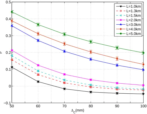
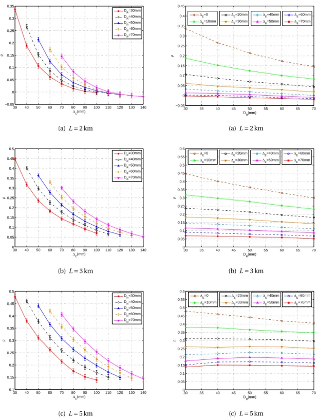
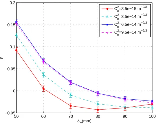
Le Chapitre 3 est consacré à l’étude des évanouissements corrélés pour un système FSO util-isant la diversité spatiale. Cette étude est basée principalement sur la méthode de simulation d’écrans de phase. Après une introduction sur cet outil, nous expliquons comment fixer ses paramètres ainsi que la méthode de calcul du coefficient de corrélation entre les évanouisse-ments correspondant aux différents sous-canaux. Ensuite, nous considérons comme cas d’étude un système FSO avec la diversité à la réception (c’est-à-dire, utilisant des lentilles multiples), puis nous évaluons le coefficient de corrélation et l’impact de différents paramètres du système sur ce dernier. Nous montrons que le coefficient de corrélationρ augmente avec la distance de la liaison
L et le diamètre de l’ouverture du récepteur DR, tandis que une augmentation de l’espacement
entre les lentilles conduit à une réduction deρ. Pour des valeurs grandes de L, nous montrons queρ dépend essentiellement de la séparation entre les lentilles ∆Eet est quasiment indépendant
de DR. De plus, pour un système FSO MIMO (Multiple-Input Multiple-Output), nous vérifions
le modèle de Kronocker: ce modèle consiste à obtenir la matrice de corrélation globale à partir des matrices de corrélation, en considérant séparément un système multifaisceaux et un système multi-lentilles.
Etant donné la complexité calculatoire de la méthode des écrans de phase, nous avons eu recours aux simulations de Monte Carlo et aux méthodes analytiques pour évaluer les perfor-mances du système. Ces derniers font respectivement l’objet des Chapitres 4 et 5. Le Chapitre 4 est dédié à l’étude des performances d’un système FSO à diversité spatiale dans les conditions des évanouissements corrélés par les simulations de Monte Carlo. Pour cela, nous proposons une méthode numérique ayant pour objectif d’effectuer un tirage des variables aléatoires de distri-butionΓΓ , correspondant aux coefficients d’évanouissement des sous-canaux. La méthode pro-posée est basée sur la décomposition du coefficient de corrélation en deux coefficients de corréla-tion partielle: ils correspondent respectivement aux fluctuacorréla-tions d’intensité à grande et à petite échelle. A travers une analyse détaillée et exhaustive basée sur la théorie de scintillation, nous élucidons la corrélation en provenance des turbulences à grande et à petite échelle. Nous pro-posons une série de critères pour effectuer la décomposition de la corrélation. Ensuite nous les
Résumé étendu 9
validons en utilisant des simulations des écrans de phase. Par ailleurs, à l’aide des simulations de Monte Carlo, nous démontrons qu’en pratique nous pouvons adopter la simple solution basée sur l’hypothèse deρY = 0, quelque soit le régime de turbulence.
En utilisant la méthode proposée pour le tirage des variablesΓΓ , nous évaluons ensuite les per-formances des systèmes FSO, dans les deux cas d’une photodiode PIN et d’une APD en réception. Un point intéressant fut que la corrélation des évanouissements n’impacte pas la sélection du gain optimal de l’APD.
Dans le Chapitre 5, nous étudions deux approches analytiques pour évaluer les performances d’un système FSO dans les conditions des évanouissements corrélés. Ces méthodes sont basées sur la distribution de la somme des variables aléatoiresΓΓ . La première méthode consiste à ap-proximer la somme des variables aléatoiresΓΓ par une distribution α-µ . Le taux d’erreur binaire (BER pour Bit-Error Rate) est ensuite calculé en moyennant les BERs conditionnels sur la den-sité de probabilitéα-µ . Cette approche permet de prédire les performances du système avec une bonne précision pour une diversité d’ordre 2. Toutefois, sa précision diminue en augmentant l’ordre de diversité, notamment pour les coefficients de corrélation relativement grands. La deux-ième méthode est basée sur la fonction génératrice des moments (MGF pour Moment Generating
Function) de la somme des variables aléatoiresΓΓ . Nous n’avons pas pu obtenir une expression
analytique pour la MGF: nous considérons une représentation en série de la MGF et approximons cette dernière par l’approximation de Padé afin d’analyser les performances du système. Le seul inconvénient de cette méthode est que nous ne pouvons pas atteindre des BERs plus faibles que 10−7à cause des problèmes numériques liés à l’approximation de Padé.
Après avoir effectué l’étude de l’impact des évanouissements corrélés sur les performances du système, nous nous intéressons dans le Chapitre 6 aux schémas de transmission pour les sys-tèmes FSO à diversité d’émission. Pour un système classique MIMO, nous cherchons les sché-mas espace-temps appropriés à l’émission afin d’optimiser les performances du système ainsi que le débit de transmission. En particulier, nous étudions l’intérêt des schémas à grande efficac-ité spectrale tels que le multiplexage spatiale (SMux) et la modulation optique spatiale (OSM). Nous comparons leurs performances avec les schémas de code à répétition (RC) et les codes espace-temps en bloc orthogonaux (OSTBC). Pour cela, nous présentons d’abord un état de l’art du codage espace-temps pour les systèmes MIMO FSO. Ensuite nous présentons quelques résul-tats numériques sur la comparaison des performances de différents schémas de transmission. En supposant l’absence de contraintes sur la bande passante du système, nos résultats confirment la quasi-optimalité du schéma RC qui permet d’exploiter pleinement la diversité spatiale. Il per-met une meilleure performance par rapport aux autres schémas et, de plus, a l’avantage d’une complexité plus faible aux niveaux du codage et du décodage. Toutefois, si nous sommes limités en bande passante, à cause de la vitesse limitée des composants optroniques par exemple, nous aurions éventuellement intérêt à aller vers des schémas espace-temps à des taux plus élevés.
Dans le Chapitre 7, nous présentons quelques résultats expérimentaux pour étudier l’efficacité des techniques classiques de réduction d’évanouissements, à savoir, l’utilisation d’une grande
pupille (aperture averaging) et la diversité à la réception, dans un environnement contrôlé en lab-oratoire. Ces mesures sont réalisées grâce au soutien du consortium COST IC1101 Opticwise et en collaboration avec le laboratoire OCRG de l’Université Northumbria à Newcastle. Après la descrip-tion des la configuradescrip-tion de la maquette de transmission FSO, développée au laboratoire OCRG, nous expliquons les méthodes de caractérisation des turbulences générées artificiellement. Les performances d’un système avec un laser et deux lentilles sont ensuite évaluées pour différents diamètres du récepteur. Ceci a pour objectif de confirmer les résultats théoriques sur la méthode de “aperture averaging” et diversité à la réception. De plus, pour le cas du système utilisant deux lentilles à la réception, nous étudions et quantifions la corrélation des évanouissements du canal. Enfin, les conclusions générales de cette thèse et quelques perspectives pour les travaux futurs sont présentées dans le Chapitre 8.
Chapter 1
General Introduction
Contents1.1 Free-space optics overview . . . . 11 1.1.1 Brief history . . . 11 1.1.2 Advantages and applications of FSO . . . 13 1.1.3 Challenges of FSO . . . 15 1.2 Thesis objectives . . . . 15 1.3 Thesis overview and contributions . . . . 16 1.3.1 Thesis outline . . . 16 1.3.2 Author’s contributions . . . 18 1.3.3 Author’s publications . . . 18
1.1 Free-space optics overview
Free-space optical (FSO) communication is one of the key technologies for realizing very high rate wireless data transmission. FSO is a line-of-sight (LoS) technology by which information data is conveyed by a modulated light beam from one point to another in free space. It provides numer-ous advantages and has been used in several applications and markets so far.
1.1.1 Brief history
The idea of transmitting messages through the air by means of visual signals goes back to long time ago and can be considered as one of mankind’s oldest forms of communication. During the Roman and Greek age, polished metal plates were used as mirrors to reflect sunlight for signaling purposes. For long-range communication, fire beacons placed on high points were lit from one point to another to deliver messages. Also, ancient Chinese used smoke signals to communicate the information on enemy movements between the army units along the Great Wall. The true
optical telecommunication could be said to start at the end of the 18thcentury with the emergence of the optical semaphore telegraph invented by Claude Chappe. In 1880, a “modern” wireless optical communication setup using electronic detectors, called “Photophone”, was invented by Alexander Graham Bell. There, the speaker’s voice was modulated onto the reflected sunlight by a voice-vibrating foil diaphragm. After propagating over a range of about 600 feet in the air, the modulated sunlight was collected by a photoconductive selenium cell connected to a pile and ear-phones. However, the setup was transitory because of the small transmission lengths and the intermittence of the sun radiation [1–3].
During the following century, radio frequency (RF) and fiber-optic communications devel-oped very fast and dominated the telecommunication market. Nevertheless, several early FSO experiments of historical interest, recorded in the early 1960s into 1970s, are worth to mention [4]. Shortly after the 632.8 nm Helium-Neon (He-Ne) laser was discovered, the first demonstration of long distance laser communication through the atmosphere was given by a Hughes group in 1962 over a range of 30 km. A photomultiplier was used to detect the light signal of intensity modu-lation, and a high-pass filter was employed to reduce the effects of the optical scintillation. In May 1963, a similar transmission link using a voice-modulated He-Ne laser beam was established from Panamint Ridge to San Gabriel Mountain by Electro-Optics Systems, and the link distance was extended to 190 km. The TV-over-laser transmissions with the modulation bandwidths of 1.7 and 5 MHz were achieved by North American Aviation and Hughes in 1963, respectively. A full duplex 632.8 nm He-Ne laser communication link over a total distance of 14 km, built in Japan by Nippon Electric Company (NEC) around 1970, was the first FSO link to handle a commercial traffic. However, during the boom period of fiber-optics communications, the civil FSO lost its in-terest; nevertheless, its development was never stopped in space application laboratories, mainly European Space Agency (ESA) and National Aeronautics and Space Administration (NASA). For in-stance, near-Earth lasercom systems were demonstrated under the programs of Geosynchronous Lightweight Technology Experiment (GeoLITE) and Global-scale Observations of the Limb and Disk (GOLD) in USA, and Semiconductor Intersatellite Link Experiment (SILEX) in Europe. The Mars Laser Communications Demonstration (MLCD) Project was a Mars mission that was orig-inally intended to launch by NASA in 2009 and would have established an interplanetary laser communication link between Earth and Mars with the aim of achieving a high transmission rate of up to 10 Megabits per second (Mbps). The Lunar Laser Communications Demonstration (LLCD) project, sponsored by NASA, aims at demonstrating the world’s first free-space laser communica-tion system that can operate over a range of about 400,000 kilometers that is ten times larger than the near-Earth ranges that have been demonstrated to date. It will demonstrate high-rate (up to 622 Mbps) laser communication from a lunar orbit to a terminal on Earth.
In parallel with space-application researches and with the progresses made in the fabrication technology of optical transmission and detection components, FSO also received increasing at-tention in military applications due mainly to its high inherent security.
1.1. FREE-SPACE OPTICS OVERVIEW 13
the growing demand for higher data rates and higher-quality connectivity from commercial cus-tomers. In particular, FSO can help service providers reach the customers’ demand without the prohibitive costs of deploying fiber. This market of FSO spawned many manufacturing compa-nies, e.g., Lightpointe, MRV, CableFree, and MOSTCOM, and a great deal of the commercial FSO systems have been designed and manufactured. Some of them allow transmission with data rates of up to several Gigabits per second (Gbps) and link spans of up to several kilometers [5, 6]. In 2012, the global market for devices used in commercial FSO communication systems grew by 13% on the previous year, reaching of $ 30 million [7]. A current forecast by market researchers at Elec-troniCast Consultants reports that the market for commercial FSO systems will nearly double by 2018 [7].
Note that optical wireless communication (OWC) is also a complementary technology to RF communication for relatively short-range communications such as indoor communication through point-to-point wide or narrow LoS links, or diffuse transmissions [8, 9]. Especially, vis-ible light communication (VLC) has recently received particular attention due to the potential of white emitting diodes (LEDs) for wireless data transmission at the same time of light-ing use [8–12]. Today, other variations of OWC are employed in a diverse range of communica-tion applicacommunica-tions: the simple TV remote control, Infrared Data Associacommunica-tion (IrDA) ports [13], very short-range optical interconnects within integrated circuits [14], wireless health-care monitoring in hospitals [15], sensor networks [16], ship-to-ship and ship-to-shore high-rate communication, underwater transmission [17], etc., with wavelengths ranging from infrared to visible and ultravi-olet.
In this thesis, we focus on terrestrial FSO communication links, where the propagation path is horizontal and close to ground.
1.1.2 Advantages and applications of FSO
Compared with RF communication, FSO offers numerous advantages, including high capacity, unregulated spectrum, ease of deployment, transmission security, cost effectiveness, and robust-ness to electromagnetic interference as detailed in the following [18–22].
• High data rate: By working near infrared (IR) wavelengths, an FSO link has a very high optical bandwidth available, and can carry a huge amount of information. This allows high rate data transmission that can exceed several Gbps.
• Unlicensed spectrum: Unlike RF communication for which spectrum utilization is expen-sive and strictly regulated (e.g. by Federal Communication Commission (FCC) in USA, the Office of Communication (Ofcom) in UK, and Autorité de Régulation des Communications Électroniques et des Postes (ARCEP) in France), the optical spectrum is still unlicensed and absolutely free at the present time.
usually used in practical FSO systems are compact and relatively light. These portable termi-nals are easy-to-install on the roof of buildings or behind the windows. As a result, a point-to-point link can be typically established in about one hour or less as long as a suitable line of sight is identified [23].
• High transmission security: FSO is a directional point-to-point transmission using very narrow beams (the divergence angle of the beam is typically smaller than 10 mrad), which makes it almost impossible to intercept. In addition, FSO terminals require a complete and uninterrupted link for successful operation. If someone attempts to intercept the signal by placing a detector in the beam propagation path, it immediately results in beam blockage and communication interruption [24].
• Cost effectiveness: Providing fiber-like capacity of data rates up to several Gbps, FSO offers a cost of about 4$/Mbps/month as it requires little maintenance and inexpensive compo-nents compared to RF systems. This cost is half as expensive as that with RF systems [23]. On the other hand, compared to the traditional fiber-optic communication systems, the installa-tion of an FSO link can be done very quickly and with relatively low cost.
• Electromagnetic interference immunity: Due to the use of narrow beams, several FSO links can operate by close distance without incurring any interference.
• Efficient use of energy: The small beam divergence used in FSO systems allows more effi-cient use of energy, compared to RF links. The latter suffers from energy leakage from antenna sidelobes and also from much less focalized transmitter antenna pattern. In particular, this property is a key reason for using FSO in deep space applications, except for high transmis-sion rates [25].
The advantages of the FSO technology make it very attractive for various applications. In par-ticular, FSO is firstly argued as the suitable solution to the “last mile" problem, the bottleneck restricting high speed communication links for Internet users at home [26, 27]. In a few years, it became as the key building block for most wide-area free-space data networks, especially for inter-building communication and LAN-to-LAN connectivity. FSO can also be used for more spe-cific applications such as fiber backup because of its fiber-like capacity [20]. It can also be used in the locations where fiber installation is impossible or too expensive. On the other hand, thanks to its portable terminals and rapid deployment, FSO is adopted as a suitable solution for disas-ter recovery and temporary links. The high security of FSO links makes it specially attractive for military communication, in particular, in network-centric operational links where information is fundamental for gaining superiority in the battlefield [28]. Other military FSO applications include inter-satellite, space-to-air, air-to-air, air-to-ground, or space-to-ground links.
1.2. THESIS OBJECTIVES 15
1.1.3 Challenges of FSO
In terrestrial FSO systems, the system performance can be severely affected by the atmosphere which has a detrimental impact on the optical beam. More specifically, the performance of an FSO link can be degraded due to two main mechanisms [3]: (i) the reduction in the detected op-tical power level due to atmospheric attenuation, which is caused by meteorological phenomena (e.g., fog, rain, snow, or haze), for instance, causing absorption and scattering of the optical beam; (ii) random optical power fluctuations of the received signal due to the atmospheric turbulence, which is one of the main limitations under clear weather conditions [29] (see Section 2.3).
On the other hand, the performance of an FSO link also depends upon the installation char-acteristics [30]. For instance, due to the narrowness of the light beams and the limited receiver’s field-of-view (FOV), the FSO transceivers’ alignment is very susceptible to building movements, which can be induced by temperature variations, strong wind, and even human activity (e.g. walk-ing and shuttwalk-ing doors). The incurred misalignment can substantially degrade and even interrupt the communication. Possible solutions are to increase the beam divergence (which, in turn, re-sults in higher geometric loss), using an automatic tracking mechanism at the transmitter or/and at the receiver (which results in increased system cost and complexity) [30].
FSO transmission modules can be installed behind windows instead of being mounted at rooftops. This is especially advantageous for connecting individual customers who may not have access to a building’s roof or do not wish to pay for it. However, about 4% of the optical power will be reflected by each surface of an uncoated glass window when the optical signal passes through it. So, if we consider one window at each side, the optical signal will be attenuated about 16% in total.
Lastly, the issue of eye safety has to be carefully treated according to the laser safety stan-dards [18]. This limits the transmit optical power, and hence, we can not attempt to achieve a very high performance by persistently increasing the power. Other adverse effects are background radiations and line-of-sight obstructions.
1.2 Thesis objectives
This dissertation focuses on the impairment of atmospheric turbulence in FSO systems and con-siders the use of spatial diversity to reduce the effect of the corresponding channel fading.
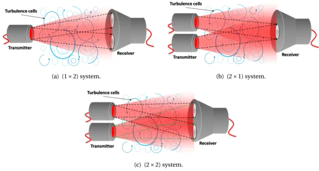
To mitigate the turbulence-induced channel fading, spatial diversity is considered as a prefer-able solution that can be realized by employing multiple apertures at the receiver and/or multiple beams at the transmitter [31–34]. In fact, this technique loses its efficiency under the conditions of correlated fading on the underlying sub-channels that occur in practice. We propose solutions to accurately model the fading channel and to evaluate the true system performance under corre-lated fading conditions. Most of our analyses are based on the Gamma-Gamma (ΓΓ) fading model, which has been shown to accurately model the intensity fluctuations under different turbulence
strength conditions [35].
The key questions we try to answer in this thesis are how to evaluate the fading correlation, and how to integrate this correlation into theΓΓ channel model in view of evaluating the system performance. We also look for appropriate signaling schemes for the case of transmit diversity systems. To attain these objectives, we have proceeded according to the following steps:
• Reviewed the fundamentals of the terrestrial FSO systems, especially concerning channel modeling and fading mitigation (treated in Chapter 2)
• Quantified the fading correlation coefficients in space-diversity FSO systems via wave-optics (WO) simulations (treated in Chapter 3).
• Evaluated the performance of space-diversity FSO systems over correlatedΓΓ fading chan-nels by Monte-Carlo (MC) simulations and via analytical approaches (treated in Chapters 4 and 5).
• Investigated the suitability of different space-time (ST) schemes for FSO systems employing transmit diversity to achieve an optimal trade-off between transmission rate and link perfor-mance (treated in Chapter 6).
• Investigated the effects of aperture averaging, spatial diversity, and fading correlation through a set of experiments carried out in a controlled laboratory environment (treated in Chapter
7).
1.3 Thesis overview and contributions
1.3.1 Thesis outlineThis dissertation contains 8 chapters, including this Introduction as Chapter 1.
Chapter 2 presents the fundamentals of FSO communication regarding the three main parts
of transmitter, atmospheric channel, and receiver. We start by the optical transmitter and provide details on signal modulation and the characteristics of laser diodes. Concerning the atmospheric channel, we explain the atmospheric loss along the propagation path arising from atmospheric attenuation and optical scintillation. Also, the notion of link budget for an FSO link is introduced briefly. At the receiver, we discuss the process of photo-detection and signal demodulation. Next, focusing on the atmospheric turbulence, also referred to as optical scintillation, we introduce a number of fading mitigation methods to improve the robustness of the FSO link. Among these methods, we focus on the spatial diversity techniques as they appear to be more suitable from a practical implementation point of view. Finally, we summarize the principal assumptions that we make in the framework of this thesis.
Chapter 3 is devoted to the study of fading correlation in space-diversity FSO systems. This
1.3. THESIS OVERVIEW AND CONTRIBUTIONS 17
through the atmosphere. We first introduce the WO simulation tool and explain how to optimally set the corresponding simulation parameters and also how to calculate the channel fading and correlation coefficients. Then, we consider a receive-diversity FSO system as case study, and eval-uate the fading correlation coefficients between the underlying sub-channels. The impact of dif-ferent system parameters on the fading correlation is also discussed. Comparing our results with those reported in [36], we also present some discussions on the fading correlation for the cases of multiple-input single-output (MISO) and multiple-input multiple-output (MIMO) FSO systems. In particular, we validate by means of WO simulations, the Kronecker model suggested in [37] to obtain the correlation matrix for the MIMO FSO systems.
Chapter 4 considers performance evaluation of space-diversity FSO systems under the
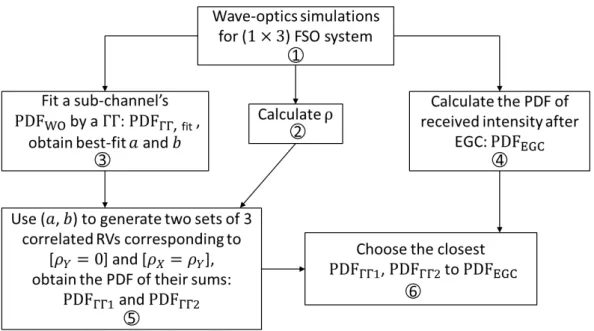
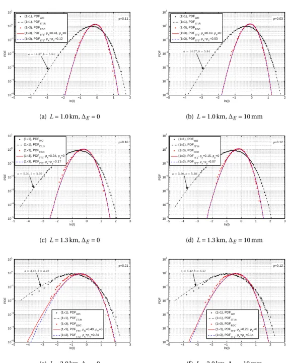
con-dition of correlated fading via MC simulations. To do this, we develop a numerical method to generate correlatedΓΓ random variables (RVs) corresponding to the sub-channels’ fading coef-ficients in a space-diversity FSO system. The proposed method is based on the decomposition of the correlation coefficient into two partial correlation coefficients corresponding to large- and small-scale intensity fluctuations in the corresponding sub-channels. Through an extensive and detailed analysis based on scintillation theory, we bring clearance on the fading correlation arising from large and small-scale turbulence. We propose a set of criteria to do the correlation decompo-sition and validate them by means of WO simulations. In addition, the performance of P-i-N (PIN)-and avalanche photodiode (APD)-based FSO receivers is evaluated by MC simulations using the proposed RV generation method.
After considering an MC simulation approach in Chapter 4, in Chapter 5 we investigate two analytical approaches in order to evaluate the performance of space-diversity FSO systems under arbitrarily correlatedΓΓ fading conditions. These methods are based on the distribution of the sum of correlatedΓΓ RVs. The first one approximates the sum of multiple correlated ΓΓ RVs by an
α-µ RV. Then, the system average bit error rate (BER) performance is calculated by averaging the
conditional BER over the probability density function (PDF) of the approximateα-µ distribution. The second method is based on the moment generating function (MGF) of the sum ofΓΓ RVs. Since we could not obtain a closed-form expression for the MGF yet, we alternatively provide an infinite series representation of the MGF and use the Padé approximants of this series to analyze the system performance.
After studying the impact of correlated fading, we focus on transmit-diversity FSO systems and, in particular, on MIMO FSO systems in Chapter 6. We investigate signal transmission schemes for the transmit-diversity structures. More specifically, for the case of MIMO systems, we consider the important issue of how to combine the information-bearing symbols at the trans-mitter in order to optimize the system performance and the transmission rate; what is commonly called ST coding. We firstly present a state-of-the-art on ST coding in MIMO FSO systems, and then present some numerical results on the performance comparison of different ST schemes.
In Chapter 7, we present some experimental results to investigate the effectiveness of the two fading mitigation techniques of aperture averaging and receive diversity in a controlled laboratory
environment. We describe the configurations of the experiment setup and briefly explain turbu-lence measurement and performance evaluation of the FSO link. The performance of a single-laser dual-aperture system with different aperture diameters is evaluated, which validates the pre-dicted theoretical improvement by aperture averaging and receive diversity. In addition, we inves-tigate the fading correlation issue for a dual-aperture FSO system. These experiments have been conducted thanks to the collaborations of Institut Fresnel and Optical Communication Research Group (OCRG), and with the support of Opticwise COST Action IC1101.
Chapter 8 concludes the thesis and gives some perspectives for future work.
1.3.2 Author’s contributions
The main author’s contributions in this thesis are briefly mentioned in the following.
• Evaluated the fading correlation in receive-diversity FSO systems, and studied the impact of system parameters on the fading correlation. These results were generalized to other space-diversity systems, and the Kronecker model for fading correlation in MIMO FSO systems was validated.
• Proposed a method to generate arbitrarily correlated ΓΓ channels in order to account the effect of fading correlation on the performance of space-diversity FSO systems. Using this method, the BER performances of PIN- and APD-based systems over correlatedΓΓ channels were evaluated via MC simulations, and the effect of fading correlation on the optimal APD gain was demonstrated.
• Developed analytical approaches to evaluate the performance of space-diversity FSO systems over correlatedΓΓ channels, based on approximations to the sum of arbitrarily correlated ΓΓ RVs.
• Contrasted the already-proposed ST schemes for MIMO FSO systems, and validated the op-timality of the repetition coding (RC) scheme.
• Experimentally investigated the effect of aperture averaging and receive diversity as well as the fading correlation for an FSO link in a controlled laboratory environment thanks to the collaboration with the OCRG laboratory. Also, fading correlation in a receive-diversity system was evaluated.
1.3.3 Author’s publications
1. G. Yang, M. A. Khalighi, Z. Ghassemlooy, and S. Bourennane, “Performance evaluation of receive-diversity free-space optical communications over correlated Gamma-Gamma fading channels,” Applied Optics, vol. 52, no. 24, pp. 5903–5911, Aug. 2013.
1.3. THESIS OVERVIEW AND CONTRIBUTIONS 19
2. G. Yang, M. A. Khalighi, S. Bourennane, and Z. Ghassemlooy, “Approximation to the sum of two correlated Gamma-Gamma variates and its applications in free-space optical communi-cations,” IEEE Wireless Communications Letters, vol. 1, no. 6, pp. 621–624, Dec. 2012.
3. G. Yang, M. A. Khalighi, Z. Ghassemlooy, and S. Bourennane, “Performance Evaluation of Correlated-Fading Space-Diversity FSO Links,” accepted by International Workshop on
Opti-cal Wireless Communications (IWOW), Oct. 2013, Newcastle upon Tyne, UK.
4. G. Yang, M. A. Khalighi, Z. Ghassemlooy, and S. Bourennane, “Analytical Evaluation of the Performance of Space-Diversity FSO Systems under Correlated Fading Conditions,” Input
Document to the COST IC1101 MC Meeting, Apr. 2013, Prague, Czech Republic.
5. G. Yang, S. Rajbhandari, Z. Ghassemlooy, M. A. Khalighi, and S. Bourennane, “Experimental works on free-space optical communications with aperture averaging and receive diversity in a controlled laboratory environment,” Actes des Journées d’études Algéro-Françaises de
Doc-torants en Signal, Image & Applications, Dec. 2012, Alger, Algeria.
6. G. Yang, M. A. Khalighi, T. Virieux, S. Bourennane, and Z. Ghassemlooy, “Contrasting space-time schemes for MIMO FSO systems with non-coherent modulation,” International
Work-shop on Optical Wireless Communications (IWOW), Oct. 2012, Pisa, Italy.
7. G. Yang, M. A. Khalighi, and S. Bourennane, “Performance of receive diversity FSO systems under realistic beam propagation conditions,” IEEE, IET Int. Symposium on Communication
Systems, Networks and Digital Signal Processing(CSNDSP), pp. 1–5, July 2012, Poznan, Poland.
8. G. Yang, M. A. Khalighi, S. Bourennane, and Z. Ghassemlooy, “Fading Correlation and Analyti-cal Performance Evaluation of Space-Diversity Free-Space OptiAnalyti-cal Communication Systems,”
Chapter 2
Fundamentals of FSO Communication
Contents 2.1 Introduction . . . . 21 2.2 Transmitter . . . . 22 2.2.1 Signal modulation . . . 23 2.2.2 Optical source . . . 23 2.3 Atmospheric channel . . . . 24 2.3.1 Atmospheric attenuation . . . 24 2.3.2 Turbulence-induced fading . . . 25 2.3.3 Link margin . . . 25 2.4 Receiver . . . . 26 2.4.1 Photodetector . . . 26 2.4.2 Signal demodulation . . . 27 2.5 Study of turbulence-induced fading . . . . 27 2.5.1 Statistical models . . . 282.5.2 ΓΓ channel model . . . 28
2.5.3 Wave-optics simulation . . . 30 2.5.4 Experimental study . . . 31 2.6 Methods to mitigate turbulence-induced fading . . . . 32 2.7 Channel modeling for space-diversity FSO systems . . . . 34 2.8 Chapter summary . . . . 35
2.1 Introduction
Consider a typical FSO communication link between a transmitter and a receiver in LoS. At the transmitter, the information bits are converted into an electrical signal, which modulates the laser
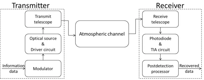
Figure 2.1 — The general block diagram of a terrestrial FSO system.
to generate an optical signal. This latter propagates through the atmospheric channel towards the receiver. At the receiver, generally a PIN diode or an APD is used to convert the optical signal back to an electrical signal before data detection. The block diagram of a typical FSO system is shown in Fig. 2.1, where three main blocks of the transmitter, atmospheric channel and receiver are shown, which will be briefly described in Sections 2.2, 2.3 and 2.4, respectively. Different ways of studying the turbulence-induced fading are explained in Section 2.5. Also, methods to improve the robust-ness of the FSO link against the atmospheric turbulence are described in Section 2.6. Among these methods, spatial diversity seems to be practically more suitable for most FSO systems. We present in Section 2.7 some previously proposed channel models for space-diversity FSO systems, and also explain our main contributions on this subject. At last, we summarize the principal assumptions we make throughout this thesis in Section 2.8.
2.2 Transmitter
A typical FSO transmitter is composed of a modulator, an optical source and a transmit telescope, as illustrated Fig. 2.1 [20, 21]. The binary bits from the information source are modulated onto an optical carrier. More precisely, the intensity of the optical source (usually a laser diode) is modu-lated by the information bits, which is achieved by varying the driving current of the optical source directly in accordance with the transmitted data or via an external modulator such as a symmetri-cal Mach-Zehnder interferometer [21]. Then, the modulated light beam passes through the trans-mit telescope in order to set its width and divergence. In the following subsections, we will briefly describe the signal modulation and the optical source.
2.2. TRANSMITTER 23
2.2.1 Signal modulation
In optical communication, intensity modulation (IM) is the most widely used modulation scheme by which the optical power of a source is varied in accordance with the modulating signal. For the case of FSO communication, two IM techniques ofON-OFFkeying (OOK) and pulse position modulation (PPM) have been widely considered so far [22, 32, 38–40]. For the non-return-to-zero (NRZ) OOK modulation, a binary bit ‘1’ or ‘0’ is represented by the presence or absence of an opti-cal pulse of intensity Ptin each bit duration Tb, respectively. Despite of the design and
implemen-tation simplicity of OOK, its optimal detection requires that the detection threshold level be set in accordance with the channel fading coefficient. On the other hand, for the Q-ary PPM modulation scheme, each block of log2Q binary bits is mapped into one of Q possible symbols. Each symbol
consists of an optical pulse of constant intensity Pt occupying one slot of the duration Ts, along
with (Q− 1) off slots. Hence, the information bits are encoded by the position of the pulse within a symbol. Compared with OOK, PPM has a higher energy efficiency and does not require adaptive thresholding for optimal signal detection [2, 38]. However, it requires a more complex transceiver design due to synchronization requirements, and also needs a higher bandwidth than OOK. For the sake of modeling simplicity, we only consider the NRZ OOK scheme for signal modulation in this thesis.
2.2.2 Optical source
The optical source generates the optical signal from an electrical signal by means of the modulator. It usually consists of a semiconductor laser with direct modulation, which is realized by varying the current supply of the laser to directly modulate its output power. To be used in terrestrial FSO systems over ranges up to several kilometers, the laser diodes should be capable of operat-ing at high power levels and high-speed modulation, as well as operatoperat-ing over a wide temperature range without major performance degradation. Also, they should have a long mean time between failures (MTBF), a small footprint, and low power consumption [22, 30]. For these requirements, two types of laser diodes are usually used: vertical-cavity surface-emitting lasers (VCSELs), and distributed-feedback (DFB) lasers [41]. They operate at the optical wavelengths ofλ = 850 and 1550 nm, respectively, which fall inside the atmospheric transmission windows where the atmo-spheric attenuation on the optical signal is relatively very low [30]. On the other hand, referring to the laser safety standards, the allowable transmission power of lasers operating at 1550 nm is higher than that of lasers operating at 850 nm. Hence, DFB lasers can work over longer ranges and at higher power levels. As relatively long distance links are considered in this thesis, we choose to work with the optical wavelength ofλ = 1550 nm. In addition, most laser diodes emit beams that approximate the Gaussian profile. To this reason, we consider the Gaussian-wave propagation model throughout this manuscript.
2.3 Atmospheric channel
After being launched from the transmitter, the light beam passes through the atmospheric chan-nel, where the majority of optical power loss occurs. This loss depends on the atmospheric con-ditions, in general, and is commonly divided into two factors of atmospheric attenuation and turbulence-induced fading, as explained in the following.
2.3.1 Atmospheric attenuation
Atmospheric attenuation is considered as the reduction in the intensity of optical beam propagat-ing through the atmosphere. It is caused by the meteorological phenomena such as fog, rain and snow, and also by dust, haze, low clouds, etc. In general, this attenuation arises from two effects: absorption and scattering.
• Absorption: While an optical beam propagates in the atmosphere, some of the photons are absorbed by the molecular constituents (e.g., water vapor, CO2, ozone) and their energy is converted into heat [21]. This is a wavelength-dependent process, and the low-loss atmo-spheric transmission windows are centered on 850, 1300, and 1550 nm [18]. As mentioned previously, the optical wavelengths ofλ = 850 and 1550 nm are widely used in FSO systems to coincide with these windows [30]. Indeed, in these windows, the atmospheric attenuation is dominated by scattering.
• Scattering: By the scattering effect, a part of photons are deflected from their initial forward direction, giving rise to spatial, angular, and temporal spread of the beam. This effect depends on the sizes of the particles present along the propagation path. When the sizes of the parti-cles are much larger than the optical wavelength (which is the case for rain, snow and hail, for example), the resulting attenuation is relatively low. Especially, for short distance links, these particles are not considered as major factors impacting FSO availability [42]. Nevertheless, they can significantly impair the performance of an FSO link in the case of heavy rainfall or snow. On the other hand, for the particles of diameters on the order of the optical wavelength (e.g., fog, haze and dust), the scattering process is classified as Mie scattering and with a re-sulting high attenuation coefficient. As a matter of fact, in FSO communication, fog and haze are considered as the most detrimental impairments [43]. Finally, when the sizes of particles are much smaller than the wavelength (e.g., air molecules and fine ash), the Rayleigh scatter-ing model applies. Fortunately, the correspondscatter-ing attenuation coefficient is very small and can be neglected compared to that of Mie scattering.
When an FSO system works under clear weather conditions, the atmospheric attenuation is somehow tolerable, but another atmospheric effect becomes the dominant impairment factor, i.e., optical scintillation, as explained in the following subsection.
2.3. ATMOSPHERIC CHANNEL 25
2.3.2 Turbulence-induced fading
Under clear weather conditions, the inhomogeneities of the temperature and pressure in the at-mosphere results in the variations of the air refractive-index, what is called atmospheric turbu-lence. The turbulence acts like a series of lenses of different sizes that cause refractive and diffrac-tive effects on the light beam. The resultant irradiance fluctuations at the receiver can substantially degrade the performance of an FSO link. This phenominon is commonly called optical scintilla-tion or turbulence-induced fading [44, 45]. The Rytov varianceσ2R is widely used as a measure of the strength of atmospheric turbulence, which is defined for a plane wave as [35]:
σ2
R= 1.23Cn2k7/6L11/6, (2.1)
where Cn2, k, and L are the refractive-index structure parameter, optical wave number given by
2π/λ, and link distance, respectively. Note that Cn2 is usually assumed to be constant along the propagation path near the ground where we usually have homogeneous turbulence conditions. Typically, the turbulence is classified into three regimes [35]:
• Weak turbulence regime, when σ2
R< 1;
• Moderate turbulence regime, when σ2
R≈ 1;
• Strong turbulence regime, when σ2
R> 1.
In addition, the commonly called saturation regime of the turbulence conditions is defined by
σ2
R→ ∞ [35]. However, the Rytov variance only represents the irradiance fluctuations in the weak
turbulence regime, and it is inadequate for other regimes. To measure the irradiance fluctuations, a more suitable parameter is the scintillation index (SI)σ2I that is the normalized variance of the irradiance, and defined as [46]:
σ2
I=
〈I2〉
〈I〉2− 1, (2.2)
where I denotes the received optical intensity, and〈·〉 represents the ensemble average. Through-out this thesis, we consider the clear weather conditions and focus on the effect of the turbulence-induced fading in FSO channels.
2.3.3 Link margin
Given the atmospheric attenuation, a link margin should be considered before installation. This margin represents the maximal amount of power loss that can be tolerated for an FSO link achiev-ing an expected error rate. Typically, an FSO link budget takes into account the factors of transmit optical power1Pt, receiver sensitivity S, optical system loss Lsys, misalignment loss Lali, and ge-ometric loss Lgeo. More precisely, Pt and S represent the optical power launched from the laser
diode and the minimum required received power for signal detection, respectively. Lsysrefers to
the power loss that occurs as the optical beam passes through the optical devices (e.g., the tele-scopes at the transmitter and the receiver). It mainly arises from surface reflection and, hence, can be neglected by using lenses with antireflective coating [30]. Lali is caused by the imperfect alignment between the transmitter and receiver, which can be canceled with the use of a tracking system2. On the other hand, due to the divergence of the light beam, the beam spot of the laser at the receiver is much larger than the receiver aperture. The corresponding lost optical power is denoted by Lgeo. Overall, the link margin for the FSO system is calculated as follows:
Mtur= Pt− S − Lsys− Lgeo− Lali(in dB). (2.3) Several typical examples for link margin calculation can be found in [30]. For the sake of modeling simplicity, we negelect Lsys, Lgeoand Lali, and consider Pt as the average received optical power,
assuming a “normalized” channel, i.e., setting the average turbulence-induced fading to one.
2.4 Receiver
As shown in Fig. 2.1, a typtical FSO receiver consists of a receive telescope, a photodetector (PD) together with a transimpedance amplifier (TIA), and a postdetection processor. The incident light beam is firstly collected and focused onto the PD through the telescope [20]. Note that the optical filters, usually employed prior to PD, perform spectral optical filtering to reduce the background noise level. Next, the captured optical signal is converted back to the electrical signal by the PD. The resulting electrical signal is then amplified, filtered and sampled before signal detection. We provide the details on the PD and signal demodulation in the two following subsections.
2.4.1 Photodetector
The PD is a square-law optoelectronic transducer that generates an electrical signal whose power is proportional to the square of the optical field impinging on its surface. Since the optical signal is generally weak after having travelled through the communication channel, the PD must meet stringent performance requirements such as high sensitivity within its operational range of wave-lengths, a low noise level and an adequate bandwidth to accommodate the desired data rate. The effect of temperature fluctuations on the response of the PD should be minimal and the device must equally have a long operating life [41]. The wavelengths at which the detector responds to light depend on the detector’s material composition. The PDs fabricated based on Indium Gallium Arsenide (InGaAs) are usually used to detect the wavelength ofλ = 1550 nm which we mostly con-sider in this thesis. On the other hand, two types of PDs are usually used in FSO communication: PIN photodiode and APD. PIN diodes are usually used in FSO systems working at ranges up to a few kilometers [24] due to their limitation of relatively low responsivity. Also, a drawback of using 2For instance, an automatic tracking system uses a mechanical gimbal and a position sensing diode (PSD) to track a
2.5. STUDY OF TURBULENCE-INDUCED FADING 27
PIN diodes is that the receiver becomes thermal noise-limited [44]. This can be effectively over-come by using an APD that helps to approach shot-noise-limited operation [33, 48]. In fact, APDs are mostly used for long distance links, which provide a current gain thanks to the process of im-pact ionization [5,22,30]. The drawback of APDs, in turn, is the excess noise at their output, which models the random phenomenon behind the generation of secondary photo-electrons [33, 48]. In this thesis, we consider both PIN and APD.
2.4.2 Signal demodulation
After sampling the electrical signal at the output of TIA, we proceed to signal detection. This con-sists in our case of signal demodulation as we do not consider any channel coding here. As men-tioned before, most FSO systems use intensity modulation and direct detection (IM/DD) consid-ering the OOK modulation, and signal demodulation is achieved by determining the presence or absence of an optical pulse during each symbol interval. Let us denote the transmit OOK symbol by s which takes the values of 0 or 1, corresponding to theOFF orON state, respectively3, and the sampled electrical signal by r . Then, the estimated symbol ˆs based on the maximum a posteriori
(MAP) criterion is given by [49]: ˆ
s= argmax
s p(r|s)p(s) = argmaxs p(r|s), (2.4)
where arg max represents the argument of the maximum and p(s) is the probability mass function (PMF) of s. Note that we consider equiprobable symbols of 0 or 1 at the transmitter. Also, p(r|s) is the conditional PDF of r , given by:
p(r|s) =p1 2πσexp ( −(r − µ)2 2σ2 ) . (2.5)
We haveµ = µ0andσ = σ0for s= 0; µ = µ1andσ = σ1for s= 1. Then, given r , the likelihood ratio (LR) of s is given by [22]: LR=p(r|s = 1) p(r|s = 0)= exp ( (r− µ0)2 2σ20 − (r− µ1)2 2σ21 ) . (2.6)
Also, the logarithmic likelihood ratio (LLR) of s is:
LLR= log(LR) =(r− µ0)
2 2σ20 −
(r− µ1)2
2σ21 , (2.7)
where log(·) denotes the natural logarithm. If LR < 1 (or LLR < 0), we make the decision of ˆs = 0; otherwise, ˆs= 1.
2.5 Study of turbulence-induced fading
In communication theory, channel modeling is very important for the system design and perfor-mance evaluation. Here, we firstly introduce several widely-used statistical models for describing
the channel fading for a single-beam single-aperture FSO system. Then, we explain that in this thesis we consider the Gamma-GammaΓΓ model since it provides an accurate description of the fading over a wide range of turbulence conditions [35]. Furthermore, we explain that in order to characterize more precisely the propagation conditions, we resort to WO simulations and also perform experimental measurements to investigate practically the effect of the channel.
2.5.1 Statistical models
In order to characterize the turbulence-induced fading in FSO channel, several statistical models have been developed based on theoretical and/or experimental works so far. The most famous models are:
• Lognormal distribution, which is based on the first-order Rytov approximation [35]. Its ac-curacy has been proved by experiments [50] for describing optical scintillation under weak turbulence conditions [37, 44].
• K distribution, which is one of the most accepted distributions for modeling the intensity fluctuations in the strong turbulence regime [51–53]. Later, this distribution was extended to describe the weak intensity fluctuations leading to the I-K distribution [54]. However, the two distributions deviate from the measured PDFs, as reported in [55], for instance.
• Negative exponential distribution, which is used to describe the irradiance at the receiver under extremely strong turbulence conditions [56, 57].
In addition, some models based on an assumed modulation process have been proposed, e.g.,
log-normally modulated exponential distribution [58] and log-normal Rician distribution, also known
as Beckmann’s PDF [59]. These models mostly show a good agreement with the experimental re-sults, but their drawback like K and I-K distributions is that their parameters can not be directly related to the atmosphere conditions [35]. More recently, another model called theΓΓ distribution was introduced in [56], on which we focus in this thesis. It has been widely accepted to describe the turbulence ranging from weak to strong regimes due to its excellent agreement with experimental and simulation data [56,60,61]. Furthermore, its parameters can be directly related to atmospheric conditions [35]. We provide more details on this distribution in the following subsection.
2.5.2 ΓΓ channel model
As mentioned previously, based on the Kolmogorov theory, the Rytov approximation can effec-tively describes weak irradiance fluctuations, but it is not suitable for modeling moderate-to-strong irradiance fluctuations. To deal with this problem, L. C. Andrews et al. proposed the ex-tended Rytov theory to cope with the moderate-to-strong fluctuation regime [46, 62]. In fact, an optical wave propagating through the atmosphere will experience different effects due to the dif-ferent sizes of turbulent cells. Turbulent cells are divided into two categories of large- and

![Figure 4.5 — Contrasting BER performances for the two solutions of [ρ Y = 0] and [ρ X = ρ Y ] in the (1 × 3) PIN-based system with D R = 50 mm and ∆ C = 50 mm, and for two link distances of L = 1 and](https://thumb-eu.123doks.com/thumbv2/123doknet/14715628.749958/73.892.175.686.174.555/figure-contrasting-ber-performances-solutions-pin-based-distances.webp)