Science Arts & Métiers (SAM)
is an open access repository that collects the work of Arts et Métiers Institute of Technology researchers and makes it freely available over the web where possible.
This is an author-deposited version published in: https://sam.ensam.eu
Handle ID: .http://hdl.handle.net/10985/8706
To cite this version :
Seifeddine BENELGHALI, Fatiha MEKRI, Mohamed BENBOUZID, Jean-Frederic CHARPENTIER - Performance Comparison of Three- and Five-Phase Permanent Magnet Generators for Marine Current Turbine Applications Under Open-Circuit Faults - In: 2011 International Conference on Power Engineering, Energy and Electrical Drives (POWERENG), Spain, 2011-05 - 2011 International Conference on Power Engineering, Energy and Electrical Drives (POWERENG) -2011
Any correspondence concerning this service should be sent to the repository Administrator : [email protected]
Performance Comparison of Three- and Five-Phase
Permanent Magnet Generators for Marine Current
Turbine Applications Under Open-Circuit Faults
Seifeddine Benelghali, Fatiha Mekri, Mohamed Benbouzid and Jean Frédéric Charpentier Abstract—Multiphase generators seems to be an interesting
solution for variable-speed drive applications and particularly attractive for renewable energy generation. In this context, the performance of a five-phase permanent magnet synchronous generator are evaluated within a marine current turbine and compared to a classical three-phase generator. For both topologies, a robust nonlinear control strategy, namely high-order sliding mode control, is adopted. Hence, the generators performances are analyzed, during open-circuit faults, and conclusions are derived regarding multiphase generators key features marine applications.
Index Terms—Marine Current Turbine MCT), five-phase
Permanent Magnet Synchronous Generator (PMSG), open-circuit fault, high-order sliding mode control.
I.INTRODUCTION
Marine energy has become an issue of significant interest achieving a spectacular increase in the last years. It is currently the focus of much industrial and academic research around the world [1-3]. Indeed, the astronomic nature of this resource makes it predictable, to within 98% accuracy for decades, and independent of prevailing weather conditions. This predictability is critical to a successful integration of renewable energy in the electrical grid.
Nevertheless, several marine energy projects over the world are facing difficulties delaying their complete achievement. These difficulties mainly concern installations high-cost and maintenance [4].
As marine current turbines are similar in many aspects to wind turbine technologies, their theoretical and experimental studies are essentially based on wind turbine experiences. Therefore, critical aspects, as availability and reliability, are emphasized by the analysis of the collected data from wind turbine farms.
S. Benelghali is with the University of Aix-Marseille 3, UMR CNRS 6168 LSIS, Avenue Escadrille Normandie-Niemen, 13397 Marseille Cedex 20, France (email: [email protected]).
F. Mekri and J.F. Charpentier are with the French Naval Academy, EA 3634 IRENav, Lanveoc-Poulmic, CC 600, 29240 Brest Cedex 9, France (e-mail: [email protected]).
M.E.H. Benbouzid is with the University of Brest, EA 4325 LBMS, Rue de Kergoat, CS 93837, 29238 Brest Cedex 03, France (e-mail: [email protected]).
In this context, it has been shown that electrical and control system failures account for the highest percentage of failures [5]. Such failure high rate is not tolerable for MCTs due to site intervention and maintenance high-costs. Furthermore, the marine environment harsh nature requires a long term planning beforehand to investigate human intervention periods [4].
In this context, multiphase generators seem to be interesting alternative to classical three-phase generators [6]. Indeed, multiphase generators offer additional degrees of freedom that can be used for fault-tolerant operation. In fact, under fault conditions, their remaining healthy phases can be used to compensate the faults and continue the MCT operation [7-8].
This paper deals then with a detailed analysis and a comparative study of three- and five-phase PMSG within the context of a marine current turbine application in normal and faulty conditions (an open-circuit fault). First, a method is proposed for the determination of the PMSG optimal currents leading to copper losses minimization under an open-circuit mode. Then, these currents are associated to a high-order sliding mode control approach for robustness purposes.
Using a previously developed MCT simulator, the generators performances are analyzed under an open-circuit mode for the same hydrodynamic input torque and the same extracted power [3].
II.MCTMODELING BRIEFLY [3]
A. MCT Simulator
The Matlab/Simulink®-based MCT simulator has adopted a multiphysics approach to model the whole system, including the resource, the rotor, the gearbox, and the generator (Fig. 1). This simulator can evaluate marine current turbine performances and dynamic loads over different operating conditions. Currently, it incorporates all types of horizontal-axis turbines. Due to its modularity, the five-phase PMSG has been easily incorporated and investigated.
B. Five-Phase PMSG Model
The three-phase PMSG mode is already described in [3]. A five-phase PMSG electric model in a natural base is given for the kth phase by
Resource (Tidal current) Marine turbine Gearbox Generator Grid connection Resource (Tidal current) Marine turbine Gearbox Generator Grid connection
Fig. 1. Marine current turbine global scheme.
sk k s k k d v R i e dt φ = + + (1)
where Rs is the stator resistance, φsk is the stator flux, and ek is the emf induced in this phase by the permanent magnets.
Assuming that the k phases are regularly shifted and there is no saturation and no saliency effects. Therefore, the following can be obtained [9-10]
( )
(
)
1 2 2 1 1 1 2 2 2 1 1 2 2 2 1 1 1 2 2 1 , s n n s L M M M M M L M M M L mat B M M L M M M M M L M M M M M L ⎧ = λ ⎪ ⎪ ⎡ ⎤ ⎪ ⎢ ⎥ ⎪ ⎢ ⎥ ⎨ ⎢ ⎥ ⎡ ⎤ = λ = ⎪⎣ ⎦ ⎢ ⎥ ⎪ ⎢ ⎥ ⎪ ⎢ ⎥ ⎪ ⎣ ⎦ ⎩ r r φ i (2)where L is the phase inductance, M1 is the mutual inductance
between two adjacent phases (±2π/5 electrical shift), and M2
is the mutual inductance between two phases shifted of ±4π/5. Phase magnetic couplings make multiphase generators control more complex [6]. To achieve a simpler control, it is possible to work in a base in which the phases are magnetically decoupled. Using Concordia transform, (1) can be rewritten in this new base [11]. Hence, the three-phase generators (zero sequence, primary, and secondary) model is deduced in the [z,α,β] plane.
z z s z z z p p s p p p s s s s s s d R dt d R dt d R dt αβ− αβ− αβ− αβ− αβ− αβ− αβ− αβ− ⎧ = + Λ + ⎪ ⎪ ⎪⎪ = + Λ + ⎨ ⎪ ⎪ ⎪ = + Λ + ⎪⎩ r r r r r r r r r r r r i v i e i v i e i v i e (3)
As the generator is wye-coupled, the current zero sequence component is null.
It is possible to control the main and the secondary generator independently, since both of them are magnetically decoupled. Indeed, the system behaves as if there are two different generators mechanically coupled. If the main generator has p pole pairs and the secondary one has 3p. The five-phase PMSG control is therefore achieved using the
appropriate Park transform to each generator (3). This transform leads to define two d-q rotating frames: The first one corresponds to the first harmonics and rotates at ω, and the second one corresponds to the third harmonics and rotates at –3ω. An homopolar frame is also obtained. It corresponds to the fifth order harmonics. In this context, the stator voltage can be expressed as 3 3 dp dp s dp p qp dp p qp qp s qp p dp qp p ds ds s ds s qs ds s qs qs s qs s ds qs s dI V R I I E dt dI V R I I E dt dI V R I I E dt dI V R I I E dt ⎧ = − ωΛ + + Λ ⎪ ⎪ ⎪ = + ωΛ + + Λ ⎪⎪ ⎨ ⎪ = − ωΛ + + Λ ⎪ ⎪ ⎪ = + ωΛ + + Λ ⎪⎩ (4) where 1 2 1 2 2 2 cos cos 5 5 3 2 cos cos 5 5 p s L M M L M M ⎧Λ = − ⎡ ⎛ π⎞+ ⎛ ⎞π ⎤ ⎪ ⎢ ⎜⎝ ⎟⎠ ⎜ ⎟⎝ ⎠⎥ ⎪ ⎣ ⎦ ⎨ ⎡ ⎛ ⎞π ⎛ π ⎤⎞ ⎪Λ = − ⎢ ⎜ ⎟+ ⎜ ⎟⎥ ⎪ ⎣ ⎝ ⎠ ⎝ ⎠⎦ ⎩ (5)
The five-phase PMSG electromagnetic torque is given by
em T = = Ω Ω r r r r r r p p s s e i + e i ei (6)
and its dynamics by
_ _ em em p em s d T J f T T dt Ω = + Ω = + (7)
where Ω is the generator speed, J the inertia, and f the viscous friction coefficient
III.PMSG-BASED MCTCONTROL
A. Problem Formulation
High-order sliding mode has been adopted for the control of the PMSG-based marine current turbine. This robust control approach has been chosen mainly due to the tidal
resource characteristics such as turbulence and swell effects and the inevitable uncertainties inherent in PMSG-based marine current turbines [3]. Indeed, although many modern techniques can be used for this purpose, sliding mode control has proved to be especially appropriate for nonlinear systems, presenting robust features with respect to system parameter uncertainties and external disturbances [12-13].
Figure 2 illustrates the proposed PMSG-based MCT control scheme.
B. Reference Current
In normal operation, minimizing copper losses for a constant given torque Tmax leads to express the optimal reference current of each phase as [9], [14-15]
max 2 with ref = A A= T Ω Ω r r r e i e (8)
If an open-circuit fault occurs, torque ripples appear if the above classical control remains adopted. Indeed, torque ripples are due to interactions between the currents nonsymmetrical system with the emf symmetrical system. To avoid these ripples an adaptive control method is proposed to determine current references.
To ensure the multiphase generator operation continuity with minimum copper losses when an open-phase fault occurs, an adaptive control strategy has been previously proposed in [14]. In this method the faulty phases are firstly detected. Then a new system is considered. This new system only comprises the healthy phases. For example, in case of one or two faulty phases the new emf vector for each healthy phase (here the first phase) is given by
' 1 1 ' 1 1 q k k k e e h e q = = −
∑
(9)where q’ is the active phase number and hk = 1 for an active phase and hk = 0 for a faulty one.
Therefore (8) is rewritten as follows
max ' 2 with ref =A A= T Ω Ω r r r ' ' e i e (10)
This strategy remains valid in normal and faulty operations to achieve a constant and filtered torque at minimum copper losses.
C. High-Order Sliding Mode Control
The PMSG-based MCT proposed control strategy has been previously applied and tested in [3].
It is based on a step-by-step procedure:
1) First, the speed reference ωref is generated by a Maximum Power Point Tracking (MPPT) strategy.
2) Then, an optimal electromagnetic torque, which ensures the rotor speed convergence to ωref is computed using the following equation.
_ ( )
em ref m ref ref
T =T + ω − α ω − ωf + ω& (11) J Where α is a positive constant. Afterwards, current references are derived to ensure the PMSG torque convergence to the optimal one and to minimize the error between the current and its reference Let us define the following sliding surfaces for the first d-q frames (A similar approach is done for the second d-q frame). 1 _ 2 _ p dp dp ref p qp qp ref S I I S I I = − ⎧⎪ ⎨ = − ⎪⎩ (12) It follows that 1 _ 1 1( , ) 1( , ) p dp dp ref p dp S I I S t x t x V ⎧ = − ⎪ ⎨ = ϕ + γ ⎪⎩
& & &
&& & (13) and 2 _ 2 2 ( , ) 2( , ) p qp qp ref p p qp S I I S t x t x V ⎧ = − ⎪ ⎨ = ϕ + γ ⎪⎩
& & &
&& & (14)
Where ϕ1(t,x), ϕ2(t,x), γ1(t,x), and γ2(t,x) are uncertain
bounded functions that satisfy
1 1 1 1 1 1 2 2 2 2 2 2 0, , 0 0, , 0 m M m M ⎧ϕ > ϕ > Φ < Γ < γ < Γ ⎪ ⎨ ϕ > ϕ > Φ < Γ < γ < Γ ⎪⎩
The proposed high-order sliding mode control, which is in fact a second-order one, has been designed using the super twisting algorithm. The controller contains two parts:
1 2 1 2 dp qp V u u V w w = + ⎧⎪ ⎨ = + ⎪⎩ (15) where 1 1 1 2 1 1 1 ( ) ( ) u sign S u S ρsign S = −α ⎧⎪ ⎨ = −β ⎪⎩ & and 1 2 2 2 2 2 2 ( ) ( ) w sign S w S ρsign S = −α ⎧⎪ ⎨ = −β ⎪⎩ &
To ensure the sliding manifolds convergence to zero in finite time, the gains can be chosen as follows [13].
2 2 4 ( ) ; 1, 2 ( ) 0 0.5 i i mi i Mi i i i mi i i mi i Φ ⎧α > ⎪ Γ ⎪⎪ Φ Γ α + Φ ⎨β ≥ = ⎪ Γ Γ α − Φ ⎪ < ρ ≤ ⎪⎩
IV.COMPARATIVE STUDY USING THE MCTSIMULATOR The three- and five-phase PMSG comparative study has have been carried-out using the above cited MCT simulator. In this case, simulations are based on 2-kW PMSG-based MCT with a constant tidal resource for comparison simplification in contrary to [7]. Moreover, generator comparisons were made for the same torque and the same generated power.
The control strategy, for the five-phase PMSG, is based on the second-order sliding mode simultaneous control of the main and secondary generators in the two d-q frame as above presented.
A. Healthy Condition Operation
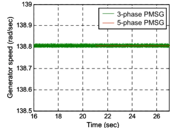
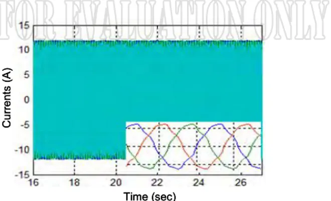
The three- and five-phase PMSG-based MCT control performances in healthy conditions are shown in Figs. 3 to 7, respectively illustrating the rotor speed, the generated power, the mechanical torque, and the PMSG currents. These simulation results lead to the following main conclusions:
– The five-phase PMSG-based MCT generated power is very smooth (Fig. 4).
– The peak-to-peak torque ripples are significantly reduced in the five-phase PMSG (Fig. 5).
It is therefore obvious that a multiphase generator is more appropriate for MCTs normal operation than a classical three-phase generator. 16 18 20 22 24 26 138.5 138.6 138.7 138.8 138.9 139 3phase PMG 5 phase PMG Time (sec) G e n er a to r sp e ed ( ra d/ se c) 3-phase PMSG5-phase PMSG 16 18 20 22 24 26 138.5 138.6 138.7 138.8 138.9 139 3phase PMG 5 phase PMG Time (sec) G e n er a to r sp e ed ( ra d/ se c) 3-phase PMSG5-phase PMSG
Fig. 3. Marine current turbine generator speed under normal conditions.
16 18 20 22 24 26 1000 1050 1100 1150 1200 1250 3 phase PMG 5 phase PMG Time (sec) P ow er ( W ) 3-phase PMSG 5-phase PMSG 16 18 20 22 24 26 1000 1050 1100 1150 1200 1250 3 phase PMG 5 phase PMG Time (sec) P ow er ( W ) 3-phase PMSG 5-phase PMSG 3-phase PMSG 5-phase PMSG
Fig. 4. Marine current turbine power under normal conditions.
Time (sec) T or qu e ( W ) 16 18 20 22 24 26 7.8 7.9 8 8.1 3 phase PMG 5 phasePMG 3-phase PMSG 5-phase PMSG Time (sec) T or qu e ( W ) 16 18 20 22 24 26 7.8 7.9 8 8.1 3 phase PMG 5 phasePMG 3-phase PMSG 5-phase PMSG 3-phase PMSG 5-phase PMSG
Fig. 5. Marine current turbine mechanical torque under normal conditions.
Time (sec) C ur re nt s (A ) Time (sec) C ur re nt s (A )
Time (sec) C u rr en ts (A ) Time (sec) C u rr en ts (A )
Fig. 7. Three-phase PMSG under normal conditions.
B. Operation under Open-Circuit Fault Conditions
The two generators performances are now evaluated under an open-circuit in the first phase. In this case, a reference current is now on-line determined under faulty conditions to achieve a constant and smooth torque, equals to the one under normal conditions, and leading to minimum copper losses.
Simulation results are shown in Figs. 8 to 11, the generated power, the mechanical torque, and the PMSG currents. These simulation results lead to the following main conclusions:
– The five-phase PMSG-based MCT generated power is still quiet smooth even in faulty conditions (Fig. 8).
Time (sec) P ow er ( W ) 7.5 8 8.5 9 9.5 0 500 1000 1500 3 phase PMG 5 phase PMG 3-phase PMSG 5-phase PMSG Time (sec) P ow er ( W ) 7.5 8 8.5 9 9.5 0 500 1000 1500 3 phase PMG 5 phase PMG 3-phase PMSG 5-phase PMSG 3-phase PMSG 5-phase PMSG
Fig. 8. Marine current turbine power under open-circuit fault conditions.
T or qu e (W ) 7.5 8 8.5 9 9.5 2 4 6 8 10 12 14 3 phasePMG 5 phase PMG Time (sec) 3-phase PMSG 5-phase PMSG T or qu e (W ) 7.5 8 8.5 9 9.5 2 4 6 8 10 12 14 3 phasePMG 5 phase PMG Time (sec) 3-phase PMSG 5-phase PMSG 3-phase PMSG 5-phase PMSG
Fig. 9. Marine current turbine torque under open-circuit fault conditions.
Time (sec) C ur re nt s (A ) Time (sec) C ur re nt s (A )
Fig. 10. Five-phase PMGS currents under open-circuit fault conditions.
Time (sec) C ur re nt s (A ) Time (sec) C ur re nt s (A )
Fig. 11. Three-phase PMGS currents under open-circuit fault conditions.
– The torque ripples are significantly reduced in the five-phase PMSG thanks to the proposed procedures (Fig. 9) [15]. Indeed, the torque remains quiet smooth. Therefore, no extra stresses are induced in the MCT torque.
– The three-phase PMSG currents increase is quiet huge compared to the five-phase one.
The analysis of the above performances under faulty conditions confirms the fact that a multiphase generator is clearly a candidate of choice for a marine current turbine.
V.CONCLUSION
This paper dealt with a comparative study of three- and five-phase PMSG within the context of a marine current turbine application in normal and faulty conditions. The PMSG control strategy was based on a high-order sliding mode approach using a super twisting algorithm. In faulty conditions, a reference current is on-line determined to achieve a constant and smooth torque, equals to the one under normal conditions, and leading to minimum copper losses.
The obtained results clearly show that, even in normal operation, a multiphase generator is clearly a candidate of choice for marine current turbine applications, in comparison to a classical three-phase generator.
REFERENCES
[1] M.S. Güney et al., “Hydrokinetic energy conversion systems: A technology status review,” Renewable and Sustainable Energy Reviews, vol. 14, n°9, pp. 2996-3004, December 2010.
[2] M.J. Khan et al., “Hydrokinetic energy conversion systems and assessment of horizontal and vertical axis turbines for river and tidal applications: A technology status review,” Applied Energy, vol. 86, n° 10, pp. 1823-1835, October 2009.
[3] S. Benelghali et al., “Experimental validation of a marine current turbine simulator: Application to a PMSG-based system second-order sliding mode control,” IEEE Trans. Industrial Electronics, vol. 58, n°1, pp. 118-126, January 2011.
[4] Y. Li et al., “Modeling the operation and maintenance costs of a large scale tidal current turbine farm,” in Proceedings of the IEEE OCEANS’06, Boston (USA), September 2006.
[5] Amirat et al., “A brief status on condition monitoring and fault diagnosis in wind energy conversion systems,” Renewable & Sustainable Energy Reviews, vol. 3, n°9, pp. 2629-2636, December 2009.
[6] E. Levi et al., “Multiphase induction motor drives - a technology status review,” IET Electric Power Applications, vol. 1, n°4, pp. 489-516, July 2007.
[7] F. Mekri et al., “A fault-tolerant multiphase permanent magnet generator for marine current turbine applications,” in Proceedings of the IEEE ISIE 2011, Gdansk (Poland), June 2011.
[8] S. Dwari et al., “Fault-tolerant control of five-phase permanent-magnet motors with trapezoidal back EMF,” IEEE Trans. Industrial Electronics, vol. 58, n°2, pp. 476-485, February 2011.
[9] F. Mekri et al., “High order sliding mode optimal current control of 5-phase under open circuited 5-phase fault conditions,” in Proceedings of the IEEE VPPC 2010, Lille (France), September 2011.
[10] F. Locment et al., “Vectorial approach based control of a seven-phase axial flux machine designed for fault operation,” IEEE Trans. Industrial Electronics, vol. 55, n°10, pp. 3682-3691, October 2008. [11] L. Parsa et al., “Five-phase permanent–magnet motor drives,” IEEE
Trans. Industry Applications, vol. 41, n°1, pp. 30-37, January-February 2005.
[12] B. Beltran et al., “Sliding mode power control of variable-speed wind energy conversion systems,” IEEE Trans. Energy Conversion, vol. 23, n°2, pp. 551-558, June 2008.
[13] B. Beltran et al., “High-order sliding mode control of variable speed wind turbines,” IEEE Trans. Industrial Electronics, vol. 56, n°9, pp. 3314-3321, September 2009.
[14] X. Kestelyn et al., “Generation of on line optimal current references for multi-phase permanent magnet machines with open circuit phases,” in Proceedings of the IEEE IEMDC’09, Miami (USA), pp 689-694, May 2009.
[15] N.E.A.M Hassanain et al., “steady-state performance assessment of three- and five-phase permanent magnet generators connected to a diode bridge rectifier under open-circuit faults,” IET Renewable Power Generation, vol.4, n°5, pp 420-427, September 2010.