HAL Id: hal-02891884
https://hal.archives-ouvertes.fr/hal-02891884
Submitted on 7 Jul 2020
HAL is a multi-disciplinary open access
archive for the deposit and dissemination of
sci-entific research documents, whether they are
pub-lished or not. The documents may come from
teaching and research institutions in France or
abroad, or from public or private research centers.
L’archive ouverte pluridisciplinaire HAL, est
destinée au dépôt et à la diffusion de documents
scientifiques de niveau recherche, publiés ou non,
émanant des établissements d’enseignement et de
recherche français ou étrangers, des laboratoires
publics ou privés.
WAAT: a Workstation AR Authoring Tool for Industry
4.0
Pierre Bégout, Thierry Duval, Sébastien Kubicki, Bertrand Charbonnier,
Emmanuel Bricard
To cite this version:
Pierre Bégout, Thierry Duval, Sébastien Kubicki, Bertrand Charbonnier, Emmanuel Bricard. WAAT:
a Workstation AR Authoring Tool for Industry 4.0. SALENTO AVR 2020, Sep 2020, Lecce, Italy.
�hal-02891884�
Industry 4.0
Pierre B´egout1,2,4, Thierry Duval2,3, S´ebastien Kubicki3,4, Bertrand Charbonnier2,3, and Emmanuel Bricard1
1
elm.leblanc, Drancy, France
2
IMT Atlantique, Brest, France
3 ENIB, Brest, France 4
Lab-STICC, UMR CNRS 6285
Figure 1. Operator on an assembly line using AR guidance to select components
Abstract In this paper, we present WAAT, an AR authoring tool dedi-cated to industrial environments. The interest of such a tool in an indus-trial context is to allow non-expert users to quickly create and dynami-cally modify 3D models of workstations, and also test the AR guidance placement. WAAT makes on-site authoring possible, which should really help to have an accurate 3D representation of assembly lines. The verifi-cation of AR guidance should also be very useful to make sure everything is visible and doesn’t interfere with technical tasks. We deployed WAAT in an assembly line of an elm.leblanc/Bosch boiler factory to assess its features in an ecological context. We also made a comparison to another AR authoring tool to better estimate its advantages.
Keywords: 3D authoring · AR Authoring tool · Virtual Reality · Aug-mented Reality · Mixed Reality · AR Training · AR guidance · Virtual environment · Industry 4.0 · Human-computer interaction · 3D interac-tion
1
Introduction
In a context of constant industrial evolution and a need of more industrial agility to answer the increasingly unpredictable customer requests, having well trained assembly line operators is extremely important. This operator training problem-atic is well known by manufacturers such as elm.leblanc, a boiler manufacturer for which this training problem is very important during each winter, when boiler orders rise a lot, as many temporary workers must be hired for a few months. The training of these new operators is an important process that involves a lot of time and human resources. For instance, one experimented operator is dedicated to the training of one new operator. During this time, the production lines out-put is not optimal because of the learning curve of the new operators as well as the attention they require from permanent staff decreasing the overall capacity. One solution to this training issue is the use of AR in the factory (cf. Fig-ure 1), to train new operators directly on the assembly line with less supervision from experimented operator. This tool could also be used by an experimented operator to train on a new position of the assembly line or a different assembly line.
Indeed, in the industrial context, AR can be used in many different ways . It can be used to make expert remote guidance, create new products using collab-orative engineering methods, or realize digital inspection of new prototypes [6]. AR is also used to test the ergonomics of the workstations and the reachability of some equipment [2]. Error and default detection using AR are possible and very useful in Airbus factories [1]. These different uses have a lot of potential, but the most interesting feature of AR in our case and the most used is the assembly as-sistance, for training purpose [19, 1]. Actually, assembly tasks training using AR has been researched for a long time, with the comparison of paper instructions sheets with VR and AR instructions, showing that AR instructions were the most efficient [3]. More recently, new ways of using AR for assembly training are researched, by combining AR and other tools. It can be an intelligent tutoring system for error detection [23] or data from the factory [17, 4].
These AR environments are created with AR authoring tools, and most of them are dedicated to 3D CAD experts or 3D AR experts. So, even if the end-users can participate to the modelling of the AR environment during its user-centred design with such authoring tools, they cannot use them to evolve the AR representation according to the real environment changes.
This is why we make the assumption that to be efficient and to provide feedback on the operator in training, such authoring tools should be dedicated to line managers. It would permit the users with the real knowledge of the assembly line to model its different elements. These elements could be, for instance, 3D models or anchors1.
In our industrial context, which can occur quite often for factories, the 3D models of the parts of the assembly line are not available or could change dy-namically according to the needs of the production. This is why we cannot use a
1
classical 3D CAD tool to manage the placement of the augmentation relatively to the parts of the assembly line and we need an authoring tool to facilitate the configuration of the AR training tool.
Our contribution is to improve AR authoring by proposing a tool allowing line managers, who are not familiar neither with AR technology nor 3D CAD tools, to quickly create a 3D representation of the assembly line, by placing and manipulating 3D elements easily without the need of long training time to be efficient with AR technology.
The remaining of this paper is organized as follows: in section 2 we explain the industrial constraints for the use of this authoring tool. Section 3 contains the related work, justifying the choices made in section 4 which describes WAAT, our authoring tool. Section 5 describes the comparison between WAAT and Microsoft Guides on an authoring task. Finally, section 6 concludes this paper and discusses about future developments.
2
Industrial context
In an industrial context, we have a lot of constraints related to the nature of the workstations and the way boiler assembling is done. We have many problematic to take into account in order to make an authoring tool that allows line managers to quickly and easily create a 3D representation of the assembly line.
2.1 Time management
When working on an assembly line, every gesture is thought to accomplish the technical action in the smallest amount of time possible. Every workstation is thought to accomplish a certain number of technical tasks, the placement of each equipment is well thought. Therefore the authoring tool should help gaining time in the factory by quickly configuring the training tool. The final user of this authoring tool should be able to perform the authoring task quickly, otherwise the tool won’t be used.
2.2 Managing evolution
The elm.leblanc company assembly lines are manageable and can be changed during the day to correspond with the current boiler model. Each workstation can be rearranged (some parts are on wheels to be easily movable). Some tasks can pass from a workstation to another when changing the boiler model currently assembled on the line.
This leads to the need of regular updates of the 3D model of the assembly line to correspond to the state of the real one and/or to new boilers models. The most suitable user to perform these updates is the line manager, who knows the assembly line state and each workstation very well.
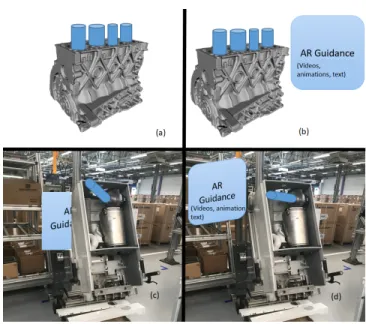
Figure 2. Needed features of the authoring tool. (a) 3D models placement with a motor. (b) AR guidance placement on the motor. (c) AR checking of 3D models and AR guidance on a real boiler. (d) AR validation of the placement on a real boiler
2.3 Main features
Knowing these requirements, we have several uses for our authoring tool. First, the authoring tool must allow fast and easy placement of 3D models of the work-station (cf. Figure 2a). The AR guidance could consist of an information panel containing text, videos, pictures, or it could also be highlights of 3D models. This AR guidance must also be placed easily (cf. Figure 2b). The AR part of the tool must allow the user to compare the 3D models and the real objects (cf. Figure 2c), and to move or resize the 3D objects to match the real scene and the objects, and also to make sure the operator guidance panel is visible (cf. Fig-ure 2d). The next section presents the state of the art about 3D authoring tools that we could use to meet all our requirements.
2.4 Tool evaluation criteria
Knowing our constraints and our context, we defined criteria to evaluate the different tools we studied. First, the tool must allow the placement of 3D models, and also the placement of AR guidance (3D animation, text, video) to check its placement and its visibility. As seen previously, the workstations can change quite often so we need to be able to do live edit while in AR. The industrial context prevents us to put tracking markers (detailed in section 3.2) everywhere to track the workstation elements, so we need to use only one marker for the whole workstation. The training required to use the authoring tool must be fast and
simple. The tool’s interface must be simple, a GUI authoring is preferable. Our final users are the line managers and experimented operators, so the authoring tool needs to be easy to use, and the AR part must be usable hands free to enable users to perform the technical tasks (head mounted display are probably the best solution to do that).
3
Related work
3.1 3D Authoring tools
3D models of components and workstations are widely used in the industry. Most of the time they are used to create the full product, change the layout of the factory, test the ergonomics of the workstations [2]. To design these 3D models, many tools are available since the 70’s. Some of the most used tools to model industrial component are SolidWorks2, Inventor3, CATIA4, Pro/ENGINEER5 and AutoCAD6. These tools offer precise modeling features. The problem with these CAD (Computer Aided Design) tools is that their learning curve is very steep and require dozens of hours to properly use them [14]. It is also difficult to export files to AR engines like Unreal7or Unity8without the use of an other software. Usually, the exported object are opened in a DCC (Digital Content Creation) tool (Blender9 for example) to be converted in a suitable format for AR engines.
Other digital content creation tools, such as 3dsMax10, Maya11, Blender, can be used to model our workstation, but just as the previous CAD softwares seen previously, their interface is very complicated, and the learning time is very high. They offer lots of options to create very precise 3D models. SketchUp12, another DCC tool, is easier to learn since it is based on line drawing but the 3D models obtained this way are less accurate than with the other tools [20].
These 3D modeling tools are great when accurate 3D models are required, but they target professional designers who can spend time to learn a new tool and realize accurate 3D models of industrial components and workstations. In our case, we don’t need such accurate 3D models. Indeed we only need to represent the components of the workstation and their position to the AR guidance tool.
2 https://www.solidworks.com/ 3 https://www.autodesk.com/products/inventor/overview 4 https://www.3ds.com/products-services/catia/ 5 https://www.ptc.com/en/products/cad/pro-engineer 6 https://www.autodesk.com/products/autocad/overview 7 https://www.unrealengine.com/en-US/ 8 https://unity.com/ 9 https://www.blender.org/ 10https://www.autodesk.com/products/3ds-max/overview 11 https://www.autodesk.com/products/maya/overview 12 https://www.sketchup.com/
3.2 AR Authoring
To be able to use AR authoring tools in our assembly lines, we have to know where to locate the 3D models in the space, to place them at the right position, and which graphical assets to use. To achieve that goal, several tracking tech-niques are used, and several recommendations exists. These are detailed in the next subsection.
Graphic elements To use AR in an industrial context, we have to adapt our graphical assets to be easy to understand, create and render, and avoid occlu-sion [7]. To achieve that goal, it is better to use symbols and simple models [22] to guide the user and represent instructions. Text can be used but has to be simplified [8] and write in a billboard to have contrast between the text and the background.
Tracking methods Tracking is a fundamental issue when using AR. Accu-rate and stable tracking techniques are important for using AR in an indus-trial environment. Most of the time, markers are used to locate the real ob-jects and help positioning 3D obob-jects. The capture of the marker is made by image recognition. After recognition, the 3D object linked with the marker ap-pears [25, 18, 23, 24, 12, 21, 10]. Markers can be pictures, QR code, colored paper, any kind of 2D unique-looking object. This technique is easy to imple-ment and useful in an environimple-ment that can change depending on the assembly task such as our assembly line. An other tracking technique uses object recog-nition by comparing a 3D model of the object to the real object captured by the camera [5]. This technique requires precise 3D models of our objects and is useful in a static environment, which is not the case with our assembly line.
AR Authoring tools With the emergence of AR, many tools have appeared to build AR applications such as ARToolkit [13] that provides a marker-based registration using computer vision. ARToolKit and its variations all require the user to have C/C++ skills. More recently, Vuforia13a software development kit, provides computer vision technology to recognize and track planar images and 3D objects in real time. To use Vuforia, C# skills are necessary. This is the main problem with creating AR content. Most of the time low level AR libraries are used, requiring programming skills from the user.
The need for High level AR authoring tools for non-programmers is im-portant. The earlier frameworks were often a plug-in of an other software, like DART [16], a plug-in for Adobe Director14(not supported anymore). DART was supporting the 3D editing part of the software with visual programming, such as dragging a 3D object in a scene and adding behavioral scripts to the object. Another GUI-based visual AR authoring tool, AMIRE [11] allows the user to
13
https://developer.vuforia.com/
14
describe interactions between objects with visual representations, which can be-come complex. An other approach with a more rigid framework was APRIL [15] based on XML descriptions. APRIL is a plug-in of their own platform containing XML parser. Using XML can be quite difficult for a user with no programming skills at all.
More recently, 3D GUI-based authoring tools have been studied. In ACARS [25] the authoring part is realized on desktop using a 3D model of the equipment. The maintenance technician can do on-site authoring using a tangible object to change the information’s position. The authoring in SUGAR [10] is also real-ized on desktop. The maintenance expert can place AR information around the equipment using depth map of the factory. The authoring is also made by an expert in ARAUM [5], he gives information to the authoring tool about the pro-cedures to perform, which will place automatically the AR content around the equipment using spatial, time and user context. Some authoring tools include the final user in the authoring process. In ARTA [8], an experienced worker is recorded performing a task using eye-tracking and a camera, but he also has to learn how to use Unity3D to split the recording in different steps. The final user can also intervene to verify the quality of the modeling in AR [9], to add details in the instructions or edit the models, but the original modeling is done by an engineer. The target devices for these authoring tools are HMD (Head Mounted Display) devices, but a mobile platform (tablet or phone) can also be a good alternative. Using the VEDILS framework [18] allows any user to create AR content for mobile using a desktop application. It uses visual programming and behavioral blocks to add interactions to the 3D objects, but it requires knowledge in algorithmic to be used properly.
Using mobiles to visualize AR content leads to research on mobile AR author-ing tools, reducauthor-ing the material needed for the authorauthor-ing task, allowauthor-ing in-situ authoring, which can be really interesting in some situations where we don’t have access to a computer. HARATIO [21] allows the user to add 3D objects from a library in a scene, including behavior scripts. All actions are made with a radial menu. We can see limitations with mobile authoring tools like in [12] or [24]. In the first one, the user interacts with the 3D object on the touch screen, whereas in the second one the interactions are done directly with the markers which can be combined. With these tools we can only associate one marker with one 3D object.
It seems that authoring tasks made using desktop applications are often realized by an expert on the industrial procedure or a designer while we need our tool to be usable by line managers. It also seems that most authoring tools don’t allow users to directly edit the content while in AR to better match the real objects. Mobile authoring can be interesting in our case but the interaction limitations and the marker/3D object limit is a problem because we will have multiple 3D objects per workstation.
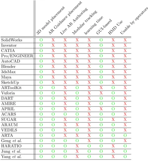
Table 1. Table summarizing the main features of 3D authoring tools suited for AR authoring. 3D mo del placemen t AR Guid ance placemen t Liv eAR Auth oring Mo dular trac king learning time GUI-basedHMD Use Usable by operators SolidWorks O X X X X O X X Inventor O X X X X O X X CATIA O X X X X O X X Pro/ENGINEER O X X X X O X X AutoCAD O X X X X O X X Blender O X X X X O X X 3dsMax O X X X X O X X Maya O X X X X O X X SketchUp O X X X X O X X ARToolKit O O X O X X O X Vuforia O O X O X X O X DART O O X O X O O X AMIRE O O X O X O O X APRIL O O X O X X O X ACARS O O O O X O O X SUGAR O O X O X O X X ARAUM O O X X X O O X VEDILS O O X O X O O X ARTA O O X X X O O O Geng et al. O O O O X O O X HARATIO O O O X O O X O Jung et al. O O O X O O X O Yang et al. O O O X O O X O
4
WAAT (Workstation AR Authoring Tool)
To meet all the requirements presented in section 2 and summarized in Table 1, we propose WAAT: an authoring tool designed to allow users to create 3D scenes of workstations by placing 3D objects representing the workstation. The originality of WAAT is that it makes it possible for the user to compare the 3D model with the real workstation. The authoring task in WAAT is easy to perform by production staff, only need a few 3D models, and does not require any engineer or designer.
4.1 System overview
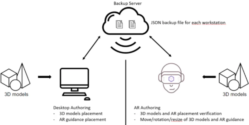
WAAT is composed of two modules, a desktop 3D authoring module and an AR authoring module, as illustrated Figure 3. The desktop authoring module (see Figure 4) is used to create the 3D scene whereas the AR authoring module is used to modify and validate the placement and/or size of the 3D models. The two modules are connected by the server, with a JSON file for each scene allowing the user to modify the scene either on desktop or AR.
Figure 3. WAAT system overview
WAAT is developed with Unity using Vuforia for the marker tracking in the AR module. The AR hardware currently used is the Microsoft Hololens 215.
To deploy WAAT on another AR device such as the Magic Leap16 we would just have to add to our system the Magic Leap extension of the SDK (Software Development Kit) we currently use.
4.2 3D authoring of the assembly line
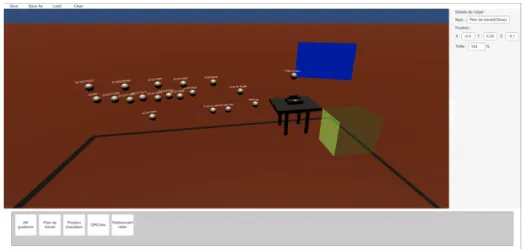
The authoring task on the desktop application is done with simple interactions using a mouse and a keyboard. To select which object the user wants to add, he just has to choose the object in the bottom interface (cf. Figure 4) and define its position in the scene (we get the 3D objects from any 3D modelling or CAD tool). He can then move the objects to place them more precisely and change some of their properties (e.g., name, scale, . . . ). We chose drag and drop as the interaction method but it is not the only one available (i.e., keyboard or a graphic overlay for the axis and rotation), and testing will help to choose the
15
https://www.microsoft.com/en-us/hololens
16
best suited one. Then the user can save the scene he created or load a scene previously created.
Figure 4. WAAT desktop module
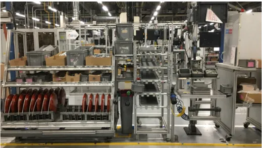
We tested WAAT on a workstation from the factory (cf. Figure 5). We used 3D models to represent the workstation and the placement of the boiler. We represented the boxes where the parts to assemble are kept and the tools to use with ”spatial anchors”, a 3D object allowing the AR training tool to know the position of the different part to pick (see Figure 8). We also placed the panel used to display AR assembly guidance.
We conceived WAAT to also be usable in an immersive mode, but we focused on the main features of the tool and our users want to use it in non-immersive mode for the moment.
4.3 Using AR to check the 3D modeling
To make sure the 3D model of the assembly line is on par with the real assembly line, the user will use the AR part of the tool and compare the position, rotation, size of the 3D objects with their corresponding real object.
If it is not on par with the real objects (as illustrated in Figure 6), the user can move the 3D objects by grabbing them and placing them at the correct position. Each 3D object refers to a real object and must be placed, rotated and scaled as its real counterpart to allow the AR guidance system to be well configured (as illustrated in Figure 9). The AR guidance system will use the position of the 3D objects to tell the operator where to grab or place technical parts.
After finishing all his modifications, the user can save his work, which updates the 3D model of the assembly line in the WAAT system. He can now load another scene to check the 3D modeling.
Figure 5. The workstation we want to model
Figure 6. Bad placement and size of the 3D models
4.4 WAAT and AR guidance
WAAT is also used to place the marker position for further AR guidance of the operators. Each scene is associated to a marker allowing the system to load the correct objects related to a workstation. The 3D objects in WAAT are then used for the training or as anchors for the AR guidance system.
Placing AR markers in the model of the assembly line After the 3D modeling of the assembly line, the final step is to place the markers positions in the virtual scenes. This virtual marker is used to show the user in AR the position where he is supposed to place the real marker to use the system. It is placed in the same way than any other 3D object.
Placing AR markers in the real assembly line To be able to test the AR guidance (and to use it during the operator formation) the user has to place real markers at the same place as the ”virtual” markers in the real assembly line. For every workstation, a specific marker is placed in a specific position. If the real marker is not at the same position as the virtual one, as illustrated Figure 7, all the 3D objects will be misplaced compared to the real objects. If the position of the virtual marker is too difficult to use in the assembly line, the user can move it to match the correct position and obtain the situation illustrated in Figure 8.
Figure 7. Bad marker placement on the real object
AR Checking of the AR guidance The AR scene is also used to verify the positioning of the ”operator guidance”: the panels where the training instructions will be shown. The user can move these panels to make sure the instructions are visible and that there is no occlusion or other problems. The user will also check the positioning of all markers and objects and move them if needed since they will also be used by the AR guidance system.
Figure 8. Good placement of the AR Guidance
Figure 9. Good placement of the 3D models
Here again, after finishing all his modifications, the user can save his work, this will update the assembly line model globally, and more precisely, the markers positions and AR guidance panels positions.
5
Comparison with Microsoft Dynamics 365 Guides
We compared the use of our tool WAAT with the solution from Microsoft17. This solution is similar to ours, it is separated in two modules: the desktop module and the AR module. The desktop module is the place where the user creates the instructions and add the 3D models tied with these instructions. The difference with WAAT is that there is no placement of the 3D models with Microsoft Dynamics 365 Guides. The AR module is used for the placement of the 3D models in the real environment and to create the AR assistance (i.e., arrows showing what to do at each instruction, where to place the element). The tracking is made with a QR code.
We compared the authoring time to place the 3D models of the workstation at the right position between WAAT and Microsoft Guides. We evaluated the total authoring time (desktop + AR), with the same number of 3D models to place on the same workstation.
Table 2. Table summarizing the time (minutes) for the authoring of a workstation using WAAT or Guides.
Tool Desktop AR Total WAAT 6’30” 1’50” 8’20” Guides 3’19” 5’10” 8’29”
The desktop authoring is faster with Guides, since there is no placement of the 3D objects in a virtual world. The 3D models are linked to a task and their characteristics can’t be changed (position, name, scale).
For the AR authoring, our tool is much faster because the 3D models are already placed almost at the right position. The movement to achieve the right positioning is minimal. In Guides, however, the user has to get the 3D models in the instructions panel, requiring a lot of movement, and taking a lot of time. As summarized in Table 2, we can see that WAAT is slightly faster than Guides on the environment authoring task. To improve our tool and reduce the authoring time, we have to improve the desktop authoring, and more precisely the placement of the 3D models. One of the considered solution is workstation templates placing the anchors automatically with only the references in entry. However in WAAT, knowing the names and positions of the 3D models and anchors allows the AR assistance creation tool to generate automatically the placement instructions by collision detection.
More testing is required, in which we will evaluate the authoring time, the number of error, the accuracy and fidelity. We will also evaluate the usability with the System Usability Scale, and a workload test with the Nasa TLX.
17
6
Conclusion
In this paper, we have presented WAAT, a 3D authoring tool allowing untrained users to create 3D models of the assembly line in a boiler factory. WAAT allows fast creation and AR comparison of the virtual and the real model. In case of a mismatch between both virtual and real models, the user can easily and quickly move the 3D virtual components to match the components of the real worksta-tion. He can test the AR guidance used to train assembly line operators to make sure that everything is fully visible and doesn’t interfere with the realization of the technical tasks.
Improving desktop authoring will be an important part of our future work to reduce the time spent on the desktop part. First, to adapt the interactions used to move/rotate/resize the 3D objects to our users, adding accessories such as a 3D controller will be explored. We will also test new AR systems to test their usability and native interactions to see if we can use them, or if we can adapt them to our users. Second, we have to make other tests with the line managers from the factory to enhance the usability and the intuitiveness of WAAT. Last, using 3D models of the workstations will also allow us to test the ergonomics of new workstations during the creation process with the use of a posture capture outfit.
Finally, the immersive mode of WAAT will allow us to visualize the aug-mented environment and test the placement of the operator guidance, even if it’s not the focus right now. We will be able to simulate the AR test of the scenes without the need to be in the factory all the time.
Acknowledgements
This work is possible thanks to the workers of the Drancy elm.leblanc factory and of Saint-Th´egonnec elm.leblanc factory for exchanging with us on the prob-lematic of their work and helping us to better understand their needs in 3D modeling and AR guidance.
[1] Barbosa, G.F., Frigo, M.A., Da Silva, E.C.C., Barbosa, G.F.: Augmented Reality in Aerospace Manufacturing: A Review. Journal of Industrial and Intelligent Information Vol. 4(No. 2) (2016)
[2] Berg, L.P., Vance, J.M.: Industry use of virtual reality in product design and manufacturing: a survey. Virtual Reality 21(1), 1–17 (mar 2017) [3] Boud, A.C., Haniff, D.J., Baber, C., Steiner, S.J.: Virtual reality and
aug-mented reality as a training tool for assembly tasks. In: Proceedings of the International Conference on Information Visualisation. vol. 1999-Janua, pp. 32–36. Institute of Electrical and Electronics Engineers Inc. (1999)
[4] Danielsson, O., Syberfeldt, A., Holm, M., Wang, L.: Operators perspective on augmented reality as a support tool in engine assembly. In: Procedia CIRP. vol. 72, pp. 45–50. Elsevier B.V. (2018)
[5] Erkoyuncu, J.A., del Amo, I.F., Dalle Mura, M., Roy, R., Dini, G.: Im-proving efficiency of industrial maintenance with context aware adaptive authoring in augmented reality. CIRP Annals - Manufacturing Technology 66(1), 465–468 (2017)
[6] Fraga-Lamas, P., Fernandez-Carames, T.M., Blanco-Novoa, O., Vilar-Montesinos, M.A.: A Review on Industrial Augmented Reality Systems for the Industry 4.0 Shipyard. IEEE Access 6, 13358–13375 (2018)
[7] Gattullo, M., Scurati, G.W., Evangelista, A., Ferrise, F., Fiorentino, M., Uva, A.E.: Informing the Use of Visual Assets in Industrial Augmented Reality. In: Lecture Notes in Mechanical Engineering. pp. 106–117. Springer (sep 2020)
[8] Gattullo, M., Scurati, G.W., Fiorentino, M., Uva, A.E., Ferrise, F., Borde-goni, M.: Towards augmented reality manuals for industry 4.0: A method-ology. Robotics and Computer-Integrated Manufacturing 56, 276–286 (apr 2019)
[9] Geng, J., Song, X., Pan, Y., Tang, J., Liu, Y., Zhao, D., Ma, Y.: A systematic design method of adaptive augmented reality work instruction for complex industrial operations. Computers in Industry 119, 103229 (aug 2020) [10] Gimeno, J., Morillo, P., Ordu˜na, J., Fern´andez, M.: A new AR authoring
tool using depth maps for industrial procedures. Computers in Industry 64(9), 1263–1271 (dec 2013)
[11] Grimm, P., Haller, M., Paelke, V., Reinhold, S., Reimann, C., Zauner, R.: AMIRE-authoring mixed reality. In: ART 2002 - 1st IEEE International Augmented Reality Toolkit Workshop, Proceedings. Institute of Electrical and Electronics Engineers Inc. (2002)
[12] Jung, J., Hong, J., Park, S., Yang, H.S.: Smartphone as an augmented reality authoring tool via multi-touch based 3D interaction method. In: Proceedings of the 11th ACM SIGGRAPH International Conference on Virtual-Reality Continuum and its Applications in Industry - VRCAI ’12. p. 17. ACM Press, New York, New York, USA (2012)
[13] Kato, Billinghurst: Marker Tracking and HMD Calibration for a Video-based Augmented Reality Conferencing System. Proceedings 2nd IEEE and ACM International Workshop on Augmented Reality (IWAR’99) (1999) [14] Kostic, Z.: Comparative Study of CAD Software, Web3D Technologies and
Existing Solutions to Support Distance-Learning Students of Engineering Profile. International Journal of Computer Science Issues 9(4), 181–187 (2012)
[15] Ledermann, F., Schmalstieg, D.: APRIL: a high-level framework for creating augmented reality presentations. In: IEEE Proceedings. VR 2005. Virtual Reality, 2005. pp. 187–194. IEEE (2005)
[16] MacIntyre, B., Gandy, M., Dow, S., Bolter, J.D.: DART. In: Proceedings of the 17th annual ACM symposium on User interface software and technology - UIST ’04. p. 197. ACM Press, New York, New York, USA (2004)
[17] Makris, S., Karagiannis, P., Koukas, S., Matthaiakis, A.S.: Augmented re-ality system for operator support in human–robot collaborative assembly. CIRP Annals - Manufacturing Technology 65(1), 61–64 (2016)
[18] Mota, J.M., Ruiz-Rube, I., Dodero, J.M., Arnedillo-S´anchez, I.: Augmented reality mobile app development for all. Computers and Electrical Engineer-ing 65, 250–260 (jan 2018)
[19] Paelke, V.: Augmented reality in the smart factory: Supporting workers in an industry 4.0. environment. In: Proceedings of the 2014 IEEE Emerging Technology and Factory Automation (ETFA). pp. 1–4. IEEE (sep 2014) [20] Parisi, T.: Programming 3D Applications with HTML5 and WebGL: 3D
Animation and Visualization for Web Pages. O’reilly m edn. (2014) [21] Sambrooks, L., Wilkinson, B.: Designing HARATIO: A novice AR authoring
tool. In: Proceedings of the 28th Australian Computer-Human Interaction Conference, OzCHI 2016 (2016)
[22] Scurati, G.W., Gattullo, M., Fiorentino, M., Ferrise, F., Bordegoni, M., Uva, A.E.: Converting maintenance actions into standard symbols for Augmented Reality applications in Industry 4.0. Computers in Industry 98, 68–79 (jun 2018)
[23] Westerfield, G., Mitrovic, A., Billinghurst, M.: Intelligent augmented real-ity training for motherboard assembly. International Journal of Artificial Intelligence in Education 25(1), 157–172 (2015)
[24] Yang, Y., Shim, J., Chae, S., Han, T.D.: Mobile Augmented Reality Au-thoring Tool. In: Proceedings - 2016 IEEE 10th International Conference on Semantic Computing, ICSC 2016. pp. 358–361. Institute of Electrical and Electronics Engineers Inc. (mar 2016)
[25] Zhu, J., Ong, S.K., Nee, A.Y.: An authorable context-aware augmented reality system to assist the maintenance technicians. International Journal of Advanced Manufacturing Technology 66(9-12), 1699–1714 (2013)