HAL Id: hal-02163678
https://hal-univ-rennes1.archives-ouvertes.fr/hal-02163678
Submitted on 24 Jun 2019
HAL is a multi-disciplinary open access archive for the deposit and dissemination of sci-entific research documents, whether they are pub-lished or not. The documents may come from teaching and research institutions in France or abroad, or from public or private research centers.
L’archive ouverte pluridisciplinaire HAL, est destinée au dépôt et à la diffusion de documents scientifiques de niveau recherche, publiés ou non, émanant des établissements d’enseignement et de recherche français ou étrangers, des laboratoires publics ou privés.
Hongzhi Yang, Marc Vallet, Haiyang Zhang, Changming Zhao, Marc Brunel
To cite this version:
Hongzhi Yang, Marc Vallet, Haiyang Zhang, Changming Zhao, Marc Brunel. Pulse doublets generated by a frequency-shifting loop containing an electro-optic amplitude modulator. Optics Express, Optical Society of America - OSA Publishing, 2019, 27 (13), pp.18766-18775. �10.1364/OE.27.018766�. �hal-02163678�
Pulse doublets generated by a
frequency-shifting loop containing an electro-optic
amplitude modulator
H
ONGZHIY
ANG,
1,2M
ARCV
ALLET,
2H
AIYANGZ
HANG,
1C
HANGMINGZ
HAO,
1 ANDM
ARCB
RUNEL2,*1School of Optics and Photonics, Beijing Institute of Technology, Beijing, China 2Univ Rennes, CNRS, Institut FOTON – UMR 6082, 35000 Rennes, France
Abstract: We investigate theoretically and experimentally an all-fibered frequency-shifting
loop which includes an electro-optic amplitude modulator (EOM) and an optical amplifier, and is seeded by a continuous-wave laser. At variance with frequency-shifted feedback lasers, or Talbot lasers, that contain an acousto-optic frequency shifter, the EOM creates at each round-trip two side-bands that recirculate inside the loop. Benefiting from the high modulation frequency of the EOM, a wide optical frequency comb up to 40 GHz is generated. We demonstrate an original double-pulse regime when the loop length is a multiple of the RF modulation wavelength applied to the modulator. The inter-pulse interval is governed by both the bias voltage and modulation depth of the EOM. Besides, some typical waveforms such as saw-tooth and rectangle are experimentally obtained by properly setting operating frequency, bias voltage and the RF power. The system is modeled by a linear interference model that takes the amplitude modulation function and loop delay into account. The model explains the formation of pulse doublets and reproduces well all the experimental waveforms. Furthermore, the un-seeded loop driven above threshold also generates mode-locked picosecond pulse doublets with a continuously adjustable delay up to the modulation period. © 2019 Optical Society of America under the terms of the OSA Open Access Publishing Agreement
1. Introduction
Microwave photonics is an innovative multi- and interdisciplinary field that investigates the interaction between microwave and optical signals including microwave signal generation and processing [1–3], microwave-photonic systems [4,5], and broadband optical links for high-speed interconnects [6]. In particular, the generation of high repetition-rate optical pulses plays an important role in high-speed optical fiber and microwave photonics systems [7,8]. In this respect, frequency-shifting loops (FSL), that are loop resonators containing both an amplifier and an acousto-optic frequency-shifter (AOFS), have been demonstrated to be promising solutions to generate Fourier-transform-limited pulses with tunable and ultrahigh repetition rates [9–11]. When the frequency shift is tuned to a fraction of the cavity free-spectral range, periodic pulse trains can be generated from a continuous-wave seed laser, leading to a so-called “Talbot laser” due to the complete analogy with the spatial Talbot effect [12]. Similar all-fiber set-ups have also been extended to applications such as high data-rates in radio-over-fiber communications [13,14], real-time Fourier transformation of optical signals [15] and have also recently been shown to produce arbitrary waveform generation [16].
Frequency-shifted loops usually rely on the use of an acousto-optic frequency-shifter. While it features high frequency conversion efficiency in the sub-100 MHz range, AOFS have limited efficiency in the GHz range, and offer limited tunability. In this respect, EOM offer much higher modulation frequency and bandwidth. Besides, EOM are compact and easy to integrate with other fibered devices. Few studies investigated single-sideband EOM
#365251 https://doi.org/10.1364/OE.27.018766 Journal © 2019 Received 25 Apr 2019; revised 31 May 2019; accepted 31 May 2019; published 19 Jun 2019
operation in FSLs: a multi-carrier source was built with high power flatness and stability [14], and recently GHz repetition rates were demonstrated in the Talbot configuration [17]. In this article, we investigate an all-fibered frequency-shifted feedback loop when a widely tunable common, dual side-band, electro-optic amplitude modulator (EOM) is employed. Instead of the single side-band AO frequency-shift or SSB-EOM, the loop will produce at each round-trip two side-bands with opposite frequency-shifts. The carrier will also circulate together with the multiple frequency-shifted sidebands. This raises questions about the ability to generate a pulse train from a continuous-wave seed, the so-called continuous-to-pulse conversion regime [11,12], or to generate arbitrary waveforms [16,18]. Furthermore, an analytical model has to be derived in order to take into account the specific transfer function of the EOM.
We first present the method and the corresponding model in Section 2. In particular, we focus on the integer Talbot condition where predictions can be derived from simple algebra. Section 3 presents the experimental results obtained with standard components at 1.55 µm wavelength, looking at the influences of the EOM parameters on the FSL properties. Pulse train generation and specific waveforms are investigated by precisely controlling the modulating frequency, RF power and the bias voltage applied to the EOM. Then Section 4 is devoted to the extension of the method to the un-seeded, mode-locked laser operation, and the comparison with the results of Section 3. Finally, conclusions and perspectives are included in Section 5.
2. Method
2.1. Set-up principle
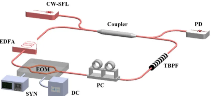
We consider the fiber loop depicted in Fig. 1. It contains an electro-optic amplitude modulator (EOM) that induces a dual-sideband frequency shift per round-trip fm, and an erbium-doped
fiber amplifier (EDFA) providing gain that partially compensates for the loop losses and enhances the number of relevant round-trips inside the loop, as in AOFS-based loops. Besides, an optical filter permits to limit the output bandwidth and efficiently reduces parasitic loop oscillations, while a polarization controller also stabilizes the loop operation. The round-trip time is τ = nL/c, where n is the group index of the loop fiber. This leads to a fundamental loop frequency fc = 1/τ. A 2 × 2 optical coupler enables to seed the loop and to
extract a fraction of the circulating laser power. The EOM is driven by a radiofrequency synthesizer (SYN) and a bias voltage (DC). We assume that the loop is below the laser threshold, i.e., the gain does not compensate for the losses. The setup is similar to the one of Refs [11–13] but the frequency-shift is provided by a common EOM instead of an AOFS.
Fig. 1. Sketch of the dual side-band FS loop. CW-SFL: continuous-wave single-frequency laser; PD: photodiode; TBPF: tunable bandpass filter; PC: polarization controller; EOM: Mach-Zehnder intensity modulator driven at frequency fm (SYN) and bias voltage Vb (DC); EDFA: erbium-doped Optical Fiber Amplifier.
2.2. Model
In order to predict the output waveform, we derive a time-delayed interference model. Given the transmission matrix of the coupler [tij] and Ein the input electric field of the coupler, the
output field Eout can be written as follows:
1 11 12 1 2 21 22 2 . out in out in E t t E E t t E = (1)
In the case of a lossless coupler, the tij verify the condition t11t22 – t12t21 = 1 [19]. At round-trip
p, the real transfer function of the EOM can be modeled as Υ(p)(t) = sin[Γ + Γ
msin(2πfm(t–
pτ))], where Γm is the modulating depth that depends on the RF power Pdc. Γ is the static
phase retardance of the EOM that can be controlled by the applied bias voltage Vb. If η and G
are the intensity loss of the loop and the intensity gain parameters, respectively, then we write
G
γ = η the overall amplitude transmission. To find out the field circulating inside the loop, we calculate the electric field at output port 2. From Eq. (1), this field writes:
2( ) 21 1 22 2,
out in in
E t =t E +t E (2)
from which one gets:
(1) 2( ) 21 1( ) 22 2( ) ( ).
out in out
E t =t E t +t γE t− ϒτ t (3)
This formulation can be expanded using
(2) 2( ) 21 1( ) 22 2( 2 ) ( ).
out in out
E t− =τ t E t− +τ t γE t− τ ϒ t (4)
Inserting Eq. (4) into the right-hand side of Eq. (3), the equation can be expanded to N round-trips in the loop:
( ) 2 21 1 21 22 1 1 1 ( ) ( ) ( ) ( ). p N p p l out in in p l E t t E t t t γ t E t pτ = = = +
∏
ϒ − (5)The experimentally accessible and useful signal is at the output port 1. If the input field at port 1 is a single-frequency continuous-wave with power Pin, then
1 ( ) 1 11 21 12 22 1 1 ( ) N p p p l ( ) , out in in p l E t t P t t t −γ t P = = = +
∏
ϒ (6)from which the power Pout(t) can be derived:
2 1 ( ) 11 21 12 22 1 1 ( ) ( ) . p N p p l out in p l P t t t t t −γ t P = = = +
∏
ϒ (7)In the following, we use Eq. (7) to calculate the output waveform. Note that contrary to the theoretical model developed for AOFS loops [11,12], here no simple analytical formula can be deduced. However, under the integer Talbot conditions fm = nfc, where n is an integer, we
find sin[2πfm(t–pτ)] = sin(2πfmt). Then, in the limit N→ +∞, the sum of the geometric series
in Eq. (7) can be simplified, leading to
2 21 12 11 22 sin ( ) ( ) , 1 sin ( ) out in t t t P t t P t t γ θ γ θ = + − (8)
where we introduced θ(t) = Γ + Γmsin(2πfmt). Since t22γsinθ(t) < 1 (assuming t22 real positive),
obviously sinθ(t)/(1–t22γsinθ(t)) will be a sharp function peaked at θ(t) = π/2. As in the
AOFS-based loops, pulses are found when the Talbot condition is met, i.e., when the modulation frequency is an integer number of times the loop frequency (or, equivalently, when the loop length is an integer number of times the beat length). It is interesting to note that Eq. (8) is independent of n, which means that the pulse shape is expected to be the same whatever the modulation frequency, and that the pulses will become shorter as frequency increases. According to Eq. (8), the important point, specific to our amplitude modulation case, is that two temporally separated solutions satisfy Eq. (8) in one period 1/fm. Indeed, we may predict
that the response of the amplitude-modulated loop in the time domain delivers a periodic series of pulse doublets. The delay Δt between the two pulses in one period 1/fm is found to be
1 1 2 / 2 1 sin . 2 m m t f π π − − Γ Δ = − Γ (9)
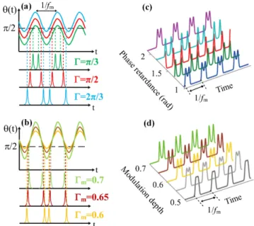
This shows that Γ and Γm will have a strong influence on the delay. Sketches of the output
time responses with different Γ and Γm are depicted in Figs. 2(a)-2(b). For example if Γ = π/2
then Δt = 1/(2fm), leading to a pulse repetition rate equal to twice the modulation frequency
(red curve in Fig. 2(a)).
Fig. 2. Sketches of output signal vs time, with (a) different Γ and (b) different Γm. Simulation
output power with (c) Γ = π/3 (blue), 5π/12 (green), π/2 (red), 7π/12 (light blue), and 2π/3 (purple), and (d) Γm = 0.5 (black), 0.55 (grey), 0.6 (yellow), 0.65 (brown), and 0.7 (green).
To further illustrate the influence of Γ and Γm on the double-pulse operation, we perform
simulations based on Eq. (7) with N = 30 round-trips. Figure 2(c) depicts the simulation results, with Γm = 0.7 and γ = 0.9 for example, showing that the delay between the two pulses
increases with Γ. Then the influence of Γm on the double-pulse is also simulated and depicted
in Fig. 2(d) when Γ = 2π/3. With the increase of Γm, the delay gradually approaches one half
period. Note that Γm also has an influence on the pulse width. Indeed, lower values of Γm will
directly reduce the width of the optical-carried RF comb in the optical frequency domain, hence leading to pulse widening. These predictions are tested experimentally in the following.
3. Pulse doublets experiments
3.1 Experimental parameters
We experimentally investigate the time response of the dual side-band frequency-shifting loop as depicted in Fig. 1. Experiments are performed with a continuous-wave tunable single-frequency semiconductor laser, which delivers 0.5 mW in the C band, with a linewidth of about Δν = 100 kHz. In order to avoid parasitic oscillations when the EDFA gain is raised, we use a 40 GHz-bandwidth (0.3 nm) optical filter inside the loop. Here, at variance with the FS loop of Refs [10–12] where the wavelength of the seed laser is at one edge of the optical filter (single-sideband frequency comb), we set the wavelength of our laser at the center of the optical filter around 1552 nm (dual-sideband frequency comb). From the measured values of the four intensity transmission coefficients, |tij|2 the coupling matrix is set to
0.44 0.65 0.43 0.67 ij i t i =
. The loop fundamental frequency is measured to be fc = 6.737 MHz,
corresponding to a loop delay time τ = 0.148 µs and an optical length of 44.53 m. Note that the coherence length Lc = c/Δν (c is the velocity of light in the medium) of the seed laser
corresponds to more than 60 round-trips, exceeding the N = 30 round-trips used in the simulation. The polarization controller (PC) is utilized to stabilize the polarization state of the laser signal to make the modulation depth higher and waveform more stable. In order to minimize the output pulse width (or maximize the optical bandwidth), the polarization state of the laser and the pump current of the EDFA are adjusted jointly. The detection setup consists in a 40 GHz-bandwidth photodiode and a high-resolution optical spectrum analyzer. The signal in time domain is monitored with an 11 GHz-bandwidth and 40 Gs/s sampling-rate oscilloscope.
Finally, the EOM is a 10 GHz-bandwidth Mach-Zehnder modulator with a half-wave voltage of 4 V. The FS loop output characteristics depend on RF frequency fm, RF power Pdc,
and bias voltage Vb.
3.2. Dual-pulse regime
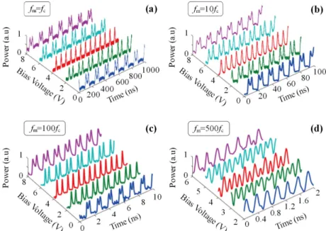
In agreement with the theoretical results obtained with fm = nfc, we find that the time response
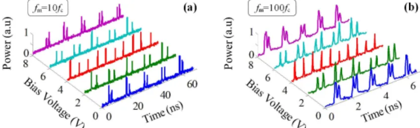
of the dual side-band FS loop is a periodic train of the pulse doublets with a temporal period equal to the inverse of the RF frequency applied to the EOM, as shown in Fig. 3. Figures 3(a)-3(d) report the experimental results when n = 1 (fm = 6.737 MHz), 10 (67.37 MHz), 100
(673.7 MHz), and 500 (3.369 GHz), respectively. The delay is also shown to be continuously adjustable from Δt = 0 to Δt = 1/(2fm) by changing the bias voltage Vb, hence the static
retardance of the EOM, in agreement with Eq. (9). Different traces are selected and depicted in Fig. 3. By comparing Figs. 3(a)-3(c), a striking observation here is that the pulse pattern remains the same, regardless of the value of n over three orders of magnitude, in agreement with the model. Of course the repetition rate scales as n, but it appears that the pulse duration
τp scales as 1/ n, leading to a constant duty cycle τpfm. This is because the harmonics content
does not depend on the modulation frequency. Indeed, when Vb and Pdc are kept constant,
from n = 1 to n = 100 the pulse width decreases from 13 ns down to 130 ps (see Figs. 3(a)-3(c)), yielding a constant τpfm = 0.087. At higher values of n the measurement of the pulse
width is limited by the 28 ps-rise time of the detection (see Fig. 3(d) when fm = 3.369 GHz).
We measure the optical output spectrum by using a 0.06 pm-resolution OSA. As expected, the output optical spectrum contains a dual side-band RF comb, with the seed wavelength at the center and fm-harmonics on both sides. In our experimental conditions, we could generate
a few dozen harmonics. For example, when fm is 673.7 MHz, the total width of the
optical-carried RF comb is 39 × fm = 26.3 GHz, as shown in Fig. 4 (a). Raising the gain to higher
values leads to parasitic oscillations. When fm = 3.369 GHz, Fig. 4(b) shows a 40.4 GHz-wide
but by the optical filter edges. Moreover, we could observe that changes in the bias voltage influences the harmonics intensities. Namely, at Vb = 4 V when the repetition rate is doubled,
odd harmonics are lower than even harmonics. Precisely measuring the short picosecond pulse width (e.g. with an autocorrelator) would permit further analysis of the spectral-temporal relationship.
Fig. 3. Experimental pulse doublet regime when fm = nfc: influence of the modulation frequency fm and the bias voltage Vb. Pdc = 25 dBm; (a) n = 1; (b) n = 10; (c) n = 100; (d) n =
500. In (a)-(b)-(c), Vb = 0 V (blue lines), 2 V (green lines), 4 V (red lines), 6 V (light blue lines), 8 V (purple lines). In (d), Vb = 2 V (blue line), 3 V (green line), 4 V (red line), 5 V (light blue line), 6 V (purple line). Pulse FWHM τp measured when Vb = 4 V: (a) τp = 13 ns, (b) 1.3 ns, (c) 130 ps, (d) 80 ps (detection limit).
Fig. 4. Optical spectrum of the dual side-band FS loop. (a) fm = 673.7 MHz, the two arrows
show the ± 19th harmonics. The total comb width is 39 × f
m = 26.3 GHz. (b). fm = 3.369 GHz
and the two arrows show the –5th to + 6th harmonics. The total comb width is 12 × f m = 40.4
GHz.
The RF power applied to the EOM is another important factor influencing the double-pulse properties. We first keep fm = fc = 6.737 MHz and Vb = 2 V; Figs. 5(a)-5(c) show that by
decreasing Pdc, which corresponds to decreasing the modulation depth Γm, we find that (i) the
pulse width significantly increases and (ii) the delay decreases. The first feature (i) comes from spectral narrowing due to reduction in the harmonics amplitudes, leading to pulse widening. The second feature (ii) can be understood from the sketch of Fig. 2(b) and Eq. (9): the delay depends on Γm, except for the particular point Γ = π/2 where Δt = 1/(2fm) whatever
show an increase in the pulse width while the delay remains constant, in agreement with Eq. (9).
Fig. 5. Influence of RF power on the pulse train. (a),(d) Pdc = 25 dBm; (b),(e) 23 dBm and (c),
(f) 21 dBm. Upper row (blue curves): Vb = 2 V; lower row (red curves): Vb = 4 V. 3.3. Rectangle and triangle waveform generation
Following the preceding conclusions, we find a simple means to generate a rectangle waveform with an adjustable duty cycle. By precisely adjusting Vb and Pdc to make the
falling-edge of the first pulse coincides with the rising-edge of the second, we can obtain a rectangle waveform with different duty cycles. As a typical example, we set fm = 1.0039 GHz
(149fc), and adjust Vb (resp. Γ) and Pdc (resp. Γm) in the experiments (resp. in the simulation).
Figure 6 reports the rectangle waveforms. The FS loop with Pdc = 21 dBm generates a
double-pulse pattern with τp ~300 ps. We first choose the bias to Vb = 1.5 V in order to transform the
double-pulse into a rectangle waveform with a duty cycle of 1:3 (see Fig. 6(a)). When Vb
increases to 2.6 V and Pdc decreases to 20 dBm simultaneously, we obtain the rectangle
waveform with a duty cycle of 1:2, i.e. a square wave, as shown in Fig. 6(b). As a last example, Fig. 6(c) shows a rectangle waveform with a duty cycle of 2:3 in the case of Vb =
3.3 V and Pdc = 19 dBm. Corresponding simulations are depicted in Figs. 6(d)-6(f) showing a
good agreement with the experimental results.
Fig. 6. Rectangle waveform generation; influence of the bias voltage and the RF power on the duty cycle. (a)-(c): Experiment results with (a) Vb = 1.5 V, Pdc = 21 dBm; (b) Vb = 2.6 V, Pdc =
20 dBm and (c) Vb = 3.3 V, Pdc = 19 dBm. (d)-(f): Simulation results with (d) Γ = 1 rad, Γm = 0.6; (e) Γ = 1.2 rad, Γm = 0.5 and (f) Γ = 1.4 rad, Γm = 0.3.
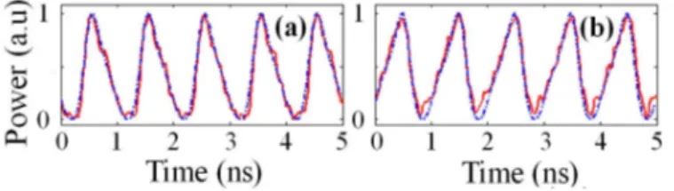
Fig. 7. Saw-tooth waveforms with (a) fm = 1.0028 GHz, (b) fm = 0.99835 GHz. (red line:
The waveform generation is not limited to the rectangle case. It is well known that AOFS loops output waveform relies on the shifting frequency fm, and RF power, and the loop length.
Here, we find saw-tooth waveforms when we slightly detune the modulation frequency of the EOM off an integer value nfc. For example, we set fm = 1.0028 GHz and 0.99835 GHz,
respectively, and find the triangle waveforms reproduced in Figs. 7(a)-7(b). In the experiment, we keep Vb = 3 V and Pdc = 25 dBm. A good agreement with the experiment is
obtained when Γm = 0.6 and Γ = 1.2 in the simulations (see blue dotted lines in Fig. 7),
confirming the validity of the linear model.
4. Mode-locked pulse doublets generation from the un-seeded loop
For the sake of completeness, we investigate shortly the loop behavior without the seed laser when the gain exceeds the losses, i.e., when the loop is driven above laser threshold. It has long been shown that phase or loss modulation of lasers lead to the mode-locked regime when the modulation frequency is a multiple of the cavity free-spectral range [20,21]. In particular picosecond pulse generation was demonstrated in erbium-doped fiber lasers using phase modulators [22–24]. However, contrary to phase-modulated mode-locked lasers, here it appears that amplitude modulation leads to picosecond pulse doublet operation, a situation that, to the best of our knowledge, has never been reported. The EDFA in our set-up allows us to raise the gain up to the laser threshold. We show at first the experimental results when fm =
fc in Fig. 8 (in this case the fiber loop was slightly reduced, leading to fc = 7.611 MHz).
Obviously, the double-pulse regime still exists in this un-seeded mode-locked operation. Furthermore, it is interesting to note that the delay time is continuously tunable and also obeys Eq. (9), as shown for example in Fig. 8 with two different values of the bias voltage. At variance with the seeded case of Section 3, in which the pulse width is about 13 ns, here the laser pulses can be reduced down to τp = 425 ps (when Vb = 4 V). Also in agreement with the
linear model, the un-seeded FS ring laser generates sub-nanosecond pulses when fm = nfc with
n ≠ 1 (harmonic mode-locking). Figure 9 evidences this double-pulse regime, without seed laser, up to n = 100, where harmonic mode-locked pulses have a 70 ps duration.
Fig. 8. Resonant mode-locked double-pulse operation with fm = 7.611MHz. (a) Vb = 4 V. (b) Vb
= 0 V.
Fig. 9. Harmonic mode-locked double-pulse operation. Experimental laser output when (a) fm
5. Conclusion
To sum up, a FSL containing an amplitude modulator and an amplifier produces pulses in the sub-nanosecond range when seeded by a cw laser, if the loop length is a multiple of the RF modulation wavelength applied to the modulator. This experiment shows an alternative approach to AOFS loops, taking advantage of the inherent bandwidth and tunability of the EOM. We have evidenced analytically and experimentally an original regime of pulse doublets that finds its origin in the transfer function of the EOM. It is found that the delay between the pulses is simply governed by the modulator’s bias. In addition, by properly setting the modulation frequency, adjustable rectangle and saw-tooth waveforms can be obtained. Finally the double-pulse regime survives to above-threshold operation: without the seed, mode-locked picosecond pulse doublets are also generated with an adjustable delay.
Beyond this first demonstration, careful characterization and reduction of jitter issues need further work that is under progress. Designing a loop with all polarization-maintaining fiber components, as well as acoustic and thermal isolation, would improve the stability.
The proof-of-concept demonstrated here could be extended to integrated photonics since optical rings, filters, and EOMs can be integrated on photonic platforms. This EOM-based FS loop could address applications already envisioned with FS loops, like high-repetition rate pulse trains [11], RF waveform generation [13,25] and processing [14], or ranging [18,26,27]. Besides, such a scheme may be considered when designing pump-probe experiments, since the delay can be voltage-controlled without using moving delay lines.
Funding
Chinese Scholarship Council (CSC), Région Bretagne, FEDER (EU), and Rennes Metropole, in the framework of CPER SOPHIE-Photonique.
Acknowledgments
The authors thank H. Guillet de Chatellus for stimulating discussions.
References
1. J. P. Yao, “Microwave photonics,” J. Lightwave Technol. 27(3), 314–335 (2009).
2. J. Capmany and D. Novak, “Microwave photonics combines two worlds,” Nat. Photonics 1(6), 319–330 (2007). 3. J. Capmany, J. Mora, I. Gasulla, J. Sancho, J. Lloret, and S. Sales, “Microwave photonic signal processing,” J.
Lightwave Technol. 31(4), 571–586 (2013). 4. C. H. Lee, Microwave Photonics, 2nd ed. (CRC, 2013).
5. X. S. Yao and L. Maleki, “Optoelectronic oscillator for photonic systems,” IEEE J. Quantum Electron. 32(7), 1141–1149 (1996).
6. J.-W. Shi, C.-B. Huang, and C.-L. Pan, “Millimeter-wave photonic wireless links for very high data rate communication,” NPG Asia Mater. 3(4), 41–48 (2011).
7. H.-P. Chuang and C.-B. Huang, “Generation and delivery of 1-ps optical pulses with ultrahigh repetition-rates over 25-km single mode fiber by a spectral line-by-line pulse shaper,” Opt. Express 18(23), 24003–24011 (2010).
8. J. Wells, “Faster than fiber: the future of multi-Gb/s wireless,” IEEE Microw. Mag. 10(3), 104–112 (2009). 9. F. V. Kowalski, S. J. Shattil, and P. D. Hale, “Optical pulse generation with a frequency shifted feedback laser,”
Appl. Phys. Lett. 53(9), 734–736 (1988).
10. H. Sabert and E. Brinkmeyer, “Pulse generation in fiber lasers with frequency shifted feedback,” J. Lightwave Technol. 12(8), 1360–1368 (1994).
11. H. Guillet de Chatellus, O. Jacquin, O. Hugon, W. Glastre, E. Lacot, and J. Marklof, “Generation of ultrahigh and tunable repetition rates in CW injection-seeded frequency-shifted feedback lasers,” Opt. Express 21(13), 15065–15074 (2013).
12. H. Guillet de Chatellus, E. Lacot, W. Glastre, O. Jacquin, and O. Hugon, “Theory of Talbot lasers,” Phys. Rev. A 88(3), 033828 (2013).
13. A. Kanno, I. Morohashi, T. Kuri, I. Hosako, T. Kawanishi, Y. Yasumura, Y. Yoshida, and K. Kitayama, “16-Gbaud QPSK Radio Transmission using Optical Frequency Comb with Recirculating Frequency Shifter for 300-GHz RoF Signal,” in IEEE International Topical Meeting on Microwave Photonics, 2012, 298–301.
14. F. Tian, X. Zhang, J. Li, and L. Xi, “Generation of 50 stable frequency-locked optical carriers for tb/s multicarrier optical transmission using a recirculating frequency shifter,” J. Lightwave Technol. 29(8), 1085– 1091 (2011).
15. H. Guillet de Chatellus, L. R. Cortés, and J. Azaña, “Optical real-time Fourier transformation with kilohertz resolutions,” Optica 3(1), 1–8 (2016).
16. C. Schnébelin and H. Guillet de Chatellus, “Optical spectral shaping with MHz resolution for arbitrary RF waveform generation,” in Conference on Lasers and Electro-Optics, OSA Technical Digest (online) (Optical Society of America, 2018), paper SM1B.7.
17. L. Wang and S. LaRochelle, “Talbot Laser with Tunable GHz Repetition Rate using an Electro-Optic Frequency Shifter,” in Conference on Lasers and Electro-Optics, OSA Technical Digest (online) (Optical Society of America, 2017), paper JW2A.66.
18. H. Yang, M. Brunel, H. Zhang, M. Vallet, C. Zhao, and S. Yang, “RF up-conversion and waveform generation using a frequency-shifting amplifying fiber loop, application to Doppler velocimetry,” IEEE Photonics J. 9(6), 7106609 (2017).
19. A. Yariv, “Universal relations for coupling of optical power between microresonators and dielectric waveguides,” Electron. Lett. 36(4), 321–322 (2000).
20. J. Hirano and T. Kimura, “Multiple mode-locking of lasers,” IEEE J. Quantum Electron. 5(5), 219–225 (1969). 21. A. E. Siegman, Lasers (Mill Valley, 1986).
22. J. D. Kafka, T. Baer, and D. W. Hall, “Mode-locked erbium-doped fiber laser with soliton pulse shaping,” Opt. Lett. 14(22), 1269–1271 (1989).
23. A. Takada and H. Miyazawa, “30 GHz picosecond pulse generation from actively mode-locked erbium-doped fibre laser,” Electron. Lett. 26(3), 216–217 (1990).
24. D. D. Hudson, K. W. Holman, R. J. Jones, S. T. Cundiff, J. Ye, and D. J. Jones, “Mode-locked fiber laser frequency-controlled with an intracavity electro-optic modulator,” Opt. Lett. 30(21), 2948–2950 (2005). 25. H. Guillet de Chatellus, L. Romero Cortés, C. Schnébelin, M. Burla, and J. Azaña, “Reconfigurable photonic
generation of broadband chirped waveforms using a single CW laser and low-frequency electronics,” Nat. Commun. 9(1), 2438 (2018).
26. H. Zhang, M. Brunel, M. Romanelli, and M. Vallet, “Green pulsed lidar-radar emitter based on a multipass frequency-shifting external cavity,” Appl. Opt. 55(10), 2467–2473 (2016).
27. J. Clement, C. Schnébelin, H. G. de Chatellus, and C. R. Fernández-Pousa, “Laser ranging using coherent pulse compression with frequency shifting loops,” Opt. Express 27(9), 12000–12010 (2019).