HAL Id: hal-01052819
https://hal.archives-ouvertes.fr/hal-01052819
Submitted on 13 Feb 2015
HAL is a multi-disciplinary open access
archive for the deposit and dissemination of
sci-entific research documents, whether they are
pub-lished or not. The documents may come from
teaching and research institutions in France or
abroad, or from public or private research centers.
L’archive ouverte pluridisciplinaire HAL, est
destinée au dépôt et à la diffusion de documents
scientifiques de niveau recherche, publiés ou non,
émanant des établissements d’enseignement et de
recherche français ou étrangers, des laboratoires
publics ou privés.
Long coherence times for Rydberg qubits on a
superconducting atom chip
C. Hermann-Avigliano, R. Celistrino Teixeira, T. L. Nguyen, T.
Cantat-Moltrecht, Gilles Nogues, I. Dotsenko, S. Gleyzes, J. M. Raimond, S.
Haroche, M. Brune
To cite this version:
C. Hermann-Avigliano, R. Celistrino Teixeira, T. L. Nguyen, T. Cantat-Moltrecht, Gilles Nogues, et
al.. Long coherence times for Rydberg qubits on a superconducting atom chip. Physical Review A,
American Physical Society, 2014, 90 (4), pp.040502. �10.1103/PhysRevA.90.040502�. �hal-01052819�
G. Nogues,2 I. Dotsenko,1 S. Gleyzes,1 J.M. Raimond,1 S. Haroche,1 and M. Brune1
1
Laboratoire Kastler Brossel, ENS, UPMC-Paris 6, CNRS, Coll`ege de France, 11 place Marcelin Berthelot, 75005, Paris, France.
2
Univ. Grenoble Alpes, Inst. NEEL, F-38042 Grenoble, France. (Dated: February 13, 2015)
Superconducting atom chips and Rydberg atoms are promising tools for quantum information processing operations based on the dipole blockade effect. Nevertheless, one has to face the severe problem of stray electric fields in the vicinity of the chip. We demonstrate a simple method cir-cumventing this problem. Microwave spectroscopy reveals extremely long coherence lifetimes (in the millisecond range) for a qubit stored in a Rydberg level superposition close to the chip surface. This is an essential step for the development of quantum simulation with Rydberg atoms and of a hybrid quantum information architecture based on atomic ensembles and superconducting circuits.
PACS numbers: 03.67.-a,32.80.Ee,32.30.-r
Rydberg atoms [1] are the focus of a renewed interest. They are nearly ideal tools for the exploration of funda-mental quantum behaviors [2] or for the implementation of quantum information processing [3] and quantum sim-ulation [4,5].
The dipole-dipole interaction [6] provides a strong long-range coupling between Rydberg atoms. It re-sults in the dipole blockade phenomenon [7], which pre-cludes the excitation of more than one Rydberg atom in a small sample. Preparation of samples with a pre-cisely determined Rydberg atom number [8, 9] and or-dered structures [10–12] have been proposed and demon-strated. The dipole blockade also leads to efficient quan-tum gates [13, 14] and to optical nonlinearities at the single photon level [15].
The transitions between Rydberg levels are very sensi-tive to millimeter-wave fields, with frequencies compara-ble to those used in circuit quantum electrodynamics [16]. One may envision a hybrid quantum processing archi-tecture, unifying superconducting artificial atoms with an optical field interface based on dipole blockade [17– 19]. This leads us towards the use of cold atom clouds tightly trapped on superconducting atom chips. More-over, superconducting chips offer a very long trap life-time [20, 21], leading to an easy production of Bose-Einstein condensates [22]. Rydberg atoms, which have been trapped in optical lattices [23], can also be trapped on-chip [24].
Rydberg atoms near a chip set a formidable experimen-tal challenge, due to their sensitivity to static stray elec-tric fields (Stark effect) [25,26]. The patch effect due to adsorption of residual gas [27] or of alkali atoms onto the chip [28,29] is particularly harmful. In particular, each cooling and trapping sequence releases a large number of alkali atoms, which stick onto the chip. They create a patch of dipoles, resulting in inhomogeneous electric fields, which destroy atomic coherences and evolve on an hourly basis. This jeopardizes the practical use of alkali
Rydberg atoms on a chip [30–33] unless this problem can be circumvented. The stray field control methods pro-posed so far either do not apply to alkali deposits [27] or require specific conditions, which might not be compati-ble with most experiments [29,34].
We demonstrate in this paper the coherent manipula-tion of Rydberg atoms by microwave spectroscopy near a chip surface. We observe coherence times in the millisec-ond range. We get rid of the stray field problem by simply covering the front surface of the chip with a thin metal-lic Rubidium layer, making further uncontrolled atomic depositions harmless. These results open a promising av-enue for the use of dipole blockade in quantum simulation and hybrid quantum information processing.
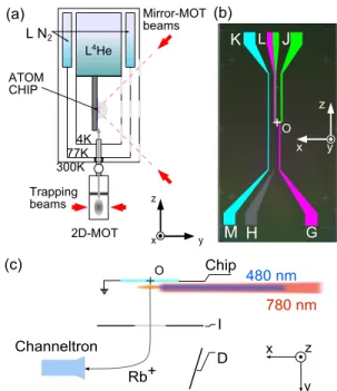
Figure 1(a) presents the experimental system (for de-tails see [22]). The chip is held vertically in a4He-cooled cryostat at 4.2 K. Rubidium-87 atoms are sent upwards towards the chip from a 2D-MOT source (provided by the SYRTE - Syst`eme de R´ef´erence Temps Espace - lab-oratory). They are caught, a few millimeters away from the chip, in a mirror-MOT, whose quadrupolar mag-netic field is provided by centimeter-sized superconduct-ing coils. The mirror-MOT uses two 780 nm laser beams [red arrows on figure1(a)] reflected on the front gold sur-face of the chip and two others, counter-propagating in the x direction (see axis orientations in Fig. 1).
The cold atom cloud is then transferred into an on-chip mirror-MOT. Figure1(b) presents a scheme of the chip. The conducting lines are etched by Reactive Ion Etching out of a 1.7 µm-thick Niobium film deposited on an oxidized silicium substrate. The U -shaped wire (width 300 µm), connecting the J and L pads, used together with a uniform field bias creates the quadrupole field for the on-chip MOT.
The atoms are then cooled down to 12 µK by an optical molasses, and optically pumped in the 5S, F = 2, mF = 2
state. They are transferred into a Ioffe-Pritchard mag-netic trap, whose field is generated by a uniform bias and
2 x z y Chip 480(nm 780(nm I(( D Rb3 Channeltron K L J M H G Pa2 Pc2 Pb2 z y x Mirror-MOT beams ATOM CHIP 2D-MOT Trapping beams 300K77K 4K L4He L(N2 O O
FIG. 1. (color online) . (a) Scheme of the experimental set-up. (b) Scheme of the superconducting atom chip. The letters G to M label the current input pads on the chip. (c) Scheme of the field ionization detection system. The field-ionization electrode is I. The electrode D deflects the ions towards the channeltron counter. Note the axes definition in the three panels. The origin O is taken at the center of the horizontal segment of the Z-wire connecting pads G and L. Note that the axis are shown offset with respect to this origin for clarity.
the Z-shaped wire (width: 70 µm), connecting pads G and L. The high critical current (3.6 A) and the reduced length of the horizontal portion of this Z-wire make it possible to achieve tight trapping. The field in the bot-tom of the trap is aligned along the x quantization axis. An ancillary wire, connecting pads K and M , feeds a radio-frequency field for evaporative cooling, optionally leading to Bose-Einstein condensation [22]. We operate here with moderately cooled thermal clouds to avoid den-sity effects [35]. The Bxmagnetic field at the bottom of
the trap is measured directly by RF spectroscopy. The position of the atomic cloud in the z and y di-rection can be changed by adjusting the bias field. The cloud-to-chip distance, y, can be varied from 80 µm to 700 µm. The evaporation is performed at y =80 µm and the cloud is then adiabatically moved and expanded towards its final position.
We then excite the two-photon 5S → 60S transition with a 780 nm beam and a frequency-doubled diode (Top-tica TA-SHG-110) at 480 nm. The detuning with respect to the intermediate 5P3/2 level is 540 MHz. The ‘red’
and ‘blue’ lasers, with waists of 150 and 22 µm respec-tively, propagate along the x axis [Fig. 1(c)], with σ+
and σ− polarizations. They excite the 60S1/2, mj = 1/2
sublevel. Both lasers are frequency-locked to a transfer
- 1 6 0 - 1 4 0 - 1 2 0 - 1 0 0 - 8 0 - 6 0 - 4 0 - 2 0 0 0 2 4 6 8 1 0 1 2 1 4 Io n s ig n a l (a .u .) L a s e r d e t u n i n g ( M H z )
FIG. 2. (color online). Laser spectroscopy of the 5S − 60S two-photon transition. The ion signal (arbitrary units) is shown as a function of the blue laser detuning w.r.t. the expected line position in zero field (dashed vertical line). The black and red/gray points are taken at a 40 minutes time in-terval in a MOT at y =550 µm from the chip with a gold front mirror. The respective line widths are 30 and 40 MHz. The asymmetric Lorentzian line shapes are guides to the eye. The blue triangles show the laser line after the Rubidium metallic layer deposit, in a magnetic trap at y = 670 µm, z = 0. The solid line is a Gaussian fit, with a 1.7 MHz FWHM.
Fabry Perot cavity, whose length is stabilized to a Ru-bidium saturated absorption line.
The laser excitation is pulsed. The blue laser power is 8 mW. The red intensity is adjusted between 100 nW and 2 µW, so that ' 0.3 Rydberg atom is produced by each pulse. We thus avoid dipole-dipole effects, which are not the focus of this study. The largest two-photon Rabi frequency is 27 kHz. Up to 300 excitation pulses, at a 3 ms time interval, are sent on the same atomic cloud without notable degradation of the trap. The atomic cloud is renewed every 8 seconds.
The Rydberg atoms are detected by field-ionization [Fig. 1(c)]. A voltage ramp Vi is applied on the
elec-trode I facing the chip (kept at the ground voltage). The resulting field reaches at different times the ioniza-tion thresholds of the Rydberg levels (37 V/cm for 60S). The ions are accelerated and deflected (electrode D) to-wards a channeltron counter (Sjuts Optotechnik KBL 10 RSEDR). The detection efficiency is 90±10%. It is cal-ibrated by comparing the number of detected Rydberg atoms to the corresponding decrease in the number of trapped atoms. Before the ionization ramp, we minimize the Ey field component by a applying a compensation
voltage Vc on the ionization electrode I.
The first laser spectroscopy with the chip’s gold front mirror confirmed the stray field problem [29,33]. Figure 2present a laser spectrum in a MOT at y =550 µm (black points). The linewidth is 30 MHz in spite of the Ey
mini-mization (application of a 3.7 V/cm compensation field). It increases up to 40 MHz in a 40 minutes time interval, while the line center drifts by 12 MHz (red/gray points). Note that the Zeeman effect due to the MOT quadrupolar field is much smaller than the observed linewidth. These
a Rb deposit onto the gold mirror. Using the cloud size (≈ 200 µm) and the -90 MHz/(V/cm)2 quadratic Stark shift of the 60S level, we estimate the field gradient to be ≈12 V/cm2. This value is incompatible with the use
of atom chips for the dipole blockade, not to mention quantum information manipulations.
Stray fields may be reduced if the cold Rubidium atoms adsorb onto a Rb metallic mirror, which is an excellent optical reflector at 780 nm [36]. We have installed two Rb dispensers (SAES Getters 5G0125), thermally iso-lated from the chip and aiming directly at its surface (shields protect other parts, including the channeltron and the optical windows). After cooldown at 4.2 K, the dispensers were activated for a few minutes. In spite of their high operating temperature, they did not heat the experiment above 12 K. Rb atoms thus rapidly stick onto the chip surface. Using the dispensers’ capacity and ge-ometrical considerations, we expect that the Rb layer is nearly uniform over the chip, with a ≈90 nm thickness.
The blue triangles in Fig. 2 present an optical excita-tion spectrum recorded after this deposiexcita-tion and the op-timization of Vcin a magnetic trap at y = 670 µm, z = 0.
The width is reduced down to 1.7 MHz, mainly limited by laser linewidth. The center of the line is quite close to the expected position in zero field (dotted vertical line). This result evidences the dramatic improvement provided by the Rb coating on the optical spectrum. The line re-mained stable for months, provided the set-up is always kept at a low temperature, precluding any desorption.
We now use microwave spectroscopy in the smaller and colder magnetic trap to investigate the coherence of Ry-dberg level superpositions. We first estimate the resid-ual electric field by studying the one-photon transitions 60S1/2, mJ = 1/2 → 60P3/2, mJ = 3/2 and mJ = −1/2
at 17.29 GHz. Their degeneracy is lifted by the Bxtrap
magnetic field and they have a high Stark polarizability [about -500 MHz/(V/cm)2]. The microwave pulse is
pro-duced by a frequency-stabilized Anritsu generator and sent on the atoms through an optical access.
We recorded the microwave spectra for y between 150 and 675 µm and z = 0. For each y value, we mini-mize Ey by adjusting Vc to get the highest transition
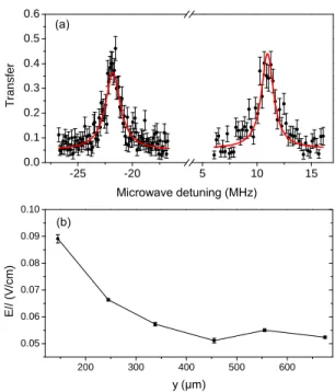
frequency. The resulting compensation field, found to be independent on y, is 0.09 (2) V/cm, nearly two orders of magnitude smaller than that observed before Rubid-ium deposition. Fig. 3(a) presents the spectrum of the two transitions at y = 455 µm. Their common zero field frequency is known within 50 kHz from direct quantum defect measurements [37]. The microwave pulse duration is 20 µs and the FWHM of the resonances ≈1.4 MHz.
From the position of the two lines and the known Zee-man and Stark effects, we deduce the Bx magnetic field
and the uncompensated Ekelectric field component
par-allel to the chip surface. The magnetic field (Bx = 8.71
Gauss for y = 455 µm) agrees within '2% with the
re-- 2 5 - 2 0 5 1 0 1 5 0 . 0 0 . 1 0 . 2 0 . 3 0 . 4 0 . 5 T ra n s fe r Microwave detuning (MHz) (a) 2 0 0 3 0 0 4 0 0 5 0 0 6 0 0 0 . 0 5 0 . 0 6 0 . 0 7 0 . 0 8 0 . 0 9 0 . 1 0 E // ( V /c m ) y (µm) (b)
FIG. 3. (color online) (a) Spectroscopy of the 60S1/2, mJ =
1/2 → 60P3/2, mJ = −1/2 (left) and mJ= 3/2 (right)
transi-tions in the magnetic trap at y = 455 µm from the chip. The transfer probability is shown as a function of the microwave detuning w.r.t the zero field line position. The points are experimental, with statistical standard deviation error bars. The red lines are Lorentzian fits. (b) Parallel electric field modulus, |Ek|, with respect to the atom-chip distance y.
sult of RF spectroscopy. Figure3(b) gives |Ek| versus y. The uncompensated field component is largest close to the chip, and always below 0.1 V/cm.
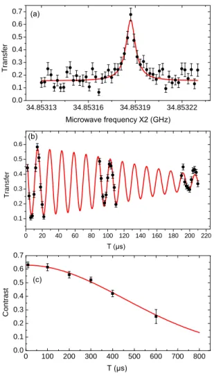
We investigate the coherence time for a Rydberg atom qubit by focusing on the 60S → 61S two-photon tran-sition, at 2 × 17.427 GHz, whose quadratic Stark shift is -10.9 MHz/(V/cm)2. We operate at y = 455 µm and adjust the z position at −350 µm, by minimizing the linewidth. Figure 4(a) presents the line obtained with a 300 µs microwave pulse. The width is 6.6 kHz, corre-sponding to a very encouraging coherence time. However, this line could be broadened by noise on Vc.
Ramsey spectroscopy [38], which is less sensitive to this noise, provide a better estimate of the transverse relaxation time, T2∗. We apply to the atoms two π/2 mi-crowave pulses (duration 0.3 µs) separated by a variable time interval T . Figure4(b) presents the signal as a func-tion of the delay T . The oscillafunc-tion of the Ramsey fringes is at the chosen 70 kHz detuning between atomic tran-sition and microwave. A simple model of field-gradient-induced decoherence leads to a Gaussian envelope for the fringe contrast decay. Using this model as a fitting func-tion [solid line in Fig.4(b)], we get a 1/e relaxation time T2∗ = 163 µs. It would correspond to a field gradient of 0.2 V/cm2 (0.4 V/cm2) in the x (z) direction, estimated
4 0 2 0 4 0 6 0 8 0 1 0 0 1 2 0 1 4 0 1 6 0 1 8 0 2 0 0 2 2 0 0 . 1 0 . 2 0 . 3 0 . 4 0 . 5 0 . 6 T ra n s fe r T (µs) (b) 3 4 . 8 5 3 1 3 3 4 . 8 5 3 1 6 3 4 . 8 5 3 1 9 3 4 . 8 5 3 2 2 0 . 0 0 . 1 0 . 2 0 . 3 0 . 4 0 . 5 0 . 6 0 . 7 T ra n s fe r Microwave frequency X2 (GHz) (a) 0 1 0 0 2 0 0 3 0 0 4 0 0 5 0 0 6 0 0 7 0 0 8 0 0 0 . 0 0 . 1 0 . 2 0 . 3 0 . 4 0 . 5 0 . 6 0 . 7 C o n tr a s t T (µs) (c)
FIG. 4. (color online) (a) Spectroscopy of the 60S → 61S two-photon transition. The transfer probability is shown as a function of twice the applied microwave frequency. The points are experimental with statistical standard deviation error bars. The line is a Lorentzian fit. (b) Ramsey spec-troscopy of the 60S → 61S transition at y = 455 µm and z = −350 µm. The transfer probability is shown as a func-tion of the delay T between the two π/2 pulses. The dots are experimental, the red line is a fit. The error bars are the statistical standard deviation. (c) Contrast of the spin echo experiment as a function of the total duration T of the sequence. The line is a Gaussian fit.
The longer coherence time is comparable to the life-time of the 60S Rydberg level, measured to be 210 µs by monitoring the decay of the ionization signal. This lifetime is only slightly shorter than the theoretical value (240 µs) at zero temperature. It is mainly determined by direct decay to the 5P level by emission of a UV photon and by thermally induced microwave transitions to the closest P Rydberg states. We infer from the measured lifetime an effective microwave temperature of 36 K.
Stray field gradients reduce the Ramsey coherence time. We access the homogeneous transverse relaxation time, T2, trough a spin echo sequence. At time T /2, we
apply a π microwave pulse, resulting in a revival of the
Ramsey signal at time T . Figure4(c) presents the con-trast of this revival as a function of T for y = 455 µm and z = −350 µm, together with a Gaussian fit. The co-herence lifetime (at 1/e contrast) is T2 = 631 µs, nearly
thrice the atomic state lifetime (at y = 150 µm, we still observe T2 = 116 µs). Obviously, we detect, as in the
Ramsey experiment, only those atoms that have survived over T . This explains why the statistical error bars get larger when T increases. This coherence time is nearly two orders of magnitude larger than those observed on previous spectroscopic investigations of the microwave spectra in similar conditions [39]. The coherence is likely to be limited by the residual motion in the field gradi-ents and by the noise on Vc at a frequency of the order
of 1/T . Taking into account the above estimations of the gradients, we infer that the electrical noise dominates.
In conclusion, we have observed near a superconduct-ing atom chip Rydberg levels coherence times exceedsuperconduct-ing their lifetime. The stray electric field gradients due to ad-sorbed Rubidium atoms have been strongly reduced by covering the whole chip with a metallic Rubidium layer. This layer is quite stable in a cryogenic environment.
These results are extremely encouraging for the obser-vation of the dipole blockade in this context. All experi-ments reported here have been performed with a low den-sity of Rydberg atoms. We are now investigating denden-sity effects, which will be reported elsewhere.
This makes us confident that selected Rydberg atom numbers could be produced on-chip, opening the way to interesting quantum simulations of condensed mat-ter problems [4, 5]. On the longer terms, the route to-wards a hybrid quantum information processing architec-ture based on circuit QED and Rydberg atoms remains open [17–19].
This research has been supported by the EU Marie Curie Action CCQED, Project 264666, by the EU ICT Project SIQS Number 600645 and by the DECLIC ERC project.
[1] T. F. Gallagher, Rydberg Atoms (Cambridge University Press, Cambridge, 1994).
[2] S. Haroche and J.-M. Raimond, Exploring the quantum: atoms, cavities and photons (Oxford University Press, 2006).
[3] M. Saffman, T. G. Walker, and K. Mølmer, Rev. Mod. Phys. 82, 2313 (2010).
[4] M. M¨uller, S. Diehl, G. Pupillo, and P. Zoller, in Ad-vances in Atomic, Molecular, and Optical Physics, vol-ume 61, edited by E. A. Paul Berman and C. Lin (Aca-demic Press, 2012), pp. 1 – 80.
[5] H. Weimer, M. Muller, I. Lesanovsky, P. Zoller, and H. P. Buchler, Nat Phys 6, 382 (2010).
[6] R. L¨ow, H. Weimer, J. Nipper, J. B. Balewski, B. Butscher, H. P. B¨achler, and T. Pfau, Journal of Physics B: Atomic, Molecular and Optical Physics 45,
[7] M. D. Lukin, M. Fleischhauer, R. Cˆot´e, L. M. Duan, D. Jacksch, J. I. Cirac, and P. Zoller, Phys. Rev. Lett. 87, 037901 (2001).
[8] Y. O. Dudin and A. Kuzmich, Science 336, 887 (2012). [9] M. Ebert, A. Gill, M. Gibbons, X. Zhang, M. Saffman,
and T. G. Walker, Phys. Rev. Lett. 112, 043602 (2014). [10] T. Pohl, E. Demler, and M. D. Lukin, Phys. Rev. Lett.
104, 043002 (2010).
[11] G. Pupillo, A. Micheli, M. Boninsegni, I. Lesanovsky, and P. Zoller, Phys. Rev. Lett. 104, 223002 (2010).
[12] P. Schausz, M. Cheneau, M. Endres, T. Fukuhara, S. Hild, A. Omran, T. Pohl, C. Gross, S. Kuhr, and I. Bloch, Nature 491, 87 (2012).
[13] T. Wilk, A. Ga¨etan, C. Evellin, J. Wolters, Y. Miroshny-chenko, P. Grangier, and A. Browaeys, Phys. Rev. Lett. 104, 010502 (2010).
[14] L. Isenhower, E. Urban, X. L. Zhang, A. T. Gill, T. Henage, T. A. Johnson, T. G. Walker, and M. Saffman, Phys. Rev. Lett. 104, 010503 (2010). [15] O. Firstenberg, T. Peyronel, Q.-Y. Liang, A. V.
Gor-shkov, M. D. Lukin, and V. Vuletic, Nature 502, 71 (2013).
[16] M. H. Devoret and R. J. Schoelkopf, Science 339, 1169 (2013).
[17] D. Petrosyan, G. Bensky, G. Kurizki, I. Mazets, J. Majer, and J. Schmiedmayer, Phys. Rev. A 79, 040304 (2009). [18] S. D. Hogan, J. A. Agner, F. Merkt, T. Thiele, S. Filipp,
and A. Wallraff, Phys. Rev. Lett. 108, 063004 (2012). [19] J. D. Pritchard, J. A. Isaacs, M. A. Beck, R. McDermott,
and M. Saffman, Phys. Rev. A 89, 010301 (2014). [20] A. Emmert, A. Lupascu, G. Nogues, M. Brune, J.-M.
Raimond, and S. Haroche, Eur. Phys. J. D 51, 173 (2009).
[21] G. Nogues, C. Roux, T. Nirrengarten, A. Lupascu, A. Emmert, M. Brune, J.-M. Raimond, S. Haroche, B. Placais, and J. J. Greffet, EPL 87, 13002 (2009). [22] C. Roux, A. Emmert, A. Lupascu, T. Nirrengarten,
EPL 81, 56004 (2008).
[23] S. E. Anderson, K. C. Younge, and G. Raithel, Phys. Rev. Lett. 107, 263001 (2011).
[24] P. Hyafil, J. Mozley, A. Perrin, J. Tailleur, G. Nogues, M. Brune, J.-M. Raimond, and S. Haroche, Phys. Rev. Lett. 93, 103001 (2004).
[25] C. Fabre, P. Goy, and S. Haroche, J. Phys. B10, L183 (1977).
[26] C. Kocher and C. Taylor, Phys. Lett. A 124, 68 (1987). [27] T. Thiele, S. Filipp, J. A. Agner, H. Schmutz, J. Dei-glmayr, M. Stammeier, P. Allmendinger, F. Merkt, and A. Wallraff, Phys. Rev. A 90, 013414 (2014).
[28] J. M. McGuirk, D. M. Harber, J. M. Obrecht, and E. A. Cornell, Phys. Rev. A 69, 062905 (2004).
[29] K. S. Chan, M. Siercke, C. Hufnagel, and R. Dumke, Phys. Rev. Lett. 112, 026101 (2014).
[30] A. Tauschinsky, R. M. T. Thijssen, S. Whitlock, H. B. van Linden van den Heuvell, and R. J. C. Spreeuw, Phys. Rev. A 81, 063411 (2010).
[31] R. P. Abel, C. Carr, U. Krohn, and C. S. Adams, Phys. Rev. A 84, 023408 (2011).
[32] J. D. Carter and J. D. D. Martin, Phys. Rev. A 83, 032902 (2011).
[33] H. Hattermann, M. Mack, F. Karlewski, F. Jessen, D. Cano, and J. Fort´agh, Phys. Rev. A 86, 022511 (2012). [34] L. A. Jones, J. D. Carter, and J. D. D. Martin, Phys.
Rev. A 87, 023423 (2013).
[35] J. B. Balewski, A. T. Krupp, A. Gaj, D. Peter, H. P. Buchler, R. Low, S. Hofferberth, and T. Pfau, Nature 502, 664 (2013).
[36] N. V. Smith, Phys. Rev. B 2, 2840 (1970).
[37] W. Li, I. Mourachko, M. W. Noel, and T. F. Gallagher, Phys. Rev. A 67, 052502 (2003).
[38] N. F. Ramsey, Molecular Beams, International Series of Monographs on Physics (Oxford University Press, Ox-ford, 1985).
[39] J. D. Carter and J. D. D. Martin, Phys. Rev. A 88, 043429 (2013).