an author's
http://oatao.univ-toulouse.fr/22987
https://doi.org/10.1016/j.compositesa.2018.01.018
Labanieh, Ahmad Rashed and Garnier, Christian and Ouagne, Pierre and Dalverny, Olivier and Soulat, Damien
Intra-ply yarn sliding defect in hemisphere preforming of a woven preform. (2018) Composites Part A: Applied Science
and Manufacturing, 107. 432-446. ISSN 1359835X
Intra-ply yarn sliding defect in hemisphere preforming of a woven preform
Ahmad Rashed Labanieh
a,⁎, Christian Garnier
b, Pierre Ouagne
b, Olivier Dalverny
b,
Damien Soulat
aaUniversity of Lille, GEMTEX, ENSAIT, 2 allée Louise et Victor Champier, 59056 Roubaix, France bLGP, ENIT, 47 avenue d'Azereix, 65016 Tarbes, France
Keywords: A. Fabrics/textiles B. Defects B. Internal friction E. Preforming
A B S T R A C T
Preforming is thefirst step to manufacture a complex composite part via Liquid Composite Moulding processes. The defects that may be encountered during this phase within the preform architecture may decrease the ex-pected mechanical performances of thefinal part. The intra-ply yarn sliding is a defect frequently observed during preforming of a woven preform but its mechanism is far from being fully understood. The aim of this study is to analyse the mechanism of this defect arising when preforming of a carbon woven fabric into hemi-spheric shape. An experimental study followed by analytical analysis was performed to evaluate the effect of the process parameters, material properties and ply configuration conditions on the yarn tension and contact stresses. A significant effect of the yarn tension and the contact shear stresses on the defect occurrence was demonstrated. Based on this analysis, solutions were tested with success to prevent this defect.
1. Introduction
To manufacture complex composite parts, Liquid Composite Moulding (LCM) processes [1] offer a good compromise in terms of
repeatability, production rates, low-energy consumption and lowfinal cost [2]. The first step of these processes consists in draping a dry preform before the liquid resin is injected. Preforming is a difficult phase, and the physical mechanisms are complex because they depend on many parameters (shape of tools, characteristics of the preform, number and orientation of plies, loads applied, etc.). If the mechanical loadings (tension, shear, compression, bending, friction, etc.) to which the reinforcements are subjected during the preforming step have been well described in the literature[3–6], the generation and the control of defects are far from being entirely understood. At the macroscopic scale (preform scale) wrinkling is one of the defects that occurs most often. Boisse et al.[7]recently explained that the frequency of occurrence of the wrinkling defect was related to the weak textile bending stiffness due to possible slippage betweenfibres. Several numerical[8–10]and experimental[11–13]studies focused on the influence of blank holders or other systems to prevent wrinkles. These tools confer global tensile deformations at their vicinity and it was demonstrated that induced tensile forces in thefibre direction prevent wrinkling[14]. In the case of preforming tests on complex shapes of multilayer, which are the subjects of recent papers[2,14–16], Nezami et al.[17]underlined that, friction-based blank holders or other systems may reduce wrinkling, but
induce other defects in the fabric, such as parallel fibre distortions without gaps,fibre distortions with small/large gaps, filament damage, broken or pulled out roving. Except forfilament damage, these defects occur at the mesoscopic scale (tows, yarn). This is also the case of tow buckles. This defect is described in[17–20]. It can be reduced by the control of tensile deformation as shown in[21]. Another type of de-fects, less studied in the literature, can be defined as intra-ply slippage which occurs between the warp and the weft yarns of a woven re-inforcement. In this case, the tow or yarn orientation cannot be con-trolled during the preforming step and the local pore spaces are thus modified. Large empty spaces can be observed between the yarn. Lo-cally, the density of fibre may be reduced to very low values. As a consequence, the local permeability components for the injection steps
[22],[23]are drastically modified, and one can expect to obtain resin
rich zones within the composite part. This surely means that zones of weakness for the composite part are created. Allaoui et al.[13]have experimentally shown large yarn slippage on the vertical faces of a glass plain weave prismatic preform. Boisse et al.[7]described the numerical complexity to model this loss of cohesion of the woven network[24], and the need to use mesoscopic finite element models to allow the possible slippage between yarns. This slippage mechanism was also described during the bias-extension test [3,25], especially for large shear angles. During this test where the analytical kinematic[26,27]
can predict theoretically the shear angle, the differences observed with measured angles can be explained by this slippage between yarns as the ⁎Corresponding author.
E-mail addresses:[email protected](A.R. Labanieh),[email protected](C. Garnier),[email protected](P. Ouagne),[email protected](O. Dalverny),
[email protected] (D. Soulat).
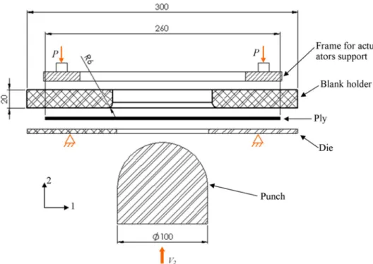
pressures 0.025 and 0.075 MPa that correspond to normal forces by each cylinder equals to 77.9 and 233.7 N respectively, according to the actuator specifications. These operating pressures were chosen after a first preliminary set of test and are related to the appearance of the intra-ply yarn sliding defect. When the minimum operating pressure (0.025 MPa) is applied, no sliding defect occurs. From an applied op-erating pressure of 0.075 MPa this defect takes place. The upper plate is considered as the blank-holder because it is the mobile plate and the normal force (P) is applied on its top surface,Fig. 1. The force (P) is called the holder force all over this paper. The lower plate is considered as the die since it isfixed into position in this machine configuration. For each experiment, the preforming force exerted by the punch is re-corded as a function of the punch displacement. The force measurement is performed by means of a load cell mounted between the punch and the driving actuator. Also, the ply draw-in, border position and yarn arrangement after preforming are captured by a CCD camera. The camera is placed on the top side and its optical axis is aligned with the punch movement path.
2.2. Material properties and ply geometry
The commercial fabric“Hexcel HexForce 48,600 U 1250” was used in this study to perform the experimental work. It is classified as a 2D woven fabric made with a twill 2/2 weaving architecture and con-structed of 3.7 warps/cm and 3.7 wefts/cm with a nominal area density of 600 g/m2 and a nominal thickness of 0.62 mm. The constituent yarns, both warp and weft, are“AS4 C GP 12 K” high strength carbon fibres and they have a linear density of 0.8 g/m. Both yarns are not twisted and not powdered.
The forming tests were conducted using one ply of the woven fabric cut in a square shape with 260 mm side length. The fabric specimens were visually inspected and specifically chosen so that they are free of defect at the beginning of the forming test. The tests were performed using two initial orientations (0° and 45°) of the fabric on the die as presented inFig. 2. The dashed lines sketched on the ply inFig. 2 re-present the warp and weft yarns passing through the punch main axis and aligned with the radius of the hole. These yarns are called radial yarn in the next sections. On the 0° orientation ply, the warp and weft yarns are parallel to the plate side edges, Fig. 2-a. For the 45° or-ientation, the warp and weft yarns are parallel to the plate diagonal and
Fig. 1. Forming machine scheme with characteristic dimensions. All dimensions are in mm.
theoretical kinematic is based on non-slippage mechanisms. This slip-page phenomenon is localised at the intersection of the three zones classically defined in this in-plane shear test. Concerning the in-plane shear behaviour identified by the bias-extension test of an unbalanced woven fabric, Barbagello et al. [28] noted the presence of measurable yarn slippages (up to a maximum that is around 10% of the total length of the yarns). In papers dedicated to the preforming of NCF fabrics
[29–30] intra-ply slippage between fibres has been observed, without
solutions to prevent or reduce this defect qualified as irreversible in
[30]. Except in these studies, few articles of the literature deal with this
type of defect. In this paper, experimental preforming tests were con-ducted on a carbon twill weave fabric. The slippage phenomenon oc-curred in zones with low shear angles, for specific ply orientation. Yarn tensions were analytically computed relatively to tools load to under-stand this slippage defect. The influence of the ply orientation and the ply dimension were experimentally studied to reduce tension in yarns and reduce this slippage. Finally, solutions based on the geometry of tools were proposed to prevent this type of defect.
2. Experimental conditions 2.1. Forming machine
Fig. 1 shows the experimental preforming machine developed at the GEMTEX laboratory [16,31]. The machine is composed of three basic
parts: a punch and two square-shaped plates. In this study, a punch with hemisphere geometry (double curved surface) of a diameter of 100 mm was used. The punch movement is controlled by a pneumatic actuator with a constant mounting speed (45 mm/s).
Both upper and lower plates are a square shaped plate of 300 mm side length. The upper plate is made of Plexiglas and it has a thickness of 20 mm. Both plates have a circular hole in its centre. The hole dia-meter of the upper plate is 110.8 mm and its corner edge is machined from the fabric side. The lower plate is fixed into position whereas the upper one is mobile, parallel to the punch axis. This allows the ar-rangement of the fabric ply between the two plates in the desired or-ientation. The upper plate is subjected to a normal pressure applied by four pneumatic actuators placed on the plate corners. This normal pressure is controlled by the pressure of the compressed air supplied to the actuators. The experiments were conducted with two operating
they create an angle of 45° with plate side edge,Fig. 2-b. The plies with 0° and 45° orientations are denoted across this paper as ply-0 and ply-45 respectively. One can note that the length of the portion of the radial yarns which is in contact with the two upper and lower plates is dif-ferent for both orientations. In ply-0, a half of this length is marked as L0 = 68.6 mm whereas in ply-45 it is marked as L45 = 122.5 mm as illustrated inFig. 2.
3. Definition of the intra-ply yarn sliding defect
Intra-ply yarn sliding occurs relatively frequently when preforming a woven reinforcement. This textile preform is constructed by interla-cing two orthogonal sets of yarn. As a result of this interlacement, an inter-yarn friction force is induced at the over crossing area between the two yarn sets. This force ensures the cohesion of the fabric network and it is responsible of the effort transmission between the yarns. It depends on the fabric architecture, yarn material and structure and yarn tension.
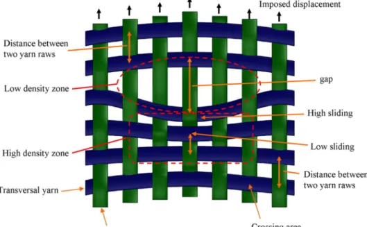
TheFig. 3shows a representative scheme of this defect on a woven preform. When the longitudinal yarns are translated along their main axis (as they are driven by the punch during preforming), they bring the transversal yarns with them by means of the inter-yarn friction force. However, when the applied efforts on a transversal yarn, such as axial tension or tangential friction force on the yarn exposed surface, over-comes the inter-yarn friction force, the transversal yarn is locked into position and the longitudinal yarns slide across it. Thus, a gap occurs between the locked transversal yarns and the last transversal yarn brought with the longitudinal ones. This created defect zone on the preform is characterised onFig. 3as a zone with a low density of the transversal yarns. In the right-below-the-gap zone, the locked yarns accumulate creating a higher density zone. This accumulation of the yarns causes an important increase of the contact pressure and the inter-yarn friction force on the crossing area between the two yarn sets. That enhances the cohesion of the fabric network and stops the yarns slippage. Hence, this defect is a local disarrangement of the transversal
Fig. 2. Dimensions and placement of the plies on the machine under the blank holder plate, ply-0 (a) ply-45 (b). Dashed lines represent the radial warp and weft yarns. All dimensions are in mm.
Fig. 3. Representative scheme for the intra-ply yarn sliding defect on a plain woven ply.
yarn alignment.
Hence, the intra-ply yarn sliding defect could be defined as a loss of cohesion between the two orthogonal yarn sets constructing the woven ply[24]. It occurs in the ply plane (no out-of-plane deformation) and it is characterised by a low density zone (with a gap) followed by a higher density zone,Fig. 3. The amplitude of this defect can be expressed by the gap length and width and number of the involved yarns. It is im-portant to note that the amplitude of the sliding defect may be large and some transversal yarns on the ply borders may get out of the fabric network, as presented in[24].
4. Results
4.1. Preforming force
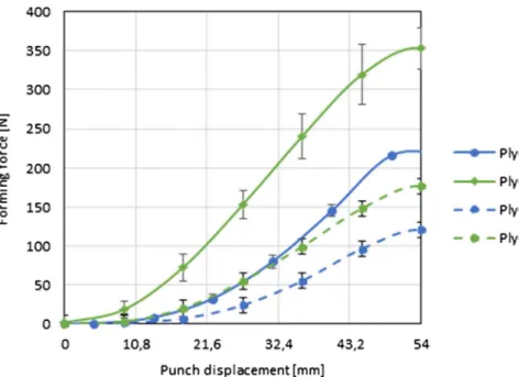
Fig. 4shows the preforming force as a function of the punch dis-placement for both ply-0 and ply-45 when preforming with the two operating pressures for the holder actuators. The experiments were repeated three times at the pressure (0.025 and 0.075 MPa) for both ply orientations. The mean value of the recorded force is presented on the graph with error bars pointing out the standard deviation of the mea-surements. It is clear fromFig. 4that the augmentation of the blank holder force causes the increase of the preforming force for both ply orientations. This is the results of a higher friction force standing against the ply sliding across the die and blank holder surfaces. The preforming of a ply with an initial 45° orientation requires higher effort in comparison to ply-0 in spite of similar blank holder pressure and identical initial ply dimension and shape as shown inFig. 2. The force relative differences are about 56% and 63% for ply-0 at maximum displacement of the punch for the operating pressure of 0.025 MPa and 0.075 MPa respectively.
4.2. Intra-ply yarn sliding defect
Intra-ply yarn sliding defect was observed when preforming ply-45 with 0.075 MPa operating pressure on the three tested samples. However, it was not remarked with lower pressure (0.025 MPa) nor for ply-0 with both applied operating pressures. The intra-ply yarn sliding occurred in the non-sheared zone of the ply on the rounded corner of the upper plate hole,Fig. 5-a.
In order to characterise this defect, the yarns position after pre-forming and the local relative inter-yarn slippage have to be spotted.
However, the carbonfibres are characterised by a light reflecting sur-face. Furthermore, the normal orientation and altitude of the useful part (3D deformed) of the ply surface change during the preforming process. Therefore white dots have been speckled on the apparent yarn surface with an alternative pattern (one with a dot and one with no dot). Namely, for a unit cell of the fabric composed of four warp and four weft yarns, 9 dots are speckled; 4 on corners, 4 on mid-points of side segments and 1 in the centre,Fig. 5-b. The dots have been speckled over a diagonal portion of the ply, as shown inFig. 5-a, where the defect is expected to take place. To distinguish between longitudinal and transversal yarns over this diagonal part, round (red) and cross (blue) marks were superimposed to the white dots on the treated photos.
On the zoomed rectangle zone ABCD defined inFig. 5-a, the yarn slippage defect is expected to take place. The yarns arrangements were observed before and after preforming. Before preforming, that corre-sponds to the initial planar state of the ply (Fig. 5-b), the yarn count per unit length is uniform (same distance between dots). Furthermore, the dots belonging to the transversal yarn are aligned with the corre-sponding longitudinal yarns. The path of the longitudinal yarns was determined by spline connecting the dots. Similarly, the dots belonging to the longitudinal yarns are also aligned with corresponding trans-versal yarns.
After preforming, corresponding to thefinal state of the plyFig. 5-c and d, intra-ply yarn sliding defect occurs on the non-sheared region along the radial yarns on the holder corner when the ply exits from the die-holder zone. Out of the defect region (Fig. 5-d), there is no disar-rangement or misalignment between the two yarn sets. The long-itudinal yarn dots remain aligned with transverse yarn indicating that no yarn sliding takes place. In the defect region, two zones are dis-tinguished: high-density and low-density zone of the transversal yarns. On thefirst one (towards the 3D deformed zone), a gap is created be-tween the last transverse yarn brought by the radial yarn and the next one. About 7 successive transverse yarns along the same radial yarns contribute to this defect and it is expanded across 11 longitudinal yarns. Thefirst transversal yarn from the useful zone side shows the maximum bending. It is therefore associated to a large gap. Below the blank-holder, the transversal yarns accumulate creating a high density zone as schematically represented in Fig. 3. This accumulation of the yarns increases the inter-yarn contact pressure between the two interlaced yarn sets on the crossing areas leading to stop the yarn slippage. Out of the defect region, a moderate misalignment is also observed but with a low amplitude. In the defect zone, no out of plane displacement of yarn
is observed. This is even the case of yarns that bend in the ply plane. In those conditions one may have expected to observe the occurrence of tow buckles[20], but the load of the involved yarns as well as their in-plane bending angle magnitude did not favour the conditions of their occurrence. Otherwise, over the defect zones no transversal disar-rangement of the longitudinal yarn is observed. There is no gap be-tween the longitudinal yarns and the dots placed on the transverse yarns remain aligned along the longitudinal yarns axis.
5. Analysis and discussion
In this section, an analysis of the three main observations revealed over the performed experiments is given. It has for goal to explain why a higher preforming force for ply-45 is required in comparison to ply-0, and also why intra-ply yarn sliding occurs only on ply-45 when higher holder force is applied andfinally why the location of the intra-ply yarn sliding defect takes place on the holder corner edge. Thus in this sec-tion, the effect of the machine configuration, ply geometry and process parameters on the preforming force and the interaction fabric/machine forces that contribute to the appearance of the intra-ply yarn sliding are analysed. Also the location of the defect on the 3D shaped preform is correlated to the fabric/machine interaction stress distribution.
During the preforming process with a hemispheric-shaped punch, the ply behaviour and particularly the deformation are symmetric about two orthogonal planes. The behaviour of the fabric during the preforming process is analysed by observing the behaviour of radial strips of the fabric (relative to the blank holder and die central hole). Two strips may be distinguished on the deformed ply in relation to the dominated deformation mechanisms: tension strip and shear strip. Both strips are illustrated for ply-0 and ply-45 inFig. 6. The tension strip involves one radial yarn, which intersects with the punch translating axis and it is aligned with the hole radius of the blank-holder plate,
Fig. 6-a. The radial yarn on this strip is driven by the punch that pulls it from the die-holder contact zone. During this slid an axial tension on the yarn due to the friction resistance on the contact surfaces (with the other yarns and with the die-holder system) takes place. The shear angle between the radial yarn and the transversal yarns was measured on the planar part of the strip (Fig. 6). The measured angles between the radial and the transverse yarns are globally equal to zero. This in-dicates that no in-plane shear deformation takes place in this zone. Therefore, this strip is mainly submitted to tension deformation. The shear strip is characterised by a trellis of crossing yarns,Fig. 6-c. In order tofit the punch 3D surface shape, the crossing yarns rotate re-lative to each other in the inter-yarn crossing area. The shear angles were measured on the planar part of this strip. The values vary along the strip and a maximum value is observed at the holder corner loca-tion. Therefore, the in-plane shear is considered as the dominating deformation mechanism that takes place in this strip and tension me-chanisms can be neglected. The angle between the two strips is 45° on both ply-0 and ply-45. The ply behaviour between these two strips is seen as an interaction between these two deformation types.
5.1. Analytical analysis of the radial yarn tension on the tension strip The preforming behaviour of the tension strip during the preforming process is analysed separately in order to identify the effect of the material and process parameters on this type of deformation. Therefore, an analytical study of the fabric behaviour during preforming with a simple curved punch surface (hemi-cylindrical) has been conducted,
Fig. 7-a. In this configuration, the fabric strip is arranged in 0° or-ientation relative to the axis-1, as shown inFig. 7-a. The yarns aligned with the axis-1 are called longitudinal yarns. The machine element dimensions and boundary conditions considered previously in the preforming test with double curved surface punch are maintained here.
Fig. 5. intra-ply yarn sliding on ply-45 after preforming with 0.075 MPa operating pressure. Top view (a), zoomed portion (ABCD) before preforming (b), after preforming (c) and zoom on the defect zone after removal of the blank-holder plate (d).
So the die (bottom plate) isfixed into position, the blank holder force is constant during the test and it is aligned with axis-2. The punch is driven from the die toward the blank-holder with the same translation speed. The gravity effect is ignored in this analysis. Furthermore, the machine elements are considered as a rigid body.
Fig. 7-b shows a side view of a half of the preforming machine, as it is symmetric according to plane-1. InFig. 7-b the punch is at its top position. The points a, b, c, d and e are marked inFig. 7-b on the fabric strip in order to describe the different extents of fabric which are in contact with the surfaces of the machine elements. The portion a-b
Fig. 6. Top view of the ply-45 (a) and ply-0 (b) in the deformed state with illustration of the tension and shear strips, representative scheme for the shear strip (c) and tension strip (d).
Fig. 7. Schematic diagrams representing the preforming of a tension strip using a hemicylindrical punch (a), a side view of the machine configuration at the top punch position (b), free body diagram of a portion (a–i) and (i–e) of the strip (c, d respectively).
= −
F P Rdie
2 2 (1)
To assess the internal membrane fabric tension (T) in the long-itudinal yarn direction on the free portion b-c, an imaginary cut is made at a point (i) on this portion,Fig. 7-b. The membrane fabric tension (T) in the longitudinal yarn direction represents the sum of the longitudinal yarn tension forces across the strip width. From the equilibrium equa-tion for the machine parts obtained from the imaginary cut (strip por-tion a-i with punch and strip porpor-tion i-e with dye and blank holder), the relationship between the strip tension (T) and the external forces on the machine elements is expressed in both direction 1 and 2 in Eqs.(2) and (3):
= ′− = − =
F T T R, holder T Rdie;T Tsin β( )
1 1 1 1 1 1 (2)
whereT1andF1is the component in the direction 1 of strip tension (T)
and reaction force (F) on the punch respectively. ′T is the strip tension at point a in the direction 1. This force, ′T, involves the strip tension (T) in the free portion b-d in addition to the friction force induced by the contact between the fabric strip and the punch surface,Fig. 7-c. It could be expressed as ′ =T Teμαwhere the angle (α) represents the total angle of the strip/punch contact area on the outside punch surface. It is equal to the total angle of the strip/holder-corner contact surface (c-d por-tion),Fig. 7-b. μ is the friction coefficient on this contact surface. The two forces ( ′T, F1) are considered for equilibrium condition as the
analysis is performed for a half of the machine for the symmetric condition).
= = − =
T F T, P Rdie;T Tcosβ
2 2 2 2 2 (3)
where (T2) is the component of the strip tension force (T) along the
axis-2 and β is the angle between b–c portion and axis-2. It is the comple-ment of the angle (α). At the beginning of the preforming process where the fabric isflat yet, α is equal to zero. Then it increases gradually as a function of the displacement of the punch. It reaches its maximum value at the punch top position. This maximum value ofα depends on the machine elements geometry. So for this configuration where a constant holder force (P) is applied on the upper plate, theF2,TandR2die
forces can be expressed as a function of the punch displacement (upunch
2 ).
The strip tension (T) is the sum of the axial tension of an individual yarn (ty) over the fabric width. The axial yarn tension (ty) in the pre-forming process results from three deformation mechanisms: the long-itudinal yarn stretching coupled with the transversal yarns tension, the fabric in-plane shear and yarn bending. Thus the fabric tension force can be expressed as:
∑
= + +
T (t t t )
n
stretchingy fabricshearingy bendingy
(4) where n is the number of yarns across the strip width. For the present configuration of the tension strip, the in-plane shear deformation does not take place, Fig. 6. Moreover, the yarn tension generated by the bending deformation can be ignored because of the low carbonfibre bending rigidity. Furthermore, the transversal yarn in the useful zone is not subjected to axial tension.
Two regions are distinguished on the contact surface between the
blank-holder and the fabric strip: the contact surface with the holder flat surface (d-e portion) and the contact surface of the holder rounded corner (c-d portion),Fig. 7-b and d. The total friction force (f1p), aligned with axis-1, on the fabric/flat holder contact surface, which is exactly the same for the fabric/die contact surface, is the integration of the friction shear stress (τp) along the strip contact length (L), which de-creases as a function of the punch displacement, and a given strip width (w).
∫
=
fp Lτ w dxp
1 0 (5)
The friction force (fp
1) is expressed as a function of the global
fabric-machine element friction coefficient (μ) and normal contact force on thisflat area (Np
2).
=
f1p μ N2p (6)
From the equilibrium equation for the die plate, the component of reaction force in direction 2 (Rdie
2 ) is equal to the normal force (N2p) on
the contact surface between the die and the portion d-e of the strip. So from Eqs.(1), (3)the normal contact force (N )p
2 is expressed as:
= = − = −
Np Rdie P F P Tsinα
2 2 2 (7)
Also, the component of the reaction force in direction 1 (Rdie
1 ) is
equal to the total tangential friction force (f1p) on the contact surface between the die and the portion d-e of the strip.
=
fp Rdie
1 1 (8)
The total normal contact force (Nr) and the total tangential friction force ( fr) for the fabric strip on the holder corner are defined as the integration of the normal contact stress (σNr) and the tangential friction shear stress (τr) along the strip curve on the holder corner, having a radius (r) and contact angle (α), and for the given strip width (w).
∫
∫
= =
fr α τ wr dθ Nr , r ασ w r dθ
Nr
0 0 (9)
Regarding the two components of the total normal and tangential contact force (Nrand fr) on both axis 1 and 2,Fig. 7-d, they could be expressed as:
= =
f1r μ N f2r,2r μ N1r (10)
Considering the free body diagram of the blank-holder plate and its equilibrium equations in both 1 and 2 directions, the following equa-tions are obtained based on Eqs.(2, 7, 8):
−2fp+Tcosα+Nr−fr =0,−Tsinα+fr +Nr=0
1 1 1 2 2 (11)
Using Eqs.(1, 7, 10, and 11), the total normal force components (Nr
1
andNr
2) on the holder corner are expressed as a function of the process
parameters and the strip tension (T): =
+ − + = −
N
μ μP T cosα μsinα N Tsinα μN
1
1[2 ( )],
r r r
1 2 2 1
(12) Here, one may notice the coupling between the strip tension and the normal contact force (Nr
2) on the holder corner. As well as, the coupling
between the normal contact force on the fabric/flat holder (Np
2) and the
strip tension is noted in Eq.(7). Otherwise, one may notice that the normal contact force (N2p) is not constant during the process even with a
constant value of P, Eq.(7). It decreases during the preforming process whereas the normal contact force on the fabric/holder corner contact surface (Nr) increases. This analysis for the relationship between the external forces exerted on each machine elements and the normal and tangential friction force on the plate and corner contact surface is ap-plicable for any strip on the fabric during the preforming process.
Here, the tension of a single yarn of a tension strip on a fabric during preforming process is analysed. In general, the fabric is pulled from the die-blank holder zone when the yarn tension overcomes the friction force on the contact die and blank holder surfaces. At this condition, the presents the strip/punch contact surface. The portion b-c presents the
free length of the fabric where the fabric is not in contact with any machine element. At point b and c, the portion of fabric is respectively tangent to both punch and blank holder corner curved surfaces. The portion c-d presents the contact surface of the fabric with the blank-holder rounded corner. Finally, the segment d-e presents the fabric/ flat part of the blank-holder and fabric/ die contact surfaces.
On Fig. 7, the force (F2) is the component of the preforming force
exerted by the punch in axis-2 direction. It is expressed by the other external forces on the machine elements by the holder force (P) and the
component of the reaction force generated on the die (R2die) in the axis-2 direction:
=
ty 2fpy μαe
1 (13)
wherefpy
1 is the force due to the friction shear stress on the contact area
between this sliding yarn and theflat part of the die and blank-holder surface (Ap).fpy
1 is multiplied by 2 as the strip is exposed to two contact
surfaces (die and holder). The area of this surface is equal to =
Ap wyarnL. Where, wyarnis the sliding yarn width and L is the yarn length under the flat die and holder surface (d-e portion). Np
2 is the
normal force on the yarn/die and yarn/holderflat contact surfaces. The tangential friction force on a yarn (fpy
1 ) is expressed as following: = = = = f τ A N σ S f μσ A μN A S , , py t p p n py n p p p 1 2 1 2 (14)
whereτtis the tangential friction shear stress on the fabric/holderflat and fabric/die contact surfaces andσnis the normal contact stress on these two contact surfaces.Sis the area of the total fabric/die contact surface. It is identical to the fabric/flat holder contact area. Both of the sliding yarn area (Ap) and the fabric contact area on the die surface (S) change during the preforming process depending on the punch geo-metry and they can be expressed as a function of the punch displace-ment. Thus, the tension of one yarn (ty) on a tension strip can therefore be expressed as follows based on Eqs.(13) and (14):
= t μN A S e 2 y p p μα 2 (15)
And based on Eq.(7):
= − = − t μ P F A Se μ P T α A S e 2 ( ) 2 ( sin ) y p μα p μα 2 (16)
For this yarn, the evaluation of the components of the normal contact forces (N1ry, N2ry) and tangential contact forces (f1ry, f
ry
2) on the
holder corner surface during preforming can be expressed as a function of the process parameters and punch preforming force (F2) based on the
yarn tension defined in Eq.(15)and the relationship between:
= =
f1ry μ N f2ry,2ry μ N1ry (17)
Based on Eqs.(12, 14, 15)the contact forces on the blank holder corner can be expressed as a function of the process parameters and punch preforming force (F2):
= + − = − Nry 2fpy fry tycos ,α Nry tysinα fry 1 1 1 2 2 (18) = − + + − N μ P F μ e μsinα cosα 2 ( ) 1 [1 ( )] ry A S μα 1 2 2 p (19) For the present tension strip configuration on simple curved punch, the length of all yarn across the strip width is the same thus (Ap) area is identic and the strip contact area on die surface (S) is equal to:
=
S nAp (20)
Where n is the number of the longitudinal yarns across the strip width. Since the dominating deformation on this strip is the tensile deformation and regarding the identic geometry condition for the longitudinal yarns, the strip tension based on Eq.(15)becomes:
=
T t ny (21)
Based on Eqs.(16), (20)the yarn tension (ty) and the strip tension (T) can be expressed as a function only of the controlled process parameters and fabric dimensions as:
= + t μPe n μsinαe 2 (1 2 ) y μα μα (22) = + T μPe μsinαe 2 1 2 μα μα (23)
To summarize the mathematical derivations presented in the pre-vious lines, Eq.(16)indicates the friction force limit to pull one yarn of the tension strip across the contact surfaces with the machine plates (die and blank-holder). This force corresponds to the yarn tension once the strip slippage initiates on these contact surfaces. Thus this Eq.(16)
permits to evaluate the tension of the radial yarns constituting the tension strip on a fabric during preforming process regardless the punch form. Eq.(23)presents the total fabric tension for the simple curved punch with 0° orientation of the fabric once the slippage of the fabric on the machine plates contact surfaces takes place. It is clear in Eqs.(16, 22, 23)that the yarn tension is proportional to the holder force (P). That coincides with the experimental results for hemispheric pre-forming shown inFig. 4. Also the yarn tension depends on the friction coefficient between the tools and the fabric (µ) and the contact angle (α) at the holder corner. Regarding the friction coefficient (µ) the fabric architecture andfibre surface properties has an impact on the produced membrane fabric tension and preforming force. However, the me-chanical properties of the fabric have no impact on these forces once the fabric, driven by the punch, starts sliding on the machine plates. This issue is detailed in the next section. In Eq.(16)the yarn tension depends also on the ratio (A Sp/ ) of the contact area of the sliding yarn on theflat part of the blank-holder (on the die) relative to the area of contact of the whole preform with the die. The yarn tension (ty), the fabric strip tension (T) and the total friction forces (fr and fp) vary
during the preforming process because of the variation of the contact angle as a function of the punch displacement. The evolution of these forces as a function of the punch displacement will be discussed in a later Section as a function of the machine element configuration and will be at the basis of a discussion about the possible occurrence of the yarn slidding defect.
5.2. Machine design: effect on the yarn tension
Two designs are reported in the literature regarding thefixation and mobility of upper and lower plates on the preforming machine. In other words, the direction of the blank holder force relative to the punch translation direction. For thefirst configuration, corresponding to the machine design employed for the analysis and the experiments con-ducted previously in this study, the lower plate isfixed while the upper plate is mobile. The blank holder force is applied on the upper plate so it is in the opposite direction of the punch translation[24,31],Fig. 1. In the second configuration, the upper plate is fixed while lower plate is mobile and the blank holder force is applied on lower plate in the same direction of the punch translation direction. This configuration corre-sponds to the machine design constructed in PRISME and LAMCOS laboratories[19,33]. The aim of this section consists in analysing the effect of these two machine configurations on the evolution of the yarn tension by using Eq.(16). In thefirst configuration, the normal contact force (N2p) is not constant and it is dependent on the punch
displace-ment as shown by Eq.(7). While in the second configuration, the holder
force is applied on the lower plate. In this case, the normal contact force (Np=P
2 ) is constant as a function of the punch displacement. Thus, the
tension of the longitudinal yarn when the fabric sliding across the die and blank holder surface becomes:
= t μPA Se 2 y p μα (24) In the tension strip configuration, the fabric tension and the total normal contact force components on the holder corner once the fabric sliding takes place becomes:
tension of one yarn (t y) at a point i on b-c portion is equal to the friction force limit. To consider the friction on the corner of the blank holder, the friction force may be expressed, according to the Capstan equation
[32] which describes the evolution of the cord axial tension by the friction on a curved surface. For this general case, the evaluation of the tension of a single yarn of the strip is identified at first. One considers here that the yarn displacement is in the direction of the t yforce, as detailed on Fig. 7-c:
=
T 2μPeμα (25)
=
+ − + = −
N
μ μP T cosα μsinα N Tsinα μN
1
1[2 ( )],
r r r
1 2 2 1
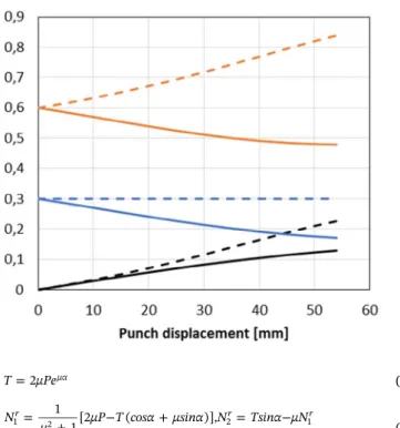
(26) The evolutions of the ratio of the friction limit, corresponding to the fabric tension (T) once the fabric sliding takes place, and the total friction force on the holderflat part and on the holder corner part (fp,
fr) relative to the blank-holder force (P) are plotted inFig. 8for the two machine configurations. Eqs.(10, 12, 22, 25, 26)are used to plot the previously mentioned parameters as a function of the punch displace-ment. Since a dry fabric is used, one considers here only the coulomb friction for the fabric/tool interface with a constant value equal toμ = 0.3, as considered in[24]. This is a general consideration for the fric-tion coefficient and it permits to show the evolution of these forces for identical machine and fabric conditions. The total friction force on the contact surface of the strip/flat-part of the upper plate (f Pp/ ) in the second configuration (dashed blue line inFig. 8) is kept constant during the process as the normal contact force on this surface is constant (N2p=P). In thefirst configuration this force (continuous blue line in
Fig. 8) decreases although the holder force (operation pressure) is maintained constant during the process. The total friction force on the contact surface of the strip/corner-part of the upper plate ( fr/P) in both
configurations (black lines in Fig. 8) increases as a function of the punch displacement as the contact angle (α) increases. However, in the first configuration (blank-holder force applied on the upper plate), the gradient of this increase is less important.
In order to localise the ply regions where a risk of occurrence of the intra-ply yarn sliding defect may take place, the distribution of the tangential shear contact stress have to be assessed. Therefore, the evolution of the friction forces ( fp, fr) should be associated to the evolution of the contact surface areas. That would permit to identify the relationship between the location of the intra-ply yarn slippage defect and the distribution of the contact shear stress.
On the flat part of the upper and lower plates (die and blank-holder), the contact area (Ap) decreases, as the punch goes up, in-dependently of the machine configurations,Fig. 9. In the second ma-chine configuration (the holder force is applied on the lower plate), the friction force ( fp) remains constant (the ratio fp/P plotted in dis-continuous blue line inFig. 8). Consequently the shear contact stress increases as well as the contact area decreases. However, the increase of the tangential shear contact stress is less important in thefirst machine configuration (the holder force is applied on the upper plate) as the friction force ( fp) decreases (the ratio fp/P plotted in blue line in Fig. 8).
On the corner part of the upper plate, the contact area (Ar =Rαw) is
expressed as a function of the corner radius (R), the strip width (w) and the contact angle (α).
The corner radius is a machine geometry parameter. The effect of this parameter is explored in the next section. The contact angle (α) varies from 0°, corresponding to the initial position of the punch, up to a maximum angle corresponding to thefinal position of the punch. Hence, the area Ar increases during the process from zero up to a maximum value at the end of the pre preforming process. The increase of the contact area Aris identical for both machine configurations. In both machine configurations, the total friction force (fr) on the corner part of the contact surface increases, as a function of the punch dis-placement (Fig. 8), leading to an increase of the shear contact stress on this contact region.
However when comparing the two contact areas, Aris much smaller than the Apone resulting in a concentration of the shear contact stress on this contact region. Furthermore, the distribution of the shear stress along this contact surface is not homogeneous. It has a high value at the centre of the contact surface. This concentration of the tangential shear contact stress on the corner part of the upper plate could be correlated to the position of the occurrence of the intra-ply yarn sliding defect on the non-sheared zone of the preform,Fig. 5. When the tangential shear contact stress between the transversal yarns and the corner surface overcomes the inter-yarn friction force, the yarns are stuck on the corner surface while the longitudinal yarns, driven by the punch, slide across the transversal yarns. Therefore, a gap is observed just above the corner surface. The accumulation of the transversal yarns on the corner surface increases the inter-yarns pressure and the inter-yarns friction until it overpasses again the shear contact stress to get out of this zone. The amplitude of the gap (number of transversal yarns stuck on the corner) depends on the value of the tangential shear contact stress and inter-yarns friction contact properties. If one compares the evolution of the friction force between the two machine configurations, a lower tangential shear contact stress takes place on the contact area in the first configuration (holder force applied on the upper plate). This sug-gests that the yarn sliding defect appearance may be delayed or may appear with lower amplitude in that case. Thefirst machine config-uration also leads to a lower membrane tension on the tension strip (Fig. 8) and as a consequence a lower preforming force is expected, Eq.
(2).
5.3. Shear strip
The shear strip consists of a trellis of crossing yarns that shears (relative rotation between the two yarns sets at the crossing area) as a function of the punch displacement tofit the punch surface shape as
Fig. 8. Friction force limit (T P/ ), the friction force on the holder corner ( fr/P) and on the flat part
( fp/P) relative to the holder force as a function of
the punch displacement for two machine config-urations.
shown inFig. 6- c. At the beginning of the process, the crossing yarns shear locally in the free zone. This has for consequence to extend the strip length in this zone and an additional tension in the yarns is gen-erated (denoted fabric shearing force in Eq.(3)). This tension depends on the fabric in-plane shear rigidity. It increases exponentially as a function of the shear angle increase[24]and it gets a high value when the shear angle value approaches to the locking angle. The shear de-formation propogates gradualy into the portion of the strip placed be-tween the two machine plates when the generated shearing effort overcomes the shear contact friction stress imposed on this strip por-tion, Fig. 6-a and b. Therefore the shear angle value is not uniforme along the strip length. It has a high value near the blank hloder corner and much lower values on the strip boarders,Fig. 6-a and b.
5.4. Preforming process with hemispheric-shaped punch
In the frame of the preforming process with a hemispheric-shape punch, the analysis of the evolution of the yarn tension as a function of the punch displacement in the tension strip configuration corresponds to the evolution of the tension of the radial yarns (the yarn that passes at the top of the hemisphere). Moreover, for the other sliding yarns in the useful zone the coupling effect between the longitudinal and the transversal yarn tension as well as the contribution of the fabric in-plane shear deformation will be considered.
5.4.1. Effect of ply orientation
As shown inFig. 4, a change of the ply orientation (0 and ply-45) with the same ply dimensions for the presented machine geometry results in a difference of the recorded preforming forces. The only dif-ference between the two ply orientations is the yarn length over the ply, as mentioned earlier inFig. 2. On the non-sheared zone (involving the radial yarns and neighboring yarns)Figure 6, the radial yarn length in the ply-45 is longer in comparison to the ply-0 (L45 = 121.42 mm and L0 = 68.8 mm). This results in a higher (Ap/S) ratio for the ply-45 and consequently a higher yarn tension and preforming force on the tension strip according to the Eqs.(3) and (16). The tension, the normal contact force and the total tangential friction force for the radial yarn in the two ply orientations, based on the tension strip analysis, are presented in
Table 1. The radial yarn length (L) (as defined inFig. 7) on the die contact surface and the total fabric/die contact surface (S) were mea-sured on the captured photos from the formed plies. The yarn width (particularly important for the calculation of the sliding area) is
considered to be equal to 2.7 mm. It is based on the measured fabric properties (3.6 yarns per cm). The force calculations were determined using the Eqs. (1619) at the initial and final punch positions (u2= 0 mm and u2= 54 mm, respectively), corresponding to a contact
angle for the ply on the corner part of the blank-holder (α = 0° and α = 63.68° respectively). The preforming force (F) is the mean of the recorded values for the conducted tests with an operating pressure of 0.075 MPa corresponding to a blank-holder force (P) of 952 N. One can notice fromTable 1that the yarn length difference induces a higher (Ap /S) ratio for the ply-45 (about 81% larger than for ply 0) at thefinal punch position resulting in a higher yarn tension and higher friction force for the radial yarn (ty, fp, fr) of about 84% at that position for the three parameters. The recorded maximum preforming force on the conducted tests shows a higher value of 63% for the ply-45 in com-parison to ply-0. On the preforming machine used in other research works a disk-shaped plate with a circular hole in its centre is sometimes used instead of the square-shaped plate for the die and blank-holder considered in the present study. With the disk-shaped die, the yarn length on die-holder contact surface is identical and independent of the ply orientation.
5.4.2. Intra-ply yarn sliding defect in hemispheric shaped punch preforming Intra-ply yarn sliding occurs when the friction force between a transversal yarn and the machine tools becomes higher than the inter-yarn friction force at the crossing point. As a consequence, the long-itudinal yarns driven by the punch, such as the radial yarns, cannot bring with them the transversal yarns. Regarding the analytical analysis on the tension strip, the shear friction contact stresses, induced during the preforming process, are also linked to the membrane yarn tension. The yarns tension is not identical over the ply surface. It depends on their orientation relative to the punch and also to their position be-tween the die and the holder plate. The radial yarns are subjected to the highest friction-based tension of the ply as they are the first yarns pulled from the die and holder contact surface. So they are driven by the punch on its longest perimeter. Furthermore, there is no structural in-plane shear on the tension strip that compensates the imposed de-formation,Fig. 6-a and b. Otherwise, based on the analysis performed on the tension strip, the tension of the radial yarns reaches a higher value on the holder corner compared to the tension on theflat holder part. This higher tension is associated to high normal contact forces (Nry) and friction forces ( fry) on the holder corner according to the Eq. (1618). Furthermore, the ply/holder corner contact area (Ar) is small
Fig. 9. Evolution of the contact area (A Ap, r) expressed
in mm2when preforming a tension strip as a function
(Ar < Ap), Fig. 9. That results in a high contact pressure and high
tangential shear contact stress on the holder corner contact surface leading to the occurrence of the intra-ply yarn sliding defect. Regarding the experimental tests result in Section 4.2, the intra-ply yarn sliding defect occurs on the ply-45 in the non-sheared zone along the radial yarns (tension strip) after the blank holder corner where the transversal yarns are stuck on the corner contact surface. This observation coin-cides with the analytical analysis and the assessment of the total friction force on the holder corner ( fry) for the radial yarn given inTable 1. The total friction force at the holder corner reaches a higher value on ply-45 (87% larger than for ply-0).
It was previously indicated in Section 4.2 that the intra-ply yarn sliding defect does not appear on the shear strip. The yarns on this strip respond to imposed preforming displacement by an in-plane shear de-formation tofit the punch form. This deformation is a local structural deformation that does not require the translation of the yarns along its axis. Thus, this deformation mechanism does not favour the mechanism that leads to the yarn sliding defect.
6. Solutions inhibiting the intra-ply yarn sliding defect
The proposed technical solutions in order to inhibit the intra-ply yarn sliding defect occurrence are based on the evaluation of the effect of the ply geometry (radial yarn length) and on the radius (R) of the corner of the blank-holder plate.
6.1. Ply geometry
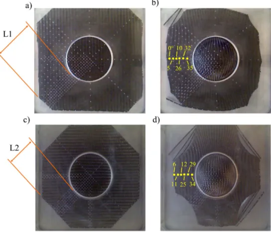
It was noticed in the analysis of the effect of the ply orientation on the preforming behaviour of the ply that the variation of the yarn length on the contact surfaces induces a difference in the yarn tension and preforming force. In order to explore into more depth the effect of the yarn length, two different ply geometries for the ply-45 orientation were considered. The new ply geometries are considered relative to the length of the radial yarn across the machine plates contact surface. The ply corners are cut into two different geometries to obtain two lengths for the radial yarn (L1 and L2) as illustrated inFig. 10. The length L2 is equal to the length of the radial yarn on the contact surface in the ply-0 configuration, (L2=L0=68.6 mm). However, the fabric contact area (S) for ply-45_L2 is smaller than that for ply-0 as shown inTable 1. The
length L1 is defined by the following equation:
= + =
L1 12(L45 L0) 95.5mm.
Preforming tests with a hemispheric shape punch and an operating pressure of 0.075 MPa for the holder actuators were conducted for both ply-45_L1 and ply-45_L2. The deformed plies are shown inFig. 10(b and d). The preforming punch force was recorded in both cases and plot as a function of its displacement (Fig. 11). It clearly appears that a shorter
radial yarn length is associated to a lower preforming force. This ob-servation is completely consistent with Eq.(15)for a tension strip and the results given inTable 1. That reveals the high impact of the yarn tension caused by the friction stress on the contact surfaces (die and blank-holder) on the preforming force. A difference in the preforming force is noted between the ply-0 and ply-45_L2, Fig. 11, even if the radial yarn lengths are identical. This difference may be attributed to a higher fabric contact area (S) for ply-45_L2 resulting in a higher normal contact and friction contact force, Eq.(15),Table 1.
During the experimental tests, the intra-ply yarn sliding defect was only observed on ply-45_L1Fig. 12-a, but with a lower amplitude than the one observed for ply-45 (Fig. 5-d). Only a small gap appears be-tween the transverse yarns on the tension strip in the useful zone. Furthermore, this defect occurs only along the radial yarns near the holder corner, as noticed earlier for ply-45. On the modified ply-45_L2 a slight misalignment can be observed on the non-sheared zone,Fig. 12 -b.
As a conclusion of this section, increasing the length of the radial yarns (or the longitudinal yarn of the non-sheared strip between the contact surfaces with the machine plates) has for consequence to raise the yarn tension resulting in higher preforming force. It also causes the rise of the normal contact force and the frictional force on that radial yarn at the holder corner that enhances the friction force between the transverse yarn and the machine tool at this zone. Consequently, the longitudinal yarns cannot bring the transversal yarns with them and the transversal yarns are locked into position on the holder corner causing the yarns sliding defect. On the contrary, reducing the length of the stretched yarn by cutting the samples corners may be a solution to prevent the occurrence of the yarn sliding defect.
6.2. Blank-holder corner radius
Eq.(16)shows the evolution of the tension of the radial yarn as a function of the angle (α). This angle varies during the preforming process as a function of the punch displacement. However, the angle (α) value at a given punch position also depends on the machine element geometry including the holder corner radius.Fig. 7-b shows the holder corner and the contact angle (α). In this section, the effect of this ma-chine parameter on the preforming force and the intra-ply yarn sliding defect occurrence are investigated. Increasing the corner radius reduces the angle (α) for the presented machine configuration. That leads to a rise of the radial yarn tension, Eq. (15). However, this has also for consequence to reduce the preforming force because of an increase of the value ofcosβ=sinαin the Eq.(2). An increase of the blank-holder corner radius implies an increase of the contact area (Ar =Rαw)
be-tween the ply and the holder corner. That reduces significantly the normal contact stress and tangential friction contact stress on this
Table 1
Radial yarn tension (ty) and frictional contact force on the holder corner (fry) andflat part (fpy) for the ply-45 and ply-0 and both modified plies; ply-45_L1, and ply-45_L2 at both initial
andfinal position of the punch. Angle (α = 0°) at u2_punch = 0 L [mm] Ap[mm2] S [mm2] Ap/S F [N] ty[N] ty/ty_ply-0 fpy[N] fry[N] Ply-45 121.42 655.6 55,017 0.0119 0 6.81 1.82 6,80 0 Ply-45-L1 97.4 525.9 54,168 0.0097 0 5.55 1.48 5,54 0 Ply-45-L2 68.65 370.7 45,892 0.0080 0 4.61 1.23 4,61 0 Ply-0 68.8 371.5 56,676 0.0065 0 3.74 1 3,74 0 Angle (α = 63.68°) at u2_punch = 54 mm L [mm] Ap[mm2] S [mm2] Ap/S F [N] ty[N] ty/ty_ply-0 fpy[N] fry[N] Ply-45 97.8 528.1 44,383 0.0119 353 5.97 1.84 4.27 1.61 Ply-45-L1 71.6 386.6 42356.6 0.0091 324 4.80 1.48 3.43 1.29 Ply-45-L2 43 232.2 32,704 0.0071 248 4.19 1.29 2.99 1.13 Ply-0 42.35 228.7 43,490 0.0052 216 3.24 1 2.32 0.87
contact area (Ar). As a consequence, it reduces the risk of occurrence of the intra-ply yarn sliding defect. Hemispheric preforming tests were conducted again for both ply-0 and ply-45 on the same preforming machine but with another blank holder plates with a corner radius of 6 mm and 12 mm. The operating pressure of the holder actuators was set up to 0.075 MPa for all the conducted experiments.Fig. 13shows the preforming force for the two ply-0 and ply-45 with the two corner radii.
The maximum values of the angle (α) reached at the end of the punch course are about 64° and 59° for the 6 and 12 mm corner radii respectively. The arc length of the ply/holder corner contact surface measures 6.69 mm and 12.4 mm for the corner radii 6 and 12
respectively. That results in an increase of the contact area (Ar) by a 1.85 factor for the corner radius of 12 mm compared to the area for a corner radius of 6 mm.Fig. 13shows the recorded preforming forces for the two ply orientation with the two holder corner radii. Using a higher corner radius leads to a reduction of the preforming force for both ply orientations. However, the radial yarn tension is slightly higher as presented inTable 2for the higher radius. Here, for this new holder plate a higher preforming force is noted in comparison to the previous results shown inFigs. 4 and 11. That is attributed to the difference in the surface properties between the two blank-holder plates. Regarding the intra-ply yarn sliding defect on the zoomed zone illustrated in
Fig. 14, it occurs in the ply-45 with a die radius of 6 mm. A low
Fig. 10. Modified ply-45-L1 and ply-45-L2 in the initial state under blank-holder before preforming (a. c) and after preforming operation (b. d) re-spectively.
Fig. 11. Preforming force of ply-0 and ply-45 with variation of the radial yarn length.
misalignment is also observed in the ply-45 with a die radius of 12 mm. No yarn sliding is observed on the ply-0 with both corner radii. Thus the high increase of the corner contact area for the higher corner radius leads to a significant reduction of the friction shear contact stress pre-venting (reducing) the risk of the occurrence of the intra-ply yarn sliding at the upper plate corner.
7. Conclusions
The behaviour of the “HexForce 48,600 U 1250” carbon woven fabric during the friction-based blank-holders preforming process with a hemispheric-shaped punch was conducted with a particular attention given to the observation of the occurrence of the intra-ply yarn sliding defect. The experiments were performed for two orientations of a mono-ply: ply-0 and ply-45. A higher preforming force is required to form the ply-45. Furthermore, this higher force is associated to the occurrence of the intra-ply yarn sliding defect on the holder corner along the radial yarns in the non-sheared zone.
Fig. 12. Zoomed photo for the ply/holder corner contact zone after preforming operation on ply-45-L1 (a) and ply-45-L2 (b).
Fig. 13. Preforming force of ply-0 and ply-45 with two die corner radiuses 6 and 12 mm.
Table 2
Preforming force (F), radial yarn tension (ty), total friction force and normal contact force
on the radial yarn on the holder corner in addition to the radial yarn/holder corner area (Ar) at thefinal position of the punch with two radius (R) consideration of the holder
corner. R = 6 mm Angle (α = 63.68°) at u2= 54 mm F [N] ty[N] Nry[N] fry[N] Ar[mm2] Ply-45 430 5.20 4.67 1.40 18 Ply-0 279 2.96 2.66 0.80 18 R = 12 mm Angle (α = 59.22°) at u2= 54 mm F [N] ty[N] Nry[N] fry[N] Ar[mm2] Ply-45 321.5 6.14 5.22 1.56 33.48 Ply-0 192 3.27 2.78 0.83 33.48
Two strips from the ply were distinguished relative to the main deformation mechanism: tension strip and shear strip. The yarn tension on the tension strip was analysed analytically and related to the friction on both ply/die and ply/holder contact surfaces. The analytical model shows that the longitudinal yarn tension, once the fabric slippage takes place across the die and the blank holder, depends only on the friction properties of the ply/tool contact surfaces and the applied holder force. This work also showed that the yarn tension is related to its length between the machine plates contact surfaces. The effect of this length was investigated by testing two modified shapes for the ply-45. It was clear that a longer length of the radial yarn on the contact surface in-volves higher tension within the yarns and higher global preforming forces. This higher tension is associated to a higher normal contact and a higher tangential friction contact force on the ply/holder corner contact surface. When the friction between the transversal yarns and the holder corner surface becomes higher than the inter-yarns friction at the yarn crossing area, the radial yarns that are stretched and pulled by the punch cannot bring the transversal yarn with them. That has for consequence to initiate intra-ply yarn sliding that may be considered as a preforming defect as locally, the density of yarn may be severely re-duced and therefore is a zone rich in resin and a potential zone of weakness for the composite part. Consequently, the yarn slippage is associated to the radial yarn tension induced by friction on the machine tool. Thus it is important to localise the zone with the high tangential friction on the ply during preforming and this work proposed it for the studied hemispherical shape.
This work demonstrated also that the yarn tension depends on the angle (α) that is related to the blank-holder corner radius. Two tests for ply-0 and ply-45 were conducted with two radius values (6 and 12 mm). Higher radius leads to increase the yarn tension slightly while the preforming force is reduced. However, as the arc length of the ply/ holder corner contact surface is longer for a larger radius, the tangential friction stress is less important. Consequently, less amplitude for the yarn slippage is observed. The defect is therefore consequently reduced
or even suppressed.
The analytical analysis of the yarn tension for the tension strip permits to investigate the effect of the machine condition relative to the application of the holder force on the upper or lower plate on the predicted preforming force and yarn tension. In the case of applying the force on the upper plate in the opposite direction of the punch move-ment, the yarn tension decreases during the process. When the holder force is applied by the lower plate, the yarn tension increases and it is accompanied by higher normal contact and frictional/contact forces on the holder corner for the radial yarns. Consequently, the risk of oc-currence of the intra-ply yarn sliding defect in this last case is more significant.
The analysis of the evolution of process parameters and the fabric properties (weaving pattern, surface properties of the yarns) should be realised in future works.
References
[1] Boisse P. Advances in composites manufacturing and Process Design. In: Boisse P, editor. Woodhead Publishing Series in Composites Science and Engineering: Number 56; 2015.
[2] Allaoui S, Cellard C, Hivet G. Effect of inter-ply sliding on the quality of multilayer interlock dry fabric preforms. Composites: Part A 2015;68:336–45.
[3] Boisse P, Hamila N, Guzman-Maldonad E, Madeo A, Madeo A, Hivet G, et al. The bias-extension test for the analysis of in-plane shear properties of textile composite reinforcements and prepregs: a review. Int J Mater Form 2016.http://dx.doi.org/ 10.1007/s12289-016-1294-7.
[4] Tephany C, Soulat D, Gillibert J, Ouagne P. Influence of the non-linearity of fabric tensile behavior for preforming modeling of a wovenflax fabric. Text Res J 2016;86(6):604–17.
[5] Harrison P. Modelling the forming mechanics of engineering fabrics using a mu-tually constrained pantographic beam and membrane mesh. Composites: Part A 2016;81:145–57.
[6] Gereke T, Dobrich O, Hubner M, Cherif C. Experimental and computational com-posite textile reinforcement forming: a review. Comcom-posites: Part A 2013;46:1–10. [7] Boisse P, Hamila N, Madeo A. Analysis of defect developments in composite
forming. In: Beaumont PWR, Soutis C, editors. The structural integrity of carbon fiber composites. Springer International Publishing; 2017.
[8] Charmetant A, Orliac JG, Vidal-Sallé E, Boisse P. Hyperelastic model for large
Fig. 14. Zoomed side photo at the holder corner for plies in 0° and 45° orientations with corner radiuses 6 and 12 mm. Misalignment of the white dots illustrates the yarn relative sliding.
deformation analyses of 3D interlock composite preforms. Compos Sci Technol 2012;72(12):1352–60.
[9] Boisse P. Finite element analysis of composite forming. In: Long AC, editor. Composite forming technologies. Cambridge: Woodhead Publishing; 2007. p. 46–79.
[10] Hamila N, Boisse P, Sabourin F, Brunet M. A semi-discrete shellfinite element for textile composite reinforcement forming simulation. Int J Numer Meth Eng 2009;79(12):1443–66.
[11] Sjölander J, Hallander P,Åkermo M. Forming induced wrinkling of composite la-minates: a numerical study on wrinkling mechanisms. Composites: Part A 2016;81:41–51.
[12] Allaoui S, Boisse P, Chatel S, Hamila N, Hivet G, Soulat D, Vidal-Salle. Experimental and numerical analyses of textile reinforcement forming of a tetrahedral shape. Composites: Part A 2011;42(6):612–22.
[13] Allaoui S, Hivet G, Soulat D, Wendling A, Ouagne P, Chatel S. Experimental pforming of highly double curved shapes with a case corner using an interlock re-inforcement. Int J Mater Form 2014;7(2):155–65.
[14] Nezami F Nosrat, Gereke T, Cherif C. Analyses of interaction mechanisms during forming of multilayer carbon woven fabrics for composite applications. Composites: Part A 2016;84:406–16.
[15] Chen S, Endruweit A, Harper LT, Warrior NA. Inter-ply stitching optimisation of highly drapeable multi-ply preforms. Composites: Part A 2015;71:144–56. [16] Wang P, Legrand X, Boisse P, Hamila N, Soulat D. Experimental and numerical
analyses of manufacturing process of a composite square box part: comparison between textile reinforcement forming and surface 3D weaving. Composites Part B 2015;78:26–34.
[17] Nezami F Nosrat, Gereke T, Cherif C. Active forming manipulation of composite reinforcements for the suppression of forming defects. Composites: Part A 2017;99:94–101.
[18] Ouagne P, Soulat D, Hivet G, Allaoui S, Duriatti D. Analysis of defects during the preforming of a wovenflax. Adv Compos Lett 2011;20:105–8.
[19] Ouagne P, Soulat D, Moothoo J, Capelle E, Gueret S. Complex shape forming of a flax woven fabric; analysis of the tow buckling and misalignement defect. Composites: Part A 2013;51:1–10.
[20] Ouagne P, Soulat D, Tephany C, Gillibert J. Measurement of the appearance and growth of tow buckling defect in the frame of complex shape manufacturing process by using fringe projection technique. Strain 2016;52(6):559–69.
[21] Capelle E, Ouagne P, Soulat D, Duriatti D. Complex shape forming offlax woven
fabrics: design of specific blank-holder shapes to prevent defects. Composites: Part B 2014;62:29–36.
[22] Walther J, Simacek P, Advani SG. The effect of fabric and fiber tow shear on dual scaleflow and fiber bundle saturation during liquid molding of textile composites. Int J Mater Form 2012;5:83–97.
[23] Vernet N, Ruiz E, Advani S, et al. Experimental determination of the permeability of engineering textiles: benchmark II. Composites: Part A 2014;61:172–84. [24] Gatouillat S, Bareggi A, Vidal-Sallé E, Boisse P. Meso modelling for composite
preform shaping simulation of the loss of cohesion of the wovenfibre network. Composites: PartA 2013;54:135–44.
[25] Nosrat-Nezami F, Gereke T, Eberdt C, Cherif C. Characterisation of the shear– tension coupling of carbon-fibre fabric under controlled membrane tensions for precise simulative predictions of industrial preforming processes. Composites: Part A 2014;67:131–9.
[26] Cao J, Akkerman R, Boisse P, Chen J, et al. Characterization of mechanical behavior of woven fabrics: experimental methods and benchmark results. Composites: Part A 2008;39:1037–53.
[27] Härtel F, Harrison P. Evaluation of normalisation methods for uniaxial bias-exten-sion tests. Composites: Part A 2014;67:61–9.
[28] Barbagallo G, Madeo A, Giorgio I, Morestin F, Boisse P. Bias extension test on an unbalanced woven composite reinforcement: experiments and modeling via a second-gradient continuum approach. J Compos Mater 2017;51(2):153–70. [29] Margossian A, Bel S, Balvers JM, Leutz D, Freitas R, Hinterhoelzl R. Finite element
forming simulation of locally stitched non-crimp fabrics. Composites: Part A 2014;61:152–62.
[30] Schirmaier F, Weidenmann KA, Kaerger L, Henning F. Characterization of the draping behaviour of sewed unidirectional non-crimp fabrics (UD-NCF). Composites: Part A 2016;80:28–38.
[31] Jacquot PB, Wang P, Soulat D, Legrand X. Analysis of the preforming behaviour of the braided and wovenflax/polyamide fabrics. J Ind Text September
2016;46(3):698–718.
[32] Stephen W. The mechanics of friction in rope rescue. In: International technical rescue symposium (ITRS 99).
[33] Khan MA, Mabrouki T, Vidal-Sallé E, Boisse P. Numerical and experimental ana-lyses of woven composite reinforcement forming using a hypoelastic behaviour. Application to the double dome benchmark. J Mater Proc Technol