OATAO is an open access repository that collects the work of Toulouse
researchers and makes it freely available over the web where possible
Any correspondence concerning this service should be sent
to the repository administrator:
[email protected]
This is an author’s version published in: http://oatao.univ-toulouse.fr/23292
To cite this version:
Gsell, Simon and Bourguet, Rémi
and Braza, Marianna
One- versus
two-degree-of-freedom vortex-induced vibrations of a circular cylinder at Re=3900. (2019) Journal of Fluids
and Structures, 85. 165-180. ISSN 0889-9746
One- versus two-degree-of-freedom vortex-induced
vibrations of a circular cylinder at Re
=
3900
Simon Gsell
a, Rémi Bourguet
b,∗, Marianna Braza
baAix Marseille Université, CNRS, Centrale Marseille, M2P2, Marseille, France
bInstitut de Mécanique des Fluides de Toulouse, CNRS, Université de Toulouse, Toulouse, France
The one- versus two-degree-of-freedom vortex-induced vibrations of a circular cylinder are investigated on the basis of direct numerical simulation results. The Reynolds number, based on the oncoming flow velocity and cylinder diameter, is set to 3900. Three cases are examined: the elastically mounted body is free to oscillate either in the direction aligned with the current (in-line direction; IL case), in the direction normal to the current (cross-flow direction; CF case), or in both directions (IL+CF case). In each case, the behavior of the flow–structure system is studied over a range of values of the reduced velocity (inverse of the oscillator natural frequency). The in-line and cross-flow responses observed in the
IL+CF case substantially differ from their one-degree-of-freedom counterparts, especially
in the intermediate reduced velocity region. In this region, no vibrations develop in the
IL case and in-line oscillations only occur if cross-flow motion is allowed. These in-line
oscillations are accompanied by a major increase of the cross-flow responses, compared to the CF case. The two-degree-of-freedom vibrations are associated with the emergence of large-amplitude higher harmonics in the fluid force spectra. These aspects and more specifically the impact of the existence of a degree-of-freedom and oscillations in a given direction, on the fluid force and structural response in the perpendicular direction, do not seem to be systematically connected to changes in wake topology. Here, they are discussed in light of the orientation and magnitude of the instantaneous flow velocity seen by the moving body.
1. Introduction
Vortex shedding downstream of a bluff body immersed in a cross-flow is accompanied by unsteady fluid forces exerted on the body. If the body is flexible or flexibly mounted, these forces may lead to structural vibrations, called vortex-induced vibrations (VIV). VIV occur when the body oscillation and the unsteady wake synchronize, a mechanism referred to as lock-in. Many natural and industrial systems are subjected to VIV. Their physical analysis and prediction have motivated a number
of research works, as reviewed byBearman(1984),Sarpkaya(2004),Williamson and Govardhan(2004) andPaïdoussis et al.
(2010).
Even though most of real systems subjected to VIV involve slender flexible bodies (e.g. chimneys, marine risers), this phenomenon has been extensively studied through the canonical problem of a rigid circular cylinder mounted on an elastic support allowing oscillations in the cross-flow direction (i.e. perpendicular to the oncoming flow), the direction along
∗
Corresponding author.
E-mail address:[email protected](R. Bourguet). https://doi.org/10.1016/j.jfluidstructs.2019.01.006 0889-9746/
which large oscillation amplitudes are generally expected (e.g.Huera-Huarte and Bearman,2009). Through this simplified
configuration, VIV can be analyzed with a limited number of structural parameters and a single structural mode (e.g.Feng,
1968;Hover et al.,1998;Khalak and Williamson,1999;Govardhan and Williamson,2000;Blackburn et al.,2001;Shiels et al.,2001;Leontini et al.,2006). Significant body oscillations are known to occur over a well-defined range of values of the reduced velocity, defined as the inverse of the oscillator natural frequency non-dimensionalized by the inflow velocity and body diameter. In this range called the lock-in range, the oscillation frequency coincides with wake frequency. The body response amplitude exhibits a bell-shaped evolution as a function of the reduced velocity. Peak amplitudes of the order of
one body diameter can be observed, depending on the structural properties (Khalak and Williamson,1997) and Reynolds
number (Re), based on the oncoming flow velocity and body diameter (Govardhan and Williamson,2000).
The response of an elastically mounted cylinder restricted to move in the in-line direction (i.e. parallel to the oncoming
flow) has also been addressed in prior studies (Aguirre,1977;Naudascher,1987;Okajima et al.,2004;Cagney and Balabani,
2013). In-line oscillations are known to occur over a range of lower reduced velocities, compared to the typical lock-in range
associated with cross-flow VIV. The evolution of the response amplitude as a function of the reduced velocity is characterized by two bell-shaped branches, separated by a region of low-amplitude oscillations. The peak amplitudes are comparable in both branches; they are typically of the order of 0.1 body diameters.
Recently, more attention has been paid to the case where the body is allowed to oscillate in both the in-line and
cross-flow directions.Cagney and Balabani(2014) studied the two-degree-of-freedom VIV of a cylinder in the low reduced velocity
region, where in-line oscillations occur for a single-degree-of-freedom system. No cross-flow oscillations appear in the first branch of in-line oscillations. In the second branch, cross-flow oscillations develop with amplitudes similar to those noted in the in-line direction. In both branches, the in-line response is almost unaltered compared to that observed for a single-degree-of-freedom system. The effect of adding a degree of freedom in the in-line direction on the system behavior for higher
reduced velocities, i.e. where cross-flow oscillations are expected to occur, has been examined byJauvtis and Williamson
(2004). When the structural mass and damping are small, large-amplitude in-line oscillations are superimposed to the
cross-flow responses, and the body typically exhibits figure-eight-shaped trajectories, as also confirmed by several studies (Dahl
et al.,2010;Navrose and Mittal,2013;Gsell et al.,2016). The in-line oscillations are accompanied by an increase of the cross-flow oscillation amplitudes, compared to the one-degree-of-freedom case.
The behaviors of the one- and two-degree-of-freedom systems have been widely studied but most of prior works have considered each system separately. The present study aims at a joint analysis of these system responses, over a range of reduced velocities. Among other aspects, the alteration of the in-line vibrations in the intermediate reduced velocity range, and the evolutions of fluid force statistics and frequency content, when adding/removing a degree of freedom to the system, still need to be investigated. More generally, several connections between the in-line and cross-flow responses remain to be clarified.
In the present work, the behaviors of three distinct systems where the cylinder is free to oscillate either in the in-line direction, in the cross-flow direction, or in both directions, are examined over an interval of reduced velocities encompassing the region of cross-flow VIV. The Reynolds number is set to 3900 as a typical case of the early turbulent regime. The comparison between the structural responses, fluid forces and wake patterns observed for the one- and two-degree-of-freedom systems is based on direct numerical simulation results. Particular attention is paid to the relative impact of the in-line and cross-flow oscillations on fluid forces and simple mechanisms are proposed to shed some light on the responses of the two-degree-of-freedom system.
The paper is organized as follows. The methodology employed in this study is presented in Section2. The behaviors of
the three systems are described Section3. Some elements concerning in-line/cross-flow motion interaction and forcing are
discussed in Section4. The principal findings of this work are summarized in Section5.
2. Method
The physical systems are described in Section2.1. The numerical method and data processing approach are presented in
Section2.2. The tools employed to analyze fluid forces are introduced in Section2.3.
2.1. Physical systems
A sketch of the physical configuration is presented inFig. 1(a). An elastically mounted, rigid circular cylinder of diameter
D and mass per unit length
ρ
cis immersed in a cross-flow. The cylinder axis is parallel to the z axis. The flow, parallel tothe x axis, is characterized by its velocity U, density
ρ
f and dynamic viscosityµ
. The Reynolds number based on U andD, Re
=
ρ
fUD/µ
, is set to 3900. The flow dynamics is governed by the three-dimensional incompressible Navier–Stokes equations. The cylinder is elastically mounted and free to oscillate either in the in-line direction (x axis), in the cross-flowdirection (y axis), or in both directions, as schematized inFig. 1(b); the three distinct cases are referred to as IL, CF and IL+CF,
respectively. The structural stiffness and damping ratio in the i (x or y) direction are designated by kiand
γ
i. All the physicalquantities are made non-dimensional by D, U and
ρ
f. The non-dimensional cylinder displacement, velocity and accelerationFig. 1. Sketch of the physical configuration: (a) general two-degree-of-freedom system, and (b) three cases addressed in this paper, where the cylinder is
allowed to oscillate in the in-line direction (IL), in the cross-flow direction (CF ), or in both directions (IL+CF ).
denotes the span-averaged force in the i direction. The non-dimensional mass is defined as m
=
ρ
c/ρ
fD2; it is set to 2. Thebody dynamics in the i direction is governed by a forced second-order oscillator equation:
¨
ζ
i+
4πγ
i U∗ i˙
ζ
i+
(
2π
U∗ i)
2ζ
i=
Ci 2m.
(1)The reduced velocity in the i direction is defined as Ui∗
=
1/
fnat,i, where fnat,iis the natural frequency in vacuum, fnat,i=
D
/
2π
U√
ki/ρ
c. In the one-degree-of-freedom cases (IL and CF ), the reduced velocity U∗
i is denoted by U
∗
, and the natural
frequency fnat,iby fnat. In the two-degree-of-freedom case (IL+CF ), the structural stiffnesses are the same in both directions;
the reduced velocity and natural frequency of the oscillator are referred to as U∗
=
Ux∗=
Uy∗and fnat=
fnat,x=
fnat,y. Thedamping ratio is set equal to zero in both directions to allow maximum amplitude oscillations (
γ
i=
0).2.2. Numerical method and data processing
The behavior of the coupled flow–structure system is predicted by direct numerical simulation of the three-dimensional
Navier–Stokes equations. The numerical procedure is identical to that employed inGsell et al.(2016). The computations are
performed using the finite-volume code Numeca Fine/Open (www.numeca.com), which is based on second-order spatial
schemes and a second-order dual-time-stepping time integration. The Navier–Stokes equations are expressed in the cylinder frame which avoids any grid deformation. The frame motion is taken into account by adding inertial terms in the Navier–
Stokes equations. At each physical time step, the body motion equations(1)are solved implicitly through a
dual-time-stepping scheme. Flow and body solutions are therefore updated simultaneously.
A detailed convergence study has been performed in order to set the numerical parameters, as reported inGsell et al.
(2016). The flow is discretized on a non-structured grid in a rectangular computational domain. The streamwise (x),
cross-flow (y) and spanwise (z) lengths of the domain, non-dimensionalized by D, are 120, 60 and 3. Periodic boundary conditions are used in the spanwise and cross-flow directions. The grid size in the wall-normal direction at the cylinder surface is
∆n
=
1.
5×
10−3. In the spanwise direction, 80 cells are considered. The total number of cells is equal to 11.
5×
106.All the computations are initialized with a static body. The reliability of the simulation approach was assessed inGsell
et al.(2016), where the two-degree-of-freedom system responses and associated fluid forces were found to be close to the
experimental results ofJauvtis and Williamson(2004). Additional elements of validation can be found in Section3.1for the
CF case: the present simulation results match the experimental data reported byHover et al.(1998) for a similar physical system.
The physical quantities are analyzed over time series of more than 20 oscillation cycles, collected after convergence of
the structural response. The maximum amplitude of a time-dependent signal s, denoted by sm, is defined as the average of
the highest 10% of its amplitudes. The time-averaged value of s is denoted by s, and
˜
s=
s−
s designates the fluctuatingpart of s. The root-mean-square (RMS) value of
˜
s is denoted by s′. The dominant frequency of the body response in the i
direction, based on the Fourier transform of
ζ
itime series, is denoted by fi. The frequency ratio is defined as fi∗=
fi/
fnat. AsinGsell et al.(2016), the signals were high-pass filtered in order to avoid low-frequency fluctuations which are not occurring through lock-in. A span and phase averaging procedure of the flow quantities is employed to determine the wake patterns
in Section3.3. The phase averaging is performed over 4 oscillation cycles. For each cycle, a series of 5 snapshots close to the
Neglecting higher harmonic terms, the square of the instantaneous flow velocity magnitude can be expressed as follows:
Ψ
≈
Ψ+
Ψ2sin(4π
f1t+
φ
Ψ2),
(7)whereΨ2and
φ
Ψ2denote the amplitude and phase of the second harmonic ofΨ. Combining expressions(4),(6)and(7), thefluid force coefficients in the
η
andξ
directions can be modeled as follows:Cη
≈
[
1+
κ
η(Ψ−
1)]
Cxf+
1 2κ
ηΨ2C f x,2cos(φ
Ψ2−
φ
Cxf,2)+
κ
ηCxfΨ2sin(4π
f1t+
φ
Ψ2)+
[
1+
κ
η(Ψ−
1)]
Cxf,2sin(4π
f1t+
φ
Cf x,2 )−
1 2κ
ηΨ2C f x,2cos(8π
f1t+
φ
Ψ2+
φ
Cf x,2 ),
(8) and Cξ≈
[
1+
κ
ξ(Ψ−
1)]
Cyf,1sin(2π
f1t+
φ
Cf y,1 )+
1 2κ
ξΨ2C f y,1cos(2π
f1t+
φ
Ψ2−
φ
Cyf,1)−
1 2κ
ξΨ2C f y,1cos(6π
f1t+
φ
Ψ2+
φ
Cf y,1 ).
(9)The connections between fluid forces and the two kinematic quantities
α
andΨ will be explored in Section4.3. Results
The results issued from the numerical simulations for the one- and two-degree-of-freedom systems are reported in this
section. The body responses are quantified in Section3.1, the fluid forces are examined in Section3.2and some elements
regarding wake topology are presented in Section3.3.
3.1. Structural responses
The structural responses obtained in the three studied cases (IL, CF and IL+CF ) are depicted inFig. 3. In the CF case,
the oscillation amplitudes match the experimental data ofHover et al.(1998) for U∗
<
9 (Fig. 3(a)). The peak amplitude,observed for U∗
=
5, is approximately equal to 0.8 diameters. For U∗
>
9, the oscillation amplitudes reported byHover et al.
(1998) decrease down to 0.2 diameters, while relatively large vibrations are still observed in the present numerical results.
As shown inGsell et al.(2016), the body response is particularly sensitive to structural damping in the high reduced velocity
region: a small structural damping can substantially decrease the response amplitude in this region. In the experiments ofHover et al.(1998), the structural damping is small but still not negligible; this may explain the differences observed
with the present results. The cross-flow oscillation amplitudes obtained in the IL+CF case are also reported inFig. 3(a). The
cross-flow response is globally amplified when the in-line degree of freedom is added to the system, as previously noted byJauvtis and Williamson(2004). The peak oscillation amplitude is lower than the maximum amplitude reported byJauvtis and Williamson(2004). This may relate to the value of the Reynolds number, which is higher in the experiments as discussed inGsell et al.(2016). Otherwise, the cross-flow amplitudes remain globally close to the experimental data. The differences noted in the high reduced velocity region can be explained by the above mentioned effect of the structural damping.
The in-line oscillation amplitudes obtained in the IL and IL+CF cases are plotted inFig. 3(b). In the IL+CF case, the
amplitudes match those reported byJauvtis and Williamson(2004). Small oscillations occur in the low reduced velocity
region (U∗
=
3). This region has been thoroughly analyzed byCagney and Balabani(2014) for a slightly different system
(pivoted cylinder). They found that the in-line vibrations are not impacted by the addition of the cross-flow degree of
freedom. This observation is confirmed by the present results. In contrast, at higher reduced velocities, the IL and IL+CF cases
exhibit distinct behaviors: negligible vibrations are noted in the IL case, while significant oscillations appear in the IL+CF
case, especially around U∗
=
6. In this region, which coincides with the region of peak cross-flow oscillation amplitudes,in-line response amplitudes up to 0.3 diameters are encountered. The in-line vibration amplitude rapidly decreases beyond
this region where only residual oscillations persist. The present results suggest that in the IL+CF case, the in-line oscillations
occurring in the intermediate reduced velocity range are closely connected to the presence of cross-flow motion. This aspect
is discussed in Section4.
Body responses are generally close to harmonic. Their frequencies are quantified in Fig. 3(c) which represents the
evolutions of the frequency ratios in both directions, as functions of the reduced velocity. In the IL case, the oscillations
appearing for U∗
=
3 occur close to the oscillator natural frequency. The frequency of the oscillations of negligible amplitude
noted at higher U∗
matches the frequency of the in-line fluid force in the fixed body case, equal to twice the Strouhal
frequency (i.e. vortex shedding frequency in the fixed body case, denoted by fstin the plot). In the CF case, the oscillation
frequency remains close to the Strouhal frequency for U∗
∈ [3
,
6]. At higher reduced velocities, f∗y reaches a plateau,
and the oscillation frequency significantly departs from the Strouhal frequency. In the IL+CF case, the in-line response
frequency is equal to twice the cross-flow response frequency over the range of U∗
under study. For U∗
=
Fig. 4. Fluid force statistics as functions of the reduced velocity, in the three studied cases: (a) time-averaged in-line force coefficient and RMS values of
the fluctuating (b) in-line and (c) cross-flow force coefficients.
The RMS value of the fluctuating in-line force coefficient is plotted inFig. 4(b). The CF case results indicate a major
amplification ofC
˜
xwhen the body oscillates in the cross-flow direction, compared to the fixed body case. Such amplificationof the in-line force fluctuation is expected to impact the in-line responses when the body is allowed to oscillate in both
directions. An increase of C′
x, even though less pronounced than in the CF case, is also noted in the IL case (for U
∗
=
3). C′
xis
generally larger in the two-degree-of-freedom case in the intermediate reduced velocity region. In particular, the peak of Cx′
in this region is approximately twice larger in the IL+CF case than in the CF case.
The evolution of C′
yversus U
∗
is depicted inFig. 4(c). As shown by the results obtained in the one-degree-of-freedom
cases, both in-line and cross-flow oscillations are accompanied by an amplification ofC
˜
y. It appears that small-amplitudein-line oscillations can induce a substantial increase of C′
y(U
∗
=
3 in the IL case). The cross-flow force fluctuation is oftenamplified in the IL+CF case compared to one-degree-of-freedom cases.
Typical time evolutions of the fluid force coefficients are presented inFig. 5. Selected time series of the force coefficients
and their spectral amplitudes based on Fourier transform are plotted for U∗
=
3 in the IL case and U∗=
6 in the CF and IL+CFcases, i.e. in the regions of peak oscillation amplitudes. The spectra show that the fluctuating in-line and cross-flow forces are
dominated by frequencies equal to 2f1and f1, respectively; this is generally the case over the parameter space investigated.
It is recalled that f1denotes the dominant frequency of the wake unsteadiness, synchronized with body oscillations under
the lock-in condition. The frequency ratio between the in-line and cross-flow forces is expected due to the symmetry of the
system. Higher harmonic components may also emerge. In particular, a third harmonic (3f1) appears in Cyspectrum and
The amplitudes of the principal spectral components of the in-line (Cx,2and Cx,4) and cross-flow (Cy,1and Cy,3) forces
are plotted inFig. 6, as functions of the reduced velocity, in the three studied cases. In each direction, the evolution of the
dominant spectral component amplitude (Cx,2and Cy,1) is comparable to the evolution of the RMS value of the entire signal
(C′
xand C
′
y,Fig. 4(b,c)). In the in-line direction (Fig. 6(a)), the magnitude of the fourth harmonic component remains small
compared to Cx,2. An increase of Cx,4can however be noted for U∗
=
5 and U∗=
6 in the IL+CF case. In the cross-flowdirection (Fig. 6(b)), a large-amplitude third harmonic component occurs in the IL+CF case, in the intermediate reduced
velocity region: for U∗
=
6, the third harmonic amplitude reaches 40% of the first harmonic amplitude. The IL case results
for U∗
=
3 also indicate a significant amplification of the third harmonic when the body oscillates in the in-line direction. On
the other hand, Cy,3remains negligible in the CF case. These observations suggest that the large-amplitude third harmonic
noted in the IL+CF case may be essentially related to the in-line oscillations of the cylinder; this phenomenon is examined
in Section4.
3.3. Wake patterns
Visualizations of wake patterns encountered in the three studied cases are presented inFig. 7. They consist of iso-contours
of the span- and phase-averaged, spanwise vorticity, for U∗
=
6, i.e. in the region where body responses and fluid forces
significantly differ from one case to the other (Figs. 3,4and6). Two phases are considered for each case. In each plot, the
phase-averaged trajectory of the body is indicated as well as its actual position. In the IL case (Fig. 7(a, b)), the body is
almost stationary and the flow exhibits a typical vortex street pattern, similar to that observed when the body is fixed,
where single counter-rotating vortices are alternatively shed. Following the nomenclature introduced byWilliamson and
Roshko(1988), this flow topology can be referred to as a 2S pattern. Wake structure is altered when the body oscillates in the
cross-flow direction (Fig. 7(c, d)). A 2P pattern can be identified in this case: two pairs of counter-rotating vortices form per
oscillation cycle. This is consistent with prior experimental results reported byBrika and Laneville(1993) andGovardhan and
Williamson(2000), in the region of peak oscillation amplitudes. In contrast, a 2S pattern, globally comparable to that noted
in the IL case, develops in the IL+CF case, which corroborates the observations ofNavrose and Mittal(2013), but departs
from the visualizations ofJauvtis and Williamson(2004), due to the different Reynolds numbers, as discussed inGsell et al.
(2016).
The topology of the flow may thus vary from one case to the other. However, cases with distinct behaviors, as those observed in the intermediate reduced velocity region, may also exhibit comparable wake patterns: for example large higher
harmonic components appear for U∗
=
6 in the IL+CF case but not in the IL case, while both cases exhibit a 2S wake
pattern. The differences noted between the IL+CF case and its one-degree-of-freedom counterparts, and more generally
the interactions between in-line and cross-flow forces/responses, do not seem to be systematically connected to wake topology. Some possible mechanisms driving the contrasted behaviors of the one- and two-degree-of-freedom systems are investigated in the next section.
4. Discussion
The results reported in Section3show that the fluid force and body response in a given direction (x or y) may be
substantially impacted by the existence of a degree-of-freedom and oscillations in the perpendicular direction (y or x). Three striking features observed in the intermediate reduced velocity region are particularly addressed in this section: (i)
in this range of U∗, in-line oscillations only occur if cross-flow motion is allowed (Fig. 3(b)); (ii) cross-flow oscillations are
also influenced by the in-line degree of freedom in this region, since an increase of the oscillation peak amplitude is noted
between cases CF and IL+CF (Fig. 3(a)); (iii) concerning fluid forces, large higher harmonic contributions are observed in the
cross-flow direction when the body is subjected to both in-line and cross-flow oscillations, while in the CF case they remain negligible (Fig. 6(b)).
In the following, these features are discussed in light of the evolutions of the two kinematic quantities introduced in
Section2.3,
α
andΨ, which relate to body motion. The angleα
is the angle between the x axis and the instantaneousoncoming flow velocity (expression(2)). The evolution of the maximum angle
α
(α
m) as a function of the reduced velocity isplotted inFig. 8(a), in the three studied cases. As expected,
α
vanishes in the IL case. Large values ofα
mare encountered whencross-flow oscillations occur. In both the CF and IL+CF cases, the region of peak
α
mmatches the region of peak oscillationamplitudes (Fig. 3). The values of
α
mare generally larger in the IL+CF case, where angles up to 0.9 radians (≈
50◦) can be noted.
The second kinematic quantity,Ψ, relates to the magnitude of the instantaneous oncoming flow velocity (Ψ
= |
Vin|
2).When the cylinder is fixed thenΨ is equal to 1 and it may substantially depart from this value when the body oscillates. A
spectral analysis shows that the fluctuating part ofΨis dominated by its second harmonic component (2f1) so that expression
(7)provides a reasonable approximation. The values ofΨ andΨ2are plotted inFig. 8(b) as functions of U∗. In the IL case,
Ψ is almost unaltered when the body oscillates (U∗
=
3). In contrast, it significantly increases in the CF and IL+CF cases,
especially in the intermediate reduced velocity region. In the IL+CF case, a maximum increase of 50% is noted compared
the fixed cylinder case.Ψ2is also altered when the body oscillates. Both in-line and cross-flow oscillations are associated
with an increase ofΨ2, as shown by the results obtained in the IL and CF cases. The largest values ofΨ2are observed in the
two-degree-of-freedom case; in the region of peak oscillation amplitudes (U∗
≈
6),Ψ2is close to the value ofΨ in the fixed
body case (Ψ2
≈
1).or y) can be written as follows:
Ci
=
Di+
Li,
(10)where Didenotes the drag-like contribution to Ci(Dx
=
Cηcos(α
) and Dy=
Cηsin(α
)), in reference to its alignment with theinstantaneous flow velocity, and Lidenotes the lift-like contribution (Lx
= −
Cξsin(α
) and Ly=
Cξcos(α
)), i.e. perpendicularto the instantaneous flow velocity. In the fixed body case and IL case,
α
vanishes, therefore Cx=
Dxand Cy=
Ly. Assumingthat Ci, Diand Liare periodic functions of time, they can be expressed as Fourier series,
Ci
=
∞∑
n=0 Ci,nsin(2π
nf1t+
φ
Ci,n),
(11a) Di=
∞∑
n=0 Di,nsin(2π
nf1t+
φ
Di,n),
(11b) Li=
∞∑
n=0 Li,nsin(2π
nf1t+
φ
Li,n),
(11c)where Ci,n, Di,nand Li,nare the spectral amplitudes of the nth harmonics, and
φ
Ci,n,φ
Di,nandφ
Li,nthe corresponding phases.The amplitude of the nth harmonic of Cirelates to the nth harmonics of Diand Lias follows:
Ci,n
=
Di,ncos(φ
Di,n−
φ
Ci,n)+
Li,ncos(φ
Li,n−
φ
Ci,n).
(12)The results reported inFig. 4(b) reveal a major amplification of the fluctuating in-line force when the body oscillates in
the cross-flow direction. According to(10), this amplification may relate to two effects: an amplification of Dxrelated to
body motion, and the appearance of a lift-like contribution (Lx) induced by the angle
α
. A spectral analysis of Cxshows thatits fluctuating part is dominated by the second harmonic component. According to(12), the magnitude of this harmonic can
be expressed as follows:
Cx,2
=
Dx,2cos(φ
Dx,2−
φ
Cx,2)+
Lx,2cos(φ
Lx,2−
φ
Cx,2).
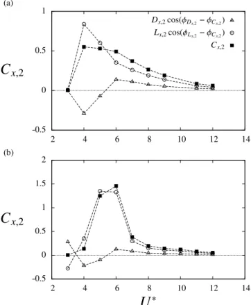
(13)The relative weights of the different terms in(13), issued from the present simulation results, are plotted inFig. 9, in the
CF and IL
+
CF cases. In the CF case (Fig. 9(a)), the lift-like contribution is clearly dominant, especially in the region of peak amplitudes of Cx,2. For U∗
=
4 and U∗=
5, the drag-like contribution is even negative: it tends to decrease the amplitude ofthe in-line force fluctuation. At higher reduced velocities, both contributions are positive but the relative contribution of Lxto
Cx,2remains larger than 70%. This result suggests that the large amplitude of the fluctuating in-line force noted inFig. 4(b) in
the CF case, is mainly related to the emergence of a lift-like contribution associated with the angle
α
. A comparable behavioris observed in the IL+CF case (Fig. 9(b)). A simple mechanism of interaction between the in-line and cross-flow motions
can be proposed: as the body moves in the cross-flow direction, a fluctuating lift-like component emerges and considerably
alters the amplitude of˜Cx, and the resulting in-line vibration, if the body is allowed to move in this direction. This may explain
why, in the intermediate range of U∗
, in-line oscillations appear when cross-flow oscillations occur.
Similarly, the cross-flow force coefficient Cycan be altered by the emergence of a drag-like contribution related to the
angle
α
. According to expression(12), the amplitude of the first harmonic of Cy(which dominates its spectrum) writesCy,1
=
Dy,1cos(φ
Dy,1−
φ
Cy,1)+
Ly,1cos(φ
Ly,1−
φ
Cy,1).
(14)An analysis of the relative weights of each term in(14)shows that the drag-like contribution to Cy,1is negligible.
4.2. Influence ofΨ
A simple model has been introduced in Section2.3to shed some light on the modulations of the fluid forces expressed
in the moving frame, due to the variation of the instantaneous flow velocity magnitude. Following this model, the time-averaged value of the force coefficient aligned with the instantaneous flow velocity can be expressed as
Cη
≈
(1−
κ
η)Cxf+
κ
ηCxfΨ+
1 2κ
ηCf
x,2cos(
φ
Ψ2−
φ
Cxf,2)Ψ2.
(15)In(15), Cηdepends on the time-averaged and fluctuating parts ofΨ(ΨandΨ2). However, as Cxf,2is generally small compared
to Cxf, the contribution of the term related toΨ is expected to dominate, especially whenΨ
≫
Ψ2. In this case, the modelsuggests a linear trend of CηversusΨ:
Cη
≈
Cxf+
κ
ηCxf(Ψ−
1).
(16)The evolution of Cηas a function ofΨ
−
1, issued from the simulations, is plotted inFig. 10(a). In this plot, the color of the176 S. Gsell, R. Bourguet and M. Braza / Journal of Fluids and Structures 85 (2019) 165–180
Fig. 9. Drag- and lift-like contributions to the fluctuating in-line force as functions of the reduced velocity: evolutions of the three terms in(13)in the (a)
CF and (b) IL+CF cases.
linear relation suggested by(16)is generally observed whenΨ
≫
Ψ2(dark-blue symbols). As shown inFig. 10(b), Cxisclosely connected to Cη. The increase of Cxobserved when the body oscillates in one or both directions (Fig. 4(a)) can thus
be related to the modulation of CηbyΨ.
The phenomenological model also suggests a trend for the fluid force normal to the instantaneous oncoming flow velocity,
Cξ. According to(9), the magnitude of the first harmonic can be expressed as follows:
Cξ,1
≈(1
−
κ
ξ)Cyf,1cos(φ
Cyf,1−
φ
Cξ,1)+
κ
ξCyf,1Ψcos(φ
Cf y,1−
φ
Cξ,1)+
1 2κ
ξC f y,1Ψ2sin(φ
Cξ,1−
φ
Ψ2+
φ
Cf y,1 ),
(17)where
φ
Cξ,1denotes the phase of the first harmonic of Cξ. The third term of(17)becomes negligible whenΨ≫
Ψ2. In thiscase, Cξ,1is expected to follow a linear evolution as a function ofΨ,
Cξ,1
≈
Cyf,1cos(φ
Cyf,1−
φ
Cξ,1)+
κ
ξCf
y,1cos(
φ
Cyf,1−
φ
Cξ,1)(Ψ−
1).
(18)The results reported inFig. 11(a), which are issued from the present simulations, globally confirm this trend forΨ
≫
Ψ2(dark-blue symbols).
As shown inFig. 11(b), the amplification of Cξ,1is generally accompanied by an increase of Cy,1. Therefore, the modulation
of Cξ,1 byΨ may play a role in the alteration of the cross-flow response when in-line oscillations occur. The structural
responses are often close to harmonic. For harmonic oscillations defined as
ζ
x=
ζ
x,2sin(4π
f1t+
φ
ζx,2),
(19a)ζ
y=
ζ
y,1sin(2π
f1t+
φ
ζy,1),
(19b)where
ζ
i,nare the spectral amplitudes andφ
ζi,nthe corresponding phases, the time-averaged value ofΨ is equal toΨ
=
1+
2π
2f12(
4
ζ
x2,2+
ζ
y2,1)
Bearman, P.W., 1984. Vortex shedding from oscillating bluff bodies. Annu. Rev. Fluid Mech. 16 (1), 195–222.
Bishop, R.E.D., Hassan, A.Y., 1964. The lift and drag forces on a circular cylinder oscillating in a flowing fluid. Proc. R. Soc. A 277 (1368), 51–75.
Blackburn, H.M., Govardhan, R.N., Williamson, C.H.K., 2001. A complementary numerical and physical investigation of vortex-induced vibration. J. Fluids Struct. 15 (3), 481–488.
Brika, D., Laneville, A., 1993. Vortex-induced vibrations of a long flexible circular cylinder. J. Fluid Mech. 250, 481–508.
Cagney, N., Balabani, S., 2013. Wake modes of a cylinder undergoing free streamwise vortex-induced vibrations. J. Fluids Struct. 38, 127–145. Cagney, N., Balabani, S., 2014. Streamwise vortex-induced vibrations of cylinders with one and two degrees of freedom. J. Fluid Mech. 758, 702–727. Dahl, J.M., Hover, F.S., Triantafyllou, M.S., Dong, S., Karniadakis, G.E., 2007. Resonant vibrations of bluff bodies cause multivortex shedding and high frequency
forces. Phys. Rev. Lett. 99 (14), 144503.
Dahl, J.M., Hover, F.S., Triantafyllou, M.S., Oakley, O.H., 2010. Dual resonance in vortex-induced vibrations at subcritical and supercritical reynolds numbers. J. Fluid Mech. 643, 395–424.
Feng, C.C., 1968. The measurement of vortex-induced effects in flow past stationary and oscillating circular and D-section cylinders (Master’s thesis), University of British Columbia.
Govardhan, R.N., Williamson, C.H.K., 2000. Modes of vortex formation and frequency response of a freely vibrating cylinder. J. Fluid Mech. 420, 85–130. Gsell, S., Bourguet, R., Braza, M., 2016. Two-degree-of-freedom vortex-induced vibrations of a circular cylinder at re = 3900. J. Fluids Struct. 67, 156–172. Hover, F.S., Techet, A.H., Triantafyllou, M.S., 1998. Forces on oscillating uniform and tapered cylinders in crossflow. J. Fluid Mech. 363, 97–114.
Huera-Huarte, F.J., Bearman, P.W., 2009. Wake structures and vortex-induced vibrations of a long flexible cylinder - part 1: dynamic response. J. Fluids Struct. 25 (6), 969–990.
Jauvtis, N., Williamson, C.H.K., 2004. The effect of two degrees of freedom on vortex-induced vibration at low mass and damping. J. Fluid Mech. 509, 23–62. Khalak, A., Williamson, C.H.K., 1997. Fluid forces and dynamics of a hydroelastic structure with very low mass and damping. J. Fluids Struct. 11 (8), 973–982. Khalak, A., Williamson, C.H.K., 1999. Motions, forces and mode transitions in vortex-induced vibrations at low mass-damping. J. Fluids Struct. 13 (7), 813–
851.
Leontini, J.S., Thompson, M.C., Hourigan, K., 2006. The beginning of branching behaviour of vortex-induced vibration during two-dimensional flow. J. Fluids Struct. 22 (6), 857–864.
Naudascher, E., 1987. Flow-induced streamwise vibrations of structures. J. Fluids Struct. 1 (3), 265–298. Navrose, Mittal, S., 2013. Free vibrations of a cylinder: 3-d computations at Re= 1000. J. Fluids Struct. 41, 109–118. Norberg, C., 2003. Fluctuating lift on a circular cylinder: review and new measurements. J. Fluids Struct. 17 (1), 57–96.
Okajima, A., Nakamura, A., Kosugi, T., Uchida, H., Tamaki, R., 2004. Flow-induced in-line oscillation of a circular cylinder. Eur. J. Mech. B Fluids 23 (1), 115–125.
Ouvrard, H., Koobus, B., Dervieux, A., Salvetti, M.V., 2010. Classical and variational multiscale les of the flow around a circular cylinder on unstructured grids. Comput. & Fluids 39 (7), 1083–1094.
Païdoussis, M.P., Price, S.J., de Langre, E., 2010. Fluid-Structure Interactions: Cross-Flow-Induced Instabilities. Cambridge University Press. Sarpkaya, T., 1978. Fluid forces on oscillating cylinders. ASCE J. Waterway, Port, Coaastal, Ocean Division 104, 275–290.
Sarpkaya, T., 2004. A critical review of the intrinsic nature of vortex-induced vibrations. J. Fluids Struct. 19 (4), 389–447.
Shiels, D., Leonard, A., Roshko, A., 2001. Flow-induced vibration of a circular cylinder at limiting structural parameters. J. Fluids Struct. 15 (1), 3–21. Vandiver, J.K., Jaiswal, V., Jhingran, V., 2009. Insights on vortex-induced, traveling waves on long risers. J. Fluids Struct. 25 (4), 641–653.
Wang, X.Q., So, R.M.C., Chan, K.T., 2003. A non-linear fluid force model for vortex-induced vibration of an elastic cylinder. J. Sound Vib. 260 (2), 287–305. Wieselsberger, C., 1922. New data on the laws of fluid resistance. In: Tech. Rep. National Advisory Comittee for Aeronautics.
Williamson, C.H.K., Govardhan, R.N., 2004. Vortex-induced vibrations. Annu. Rev. Fluid Mech. 36, 413–455.
Williamson, C.H.K., Roshko, A., 1988. Vortex formation in the wake of an oscillating cylinder. J. Fluids Struct. 2 (4), 355–381.