O
pen
A
rchive
T
OULOUSE
A
rchive
O
uverte (
OATAO
)
OATAO is an open access repository that collects the work of Toulouse researchers and
makes it freely available over the web where possible.
This is an author-deposited version published in :
http://oatao.univ-toulouse.fr/
Eprints ID : 16593
To link to this article : DOI :
10.1021/jp509080e
URL :
http://dx.doi.org/10.1021/jp509080e
To cite this version :
Kaperski, Anne and Weibel, Alicia and Datas,
Lucien and de Grave, Eddy and Peigney, Alain and Laurent,
Christophe Large-Diameter Single-Wall Carbon Nanotubes Formed
Alongside Small-Diameter Double-Walled Carbon Nanotubes.
(2015) The Journal of Physical Chemistry C, vol. 119, n°3 . pp.
1524-1535. ISSN 1932-7447
Any correspondence concerning this service should be sent to the repository
administrator:
[email protected]
Large-Diameter Single-Wall Carbon Nanotubes Formed Alongside
Small-Diameter Double-Walled Carbon Nanotubes
Anne Kasperski,
†Alicia Weibel,
†Lucien Datas,
†Eddy De Grave,
‡Alain Peigney,
†and Christophe Laurent*
,††Université de Toulouse, UMR UPS-CNRS-INPT, Institut Carnot CIRIMAT, Université Paul-Sabatier, 118 route de Narbonne,
31062 Toulouse cedex 9, France
‡Department of Physics and Astronomy, University of Ghent, Proeftuinstraat 86, B-9000 Gent, Belgium
*
S Supporting InformationABSTRACT: Samples containing a majority of either single-wall carbon nanotubes (SWCNTs) or double-walled carbon nanotubes (DWCNTs) are prepared in the same catalytic chemical vapor deposition conditions but using slightly different catalytic materials, based on alumina impregnated with iron and molybdenum salts. There is a sharp SWCNTs-to-DWCNTs transition. By contrast to the usualfindings, the selectivity is not correlated to the size of the iron-based catalyst nanoparticles, nor does the transition occur upon a decreasing carbon/catalyst ratio. The result is attributed to the increasing MoO3 concentration inducing modifications of the gas atmosphere, such as the formation of more reactive C2 species through C2H4 dissociation, which thus favors the nucleation and growth of a DWCNT. In the DWCNT sample, the average diameter of the SWCNTs is higher than the average outer diameter of the DWCNTs, which is uncommon, as many authors stress that SWCNTs show
a lower diameter than DWCNTs. The study could provide guidelines for the synthesis of very small diameter DWCNTs.
■
INTRODUCTIONDouble-walled carbon nanotubes (DWCNTs) are a unique class of CNTs, extremely interesting for scientific investigations and with a very high potential for technological applications.1,2 First, their coaxial structure makes them mechanically, thermally, and structurally more stable than single-wall CNTs (SWCNTs). Second, many applications require CNT function-alization in order to improve their ability toward dispersion or their compatibility with the external environment. Covalent functionalization in particular will partially damage the outer wall, resulting in drastic modifications in terms of both electrical and mechanical properties, which obviously is a serious drawback for SWCNTs. By contrast, the outer wall of DWCNTs can be modified while protecting the inner tube from any damage. For example, it was reported that the inner tubes of DWCNTs with small diameter are preferred over SWCNTs for producing photoluminescent materials3 and that functionalized DWCNTs are advantageous for CNT-based trans-membrane channels be-cause the shielding of the amphiphilic outer tube could guarantee biocompatibility of the synthetic channel and protect the inner tube (the functional part) from disturbance of the membrane environment.4Other results have revealed the potential of using covalently functionalized DWCNTs for simultaneous ultrahigh selective and sensitive detection of chemicals and performance comparison with devices based on SWCNTs and multiwall CNTs (MWCNTs) has illustrated some of the advantages of the DWCNT strategy to nanoelectronics.5 It was also found that, compared with an SWCNT bundle, a DWCNT bundle
interconnect can lead to a reduction of crosstalk-induced time delay, which is thought to confirm that the DWCNT bundle interconnect will be more suitable for the next generation of interconnect technology as compared with the SWCNT bundle counterpart.6A comparison of the reinforcement of epoxy-based composites by SWCNTs, DWCNTs or MWCNTs showed that the most significant improvements of strength, stiffness and fracture toughness were attained with functionalized-DWCNTs.7 Even without functionalization, the CNT-matrix interface bond-ing lowers the effective fracture strength in SWCNTs, due to formation of defects, but does not play a role in DWCNTs, having interwall coupling, which, despite being weaker than SWCNTs, are less prone to damage in the outer wall.8 For example, DWCNT−MgO composites show a toughness value twice higher than that measured for pure MgO because of DWCNT crack-bridging and pullout.9A study on the tribological properties of CNT−Cu composites revealed that the lubrication mechanisms involve ovalization and collapse of DWCNTs, which therefore retain their structural integrity, as opposed to shortening and exfoliation in the case of MWCNTs.10 A DWCNT-derived device is attractive for producing anode materials for lithium-ion batteries, although the cause of the large difference in the reversible capacity between SWCNT- and DWCNT-derived devices remains unclear.11The performance of
solar cells depends significantly on the type of CNTs, i.e., SWCNT-based cells show better performance under visible light illumination, whereas DWCNT-based solar cells exhibit high performance under infrared illumination.12 Therefore, there is a strong need for the selective synthesis of DWCNTs over SWCNTs and MWCNTS. Although they are sometimes considered as intermediate between SWCNTs and MWCNTs, DWCNTs are much closer to SWCNTs, notably regarding the formation mechanisms. DWCNTs can be prepared by the appropriate treatments of SWCNTs that contain fullerene peapods,13,14 but the extent of filling of the outer tube by the inner one is limited, and produced quantities are low. Catalytic chemical vapor deposition routes, where a carbonaceous gas is decomposed over nanoparticles, offers a better degree of control and higher yields.15 It is well established that the number of graphene layers formed on the catalyst nanoparticles in the early stages of the CNT nucleation controls the number of walls formed.16,17 It has been estimated that there is a threshold, around 5 nm, in the length of a SWCNT, beyond which it can grow very long.18 As long as this critical length is not reached, a second carbon cap sometimes called yarmulke16,19 can form underneath thefirst, spaced by roughly the interlayer spacing of graphite and forcing it to lift up by forming a tube whose open end remains chemisorbed to the catalytic particle, until at some point the simultaneous growth of the two walls starts. In suitable conditions, tubes with three walls are formed too. Purification methods20,21are efficient to selectively eliminate the SWCNTs and poorly organized carbon species from the samples, but they are tedious and tend to generate a unacceptably high weight loss. Thus, DWCNTs are produced alongside SWCNTs and fine-tuning the experimental conditions allows one to make DWCNTs the major product.19,22−31Results have been reported regarding the influence of the synthesis parameters such as catalytic material composition,32−36 catalyst particle size,24,37−43 carbon sourceflow rate,44−46and temperature.22−24,45 Con flict-ing results are reported, which is possibly due in part to the fact that the many experimental parameters are not independent. Moreover, some works rather deal with the control of the outer diameter, and, although there is a clear correlation with the number of walls in the case of MWCNTs,47it is not so for CNTs with less than about four walls. Nevertheless, the accepted requirements for the formation of DWCNTs preferentially to SWCNTs appear to be a larger catalyst particle and/or an increased carbon supply.35,36 In earlier works,23,27,31,34,48−54we proposed and developed a CNT synthesis route involving the reduction in H2−CH4(or C2H4) gas atmosphere of an Al2O3−
Fe2O3 solid solution (called the catalytic material) where
iron-based (α-Fe, γ-Fe/C, Fe3C) nanoparticles are formed in situ, at a temperature high enough for them to catalyze the hydrocarbon gas decomposition and act as a center for the CNT nucleation and growth. The so-obtained materials are thus CNT−(Fe/C)− Al2O3 composites, in the form of a powder or a foam. The
variation of the synthesis parameters, such as the addition of MoO3into the system, permitted us to progressively increase the
selectivity on the number of walls of the obtained CNTs. In the present work, we will use Al2O3−Fe2O3−MoO3 powders as
catalytic materials because we consider them to be good model materials for further progress. Anyfinding on the DWCNT-over-SWCNT selectivity will be applied to a system based on MgO (as opposed to Al2O3), because MgO is easy to dissolve by a mild
acidic treatment in order to obtain suspensions of undamaged, purified CNTs19,32,33,55−57as required for many applications. In this work, it is shown that there exists a sharp transition, around some
particular experimental conditions, where preferential formation of either SWCNTs or DWCNTs takes place, and, moreover, that in the latter case, large-diameter SWCNTs are formed alongside small-diameter DWCNTs. By contrast to the usual findings, the selectivity is not necessarily correlated to the size of the iron-based catalyst nanoparticles, and the SWCNTs-to-DWCNTs transition occurs upon a decreasing carbon/catalyst ratio.
■
EXPERIMENTAL SECTIONPreparation of the Catalytic Materials. The catalytic materials were prepared by the incipient wetness impregnation route. The volume of deionized water necessary to homo-geneously wet a sample of a commercialγ-Al2O3powder (Taimei
Chemicals Co. Ltd., 99.99%, 188 m2/g) without leading to any
supernatant was determined. The appropriate quantities of Fe(NO3)2·9H2O and (NH4)6Mo7O24·4H2O were dissolved in this volume of water, and the solution was poured onto a sample of γ-Al2O3 powder. The paste was hand-mixed, dried overnight in air at 60°C, ground manually, and the so-obtained powder was calcined in air (500 °C, 1 h) producing the “as-prepared” catalytic material. Samples with a different Fe/Al molar ratio (0.01, 0.02, 0.03, and 0.04) were prepared. They will be denoted G1, G2, G3, and G4 hereafter. The Fe/Mo molar ratio was fixed to 5 for all samples. The addition of different amounts of molybdenum to the Fe−Al2O3system was
investigated in an earlier study,34 which showed that the addition of a small amount of molybdenum first favors the formation of DWCNTs over that of SWCNTs and, second, activates smaller nanoparticles, thus producing smaller-diameter CNTs. Each“as-prepared” powder was divided into two batches. Thefirst series of samples were loaded in a silica reactor (inner diameter 56 mm, length of the heating zone 200 mm) and heated in argon (9 L/h) up to 800°C at 7.5 °C/min, then up to 850°C at 2.5 °C/min and cooled down to room temperature (5°C/min). They will be denoted G1A, G2A, G3A, and G4A hereafter.
Synthesis of Carbon Nanotubes. For the second series, the samples were heated in argon (9 L/h) up to 800 °C at 7.5 °C/min, then up to 850 °C at 2.5 °C/min and upon reaching this temperature C2H4and H2were introduced to give a C2H4−H2−Ar mixture (2.5, 60, and 37.5 mol %, respectively,
total flow rate 24 L/h). One hour dwell time was applied at 850°C. Cooling down to room temperature was performed in argon. The flowing gas was dried on P2O5, and its composi-tion was regulated by mass-flow controllers. The so-obtained CNT-containing composite powders will be denoted G1R, G2R, G3R, and G4R hereafter.
Characterization. The carbon content (Cn) in the
composite powders was measured by the flash combustion method with an accuracy of±2%. The specific surface area of the powders was measured by the Brunauer−Emmett−Teller (BET) method (Flow Sorb II 2300, Micrometrics) using nitrogen adsorption at liquid nitrogen temperature. This instrument gives a specific surface area value from one point (i.e., one adsorption pressure) and requires calibration. The reproducibility of the results was determined to be in the±3% range. Raman spectra were recorded at 632.82 nm (LabRAM 800, Jobin-Yvon) and were averaged on three spectra. The specimens were observed by field-emission-gun scanning electron microscopy (FESEM) (JSM 6700F, JEOL). The observations were performed with a tension of 5 kV and a work distance around 6 mm, using the in-lens detector. High-resolution transmission electron microscopy (HRTEM) was
performed with microscope (JEM 2100F, JEOL) operated at 200 kV. The magnification of the apparatus allowed one to clearly distinguish the walls of isolated CNTs, which were easily distinguished from other forms of carbon. Electron micro-diffraction and energy dispersive spectroscopy analysis were also performed. The samples were slightly sonicated in ethanol, and a drop of the suspension was deposited onto a holey carbon grid. X-ray diffraction (XRD) patterns were recorded in the range 20−80° (2θ) with a Bruker D4 Endeavor diffractrometer operating with Cu Kα radiation. Counts were
registered every 0.02° (2θ). Mössbauer spectra were collected at 298, 85, and/or 18 K using a spectrometer operating in constant acceleration mode with triangular reference signal. A
57Co (Rh) source was used. Accumulation of data was made in
1024 channels. The spectra were computer-analyzed in terms of model-independent distributions of hyperfine-parameter values, and numerical data quoted hereafter refer to maximum-probability values.58Isomer shifts are referenced with respect toα-Fe at 298 K.
■
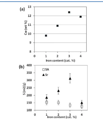
RESULTS AND DISCUSSIONThe carbon content in the GxR powders (Cn - Table 1 and Figure 1a) steadily increases from 9.8 wt % for G1R up to 12.4 wt % for G3R, reaching a plateau (11.9 wt % for G4R).
The specific surface area of the GxR powders (Sr- Table 1 and
Figure 1b) is higher than the specific surface area of the GxA powders (SA - Table 1 and Figure 1b). Sr doubles from G1R
(148 m2/g) to G3R (314 m2/g) but is much lower for G4R
(151 m2/g). As pointed out earlier,48,49,59it is the deposition of carbon in the composite powder, particularly in the form of CNTs, which is responsible for most of the supplementary surface area.
The high-frequency range (1100−1800 cm−1) of the Raman spectra (Figure 2) shows the D band (ca. 1328 cm−1) and the Table 1. Catalytic Materials Heat-Treated in Ar (GxA Powders): Specific Surface Area (SA); Reduced Specimens (GxR
Powders): Carbon Content in Weight (Cw), Specific Surface Area (Sr); ID/IGRatio; Average Diameter of the Metal Particles
(dm); Average Diameter of the SWCNTs (dSW); Average Inner Diameter of the DWCNTs (diDW); and Average Outer Diameter
of the DWCNTs (doDW)
catalytic material SA(m2/g) reduced specimen Cw(wt %) Sr(m2/g) ID/IG dm(nm) dSW(nm) diDW(nm) doDW(nm)
G1A 153 G1R 9.8 186 0.37 2.7 2.2 1.7 2.3
G2A 151 G2R 10.9 231 0.26 3.0 2.4 2.5 3.2
G3A 134 G3R 12.4 314 0.15 3.6 3.4 2.1 2.7
G4A 126 G4R 11.9 151 0.60 4.3 3.5 2.4 3.3
Figure 1.(a) The carbon content in the GxR powders and (b) the specific surface area of the GxA (SA) and GxR powders (Sr) versus the
iron content in the catalytic material.
Figure 2.Raman spectra of the (a) G1R, (b) G2R, (c) G3R, and (d) G4R powders. Insets: the low-frequency RBMs.
G band (ca. 1580 cm−1) but not the shoulder at higher frequency (ca. 1605 cm−1) typical of defective graphite-like materials and usually observed for MWCNTs.60 The ratio between the intensities of the D band and the G band, ID/IG
(Table 1), decreases from G1R to G3R (0.37 and 0.15, res-pectively) but is markedly higher for G4R (0.60). An increasing ID/IG value corresponds to a higher proportion of sp3-like
carbon, which is generally attributed to the presence of more structural defects. The presence of radial-breathing-modes (RBM) peaks in the low-frequency range (100−300 cm−1) of the spectrum (insets in Figure 2), the frequencies of which are inversely proportional to the CNT diameters, is usually the sign of the presence of small-diameter CNTs, such as SWCNTs and DCWNTs.61 Note that the Raman process is influenced by optical resonance, and it is thus impossible to detect all present CNTs using only one wavelength. Moreover, the peak inten-sities do not reflect the real amount of individual CNT because of the resonance effect, which amplifies the Raman signal from certain CNTs.
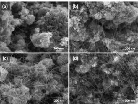
Field-emission gun scanning electron microscope (FEG-SEM) images of the GxR powders (Figure 3) reveal the presence of long,flexible filaments, with a smooth and regular surface, on the surface of the oxide grains and bridging several grains. No thick, short carbon nanofibers are observed. All filaments have a diameter lower than 30 nm and a length on the order of some tens of micrometers. From the results of previous studies,27it is known that suchfilaments are isolated CNTs and/or CNTs bundles.
Typical HRTEM images (Figure 4) show small-diameter SWCNTs and DWCNTs, either individual or in small bundles, along with alumina grains and metal nanoparticles (indicated by red and yellow arrows, respectively, on Figure 4a,b). Note that the latter could either be Fe, Fe/C alloy, or Fe carbide, as shown elsewhere34and as discussed later. The diameter of the nanoparticles is generally similar to that of the CNTs, although it is difficult to evaluate how many of them are actually linked to a CNT. A few large ones (>5 nm) have been imaged, mainly for G4R (Figure 4b). For G1R and G2R (Figure 4c), the CNTs
Figure 3.FEG-SEM images of the (a) G1R, (b) G2R, (c) G3R, and (d) G4R powders.
Figure 4.Typical TEM images of the (a) G1R and (b) G4R powders; typical HRTEM images of CNTs for (c) G1R or G2R and for (d,e) G3R or G4R.
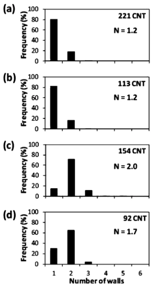
are mainly SWCNTs (diameter 0.8−4 nm - Figure 4c1−c5) and only a few DWCNTs (Figure 4c6), with a similar diam-eter, are also imaged. On the contrary, for G3R and G4R (Figure 4d), only a few SWCNTs are imaged (Figure 4d1), and most CNTs are DWCNTs (outer diameter 1.2−5 nm - Figure 4d2−d5). This sharp difference between G1R and G2R on one hand and G3R and G4R on the other hand is confirmed by data derived from measurements on tens of HRTEM images (Figure 5) in order to obtain more representative
information.23,56 For G1R (Figure 5a) and G2R (Figure 5b), there are only SWCNTs (80%) and DWCNTs (20%). By contrast, for G3R (Figure 5c) and G4R (Figure 5d), the DWCNTs form the majority (ca. 70%) in addition to SWCNTs and some triple-walled CNTs (3WCNTs). Due to the great length of the CNTs, only a few tips have been imaged, revealing that most are empty (Figure 4c2,e1−e4) in line with the yarmulke16,27or tangential18mechanisms, and only some of them contain a nanoparticle (Figure 4e5,e6), indicating tip-growth.62
The diameter distribution of the metal nanoparticles (Figure 6) slightly shifts toward higher sizes from G1R to G3R and is notably wider for G4R. The average diameter (dnp- Table 1)
increases from 2.7 to 4.3 nm and is higher than the average CNT outer diameter (do - Table 1), calculated from
measurements on HRTEM images of all CNTs, regardless of the number of walls (Figure 7). The difference increases from 0.5 nm (for G1R) to 1 nm (for G4R). This could reflect first that the proportion of the smaller nanoparticles (say, below 2 nm) is undervalued because they are more difficult to detect than the larger ones and, second, that the larger nanoparticles are not linked to a CNT, i.e., they were not active for the nucleation and growth of a CNT. Increasing the iron content
in the catalytic material increases the total number of nanoparticles, but it also increases their average diameter (Figure 7) and distribution width (Figure 6), so that the proportion of active nanoparticles tends to decrease. This is line with the corresponding increase in carbon content, lower than could be expected (Figure 1a). However, when a distinction is made between the average diameters of SWCNTs and
Figure 5.Distribution of the number of walls of the CNT for (a) G1R, (b) G2R, (c) G3R, and (d) G4R.
Figure 6.Distribution of the diameter of the metal (and/or carbide) nanoparticles for (a) G1R, (b) G2R, (c) G3R, and (d) G4R.
Figure 7.Average diameters versus the iron content in the catalytic material: metal nanoparticles (black), outer diameter of all measured CNTs (green), diameter of SWCNTs (blue), and outer diameters of DWCNTs (red).
DWCNTs (Figure 7), it is interesting to note that for G3R, the SWCNTs average diameter is 0.5 nm higher than the DWCNTs average diameter, which is clearly uncommon, as many authors stress that DWCNTs are larger than SWCNTs.19,28,29,45 This could be related to the transition in number of walls selectivity occurring between G2R and G3R (Figure 5b,c). A first hypothesis would be that this transition could reflect the higher proportion of larger nanoparticles. However, the diameter distributions in three classes (0−2, 2−4, and 4−6 nm) (Figure 8) reveal that the relative proportions of SWCNTs in the 0−2 and 2−4 nm classes, for G1R and G2R, are similar to the relative proportions of DWCNTs in these classes, for G3R and G4R. Thus, in a given sample, a size-class of nanoparticles is as much active for SWCNT formation as it is for DWCNT formation, and therefore this evidences that the SWCNT/DWCNT selectivity is not necessarily correlated to nanoparticle size.
The SWCNT/DWCNT transition could find its origin in changes that may occur in the catalytic material due to the increase in (iron + molybdenum) content. Analysis of the XRD patterns of the GxA powders (Figure S1) revealed only peaks corresponding to standard γ-Al2O3 (JCPDS card 29-1486).
MoO3is not detected because of the very low content,50and
free iron oxides are not detected either because of the low content or because the corresponding peaks, if present, would be masked by theγ-Al2O3peaks, or due to the formation of a γ-Fe2O3monolayer on the alumina surface or a γ-(Al/Fe)2O3
solid solution caused by the substitution of surface Al3+ ions
γ-Al2O3by Fe3+ions during the wet impregnation63or during
the thermal treatments in air and argon.64,65However, the iron contents involved are too low to detect a gradual shift of the γ-Al2O3 peaks toward lower diffraction angles, as could be
expected if Al3+ions were replaced in the lattice by the larger Fe3+ions.66,67
The GxA powders (as well as the GxR powders later in the text) were also studied by 57Fe Mössbauer spectroscopy. Indeed, the spectra and parameters derived from these are very
sensitive to electronic, magnetic, and structural characteristics of the probed material, and as such, Mössbauer spectroscopy is an extremely useful tool for phase identification and quantification of mixtures of Fe-bearing solid materials. It allows one to pre-cisely characterize the iron species in the Al2O3−Fe2O3−MoO3 catalytic material and how they may evolve during the CCVD treatments, in composition, size, and spatial distribution to eventually form the iron-based (α-Fe, γ-Fe/C, Fe3C) catalyst
nanoparticles, which may or may not be involved in CNT nucleation and growth. Hence the Mössbauer measurements do provide a relevant contribution to understanding the chemistry of the processes involved. The comparison of the Mössbauer spectroscopy results with other data (measured carbon content, particle diameter, CNT diameter, number of walls) provides many insights into the mechanisms of CNT formation and on the selectivity upon the number of wall in particular.23,50,51,53,54,56,57 The Mössbauer spectra for G2A, G3A, and G4A were recorded at room temperature and 18 K (Figure 9 and Table S1). All mea-surements were done using a narrow velocity scale (±4 mm/s), implying a higher resolution, except for G4A/18 K, for which a wider scale (±10 mm/s) was used in order to attempt detect-ing a possible magnetic component (Figure 9f). All spectra consist of a single Fe3+ doublet. The spectra were fitted with quadrupole-splitting distributions (QSDs) assuming a linear correlation between the isomer shift and quadrupole splitting, which will not be discussed here, similar spectra having been extensively discussed elsewhere.66 A Mössbauer spectroscopy study of similar specimens revealed that there is no interaction between iron- and molybdenum species34and, comparing with the data obtained for a γ-(Al/Fe)2O3 solid solution,67 could
indicate that the present doublet represents Fe3+ ions dis-tributed among the tetrahedral and octahedral lattice sites of γ-Al2O3, a defective spinel structure, thus revealing the
formation of a γ-(Al/Fe)2O3 solid solution. More specific details about the Fe3+-cation distribution in the spinel structure
cannot be concluded from the present spectra. However, it is not possible to rule out that the doublet represents very small
Figure 8.Distributions of the diameters of SWCNTs and DWCNTs in three classes, the frequencies being calculated from the total number of CNTs (SWCNTs + DWCNTs) for (a) G1R, (b) G2R), (c) G3R, and (d) G4R.
(<5 nm)α-Fe2O3(hematite) particles still superparamagnetic at
18 K.68−71For G4A/18 K, very faint signals at about±7.5 mm/s (arrows in Figure 9f) could correspond to the outer lines of a sextet characteristic of a magnetic component. For the sake of comparison, the Mössbauer spectrum was recorded at 18 K for G4, i.e., prior to the argon treatment at 850 °C (inset in Figure 9f). It is indeed necessary to include in thefitting model a sextet (Bhf = 45.1 T,δ = 0.50 mm/s, 2εQ = −0.08 mm/s,
relative area 42%) in addition to the doublet for the latter spec-trum. The hyperfine field is significantly too low to represent either α-Fe2O3(hematite) orγ-Fe2O3(maghemite) but could
account for amorphous Fe2O3 nanoparticles.
72
During the heating in argon, these nanoparticles would either crystallize into α-Fe2O3 nanoparticles, albeit still small and super-paramagnetic, or form aγ-(Al/Fe)2O3solid solution.
TEM observations for G3A (Figure 10a) and analysis of the corresponding electron microdiffraction pattern (Figure 10b) do not provide evidence for the presence of α-Fe2O3
nano-particles. This is confirmed by energy dispersive spectroscopy analysis, which shows that although some areas (Figure 10c) show a little excess iron, other areas (Figure 10d) show the expected values of nFe/nAl = 0.03 and nFe/nMo = 5 (Table S2).
Regarding the GxR powders, the XRD patterns (Figure S2) show the diffraction peaks of γ-Al2O3, with no significant difference from the parent GxA powders. No α-Al2O3 was detected. Reduced phases (Fe, Fe3C, Mo2C) are not detected
due to the overlapping with the diffractions peaks of γ-Al2O3
and/or low content.
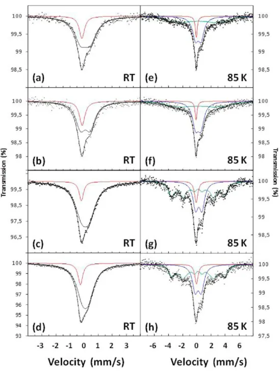
Mössbauer spectra were recorded at room temperature and 85 K for powders GxR (Figure 11 and Table 2) and also at 17 K for G4R (Figure S3). The room temperature spectra werefitted with two components: a singlet due to γ-Fe−C and another singlet whose origin is unclear. Interestingly, the evolution of their relative proportions (Figure 12a) shows a transition between G2R and G3R. For the Mössbauer spectra measured at 85 and 17 K, three components were found to be required to obtain adequatefits: (i) a singlet due to γ-Fe/C, (ii) a sextet that can be ascribed to ferromagnetic cementite (Fe3C), and
(iii) a doublet whose origin is unclear. Interestingly, noα-Fe was found. However, their relative proportions (Figure 12b) do
Figure 9.Mössbauer spectra measured at room temperature or 18 K: G2A (a, d), G3A (b,e) and G4A (c,f). Inset in panel f: the 18 K spectrum of G4.
Figure 10. (a) TEM image of G3A and (b) the corresponding electron microdiffraction pattern; (c,d) selected areas for energy dispersive spectroscopy analysis (see Table S2).
Figure 11.Mössbauer spectra at room temperature or 85 K for G1R (a,e), G2R (b,f), G3R (c,g), and G4R (d,h).
Table 2. Mössbauer Parameters of the GxR Powders
sextet singlet 1 singlet/doublet
sample Bhfa(T) 2ϵQb(mm/s) δc(mm/s) RAd(%) δ (mm/s) RA (%) ΔEQ,me(mm/s) δ (mm/s) RA (%) RT G1R - - - - −0.07 56 0 0.56 44 G2R - - - - −0.10 55 0 0.41 45 G3R - - - - −0.13 34 0 0.34 66 G4R - - - - −0.15 31 0 0.30 69 85 K G1R 23.9 −0.04 0.31f 45 0.02 13 0.80 0.42 42 G2R 23.8 −0.04 0.31f 47 −0.04 15 0.67 0.54 37 G3R 23.7 −0.02 0.30 55 −0.03 11 0.81 0.45 33 G4R 24.6 0.00 0.31 53 −0.08 15 0.66 0.49 32 17 K G4R 24.4 −0.03 0.37 75 0.02f 5 0.94 0.32 21
not show a transition between G2R and G3R: the singletγ-Fe/C is constant (11−15%), the Fe3C sextet slightly increases, and
the unknown doublet slightly decreases upon the increase in iron content. It was not possible to unambiguously identify the specie(s) responsible for the room temperature (RT) singlet and 85 K doublet, and this will be the aim of future studies.
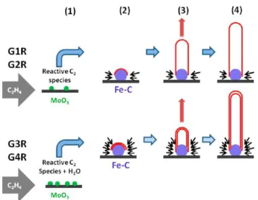
Finally, the present authors propose a schematic description of the mechanisms for the preferential nucleation and growth of either SWCNTs or DWCNTs and the sharp transition (Figure 13), which depends on the respective strength of several phenomena. The increase of the size of the metal (catalyst) nanoparticles does not appear to be the key parameter. There is no interaction between the MoO3species and the iron species in the catalytic material, but the increasing MoO3 concentration
induces some modifications of the gas atmosphere,50,73 in particular C2H4 dissociation. This is believed to result in the
formation of more reactive C2species,74which would favor the formation of two caps on the surface of a nanoparticle, and thus the nucleation and growth of a DWCNT. This is in competition with a decreasing carbon/catalyst ratio, both at the macroscopic scale, with an increased (iron + molybdenum) amount for an unchanged C2H4 supply and at the microscopic scale, with an
important increase in the number of nanoparticles and thus in active surface area. Moreover, the H2 reduction of MoO3 into
Mo2C forms H2O, which could etch away carbon precipitates
covering the metal nanoparticles,66,72 leading to cleaner and more active nanoparticles, preferentially producing DWCNTs with fewer defects, in agreement with the results obtained by Raman spectroscopy.
■
CONCLUSIONSThis study shows that, under applied experimental conditions, small changes in the composition of the catalytic material result in a sharp transition between the preferential formation of SWCNTs or DWCNTs. In contrast to the usualfindings, the selectivity is not necessarily correlated to the size of the iron-based (γ-Fe/C, Fe3C) catalyst nanoparticles. Indeed, in a given sample, a nanoparticles size-class is as much active for SWCNT formation as it is for DWCNT formation. Again in contrast to other works, the SWCNTs-to-DWCNTs transition occurs upon a decreasing carbon/catalyst ratio. The result is explained by another phenomenon that appears to be stronger in these conditions: the increasing MoO3 concentration induces some modifications of the gas atmosphere, first C2H4 dissociation
resulting in the formation of more reactive C2 species, and second the formation of H2O, which could etch away carbon
precipitates covering the metal nanoparticles, which both favor the formation of two caps on the surface of a nanoparticle and thus the nucleation and growth of a DWCNT with few defects. Interestingly, in the DWCNT sample, the average diameter of the SWCNTs is 0.5 nm higher than the average outer diameter of the DWCNTs, which is clearly uncommon, as many authors stress that SWCNTs show a smaller diameter than DWCNTs. The results obtained in this study provide further information for the precise control of the number of walls of CNTs and could provide guidelines for the synthesis of very small diameter DWCNTs, whose optical and mechanical properties are interesting.
■
ASSOCIATED CONTENT*
S Supporting InformationXRD patterns of the GxA and GxR powders, results of Energy Dispersive Spectroscopy analysis, the57Fe Mössbauer spectrum
of G4R measured at 17 K, and Mössbauer parameters of the GxA powders room temperature and 17 K. This material is available free of charge via the Internet at http://pubs.acs.org.
Figure 12.Relative area of the Mössbauer components versus the iron content in the catalytic material. (a) Spectra measured at room temperature: singlet 1 (red) and singlet 2 (black); (b) spectra measured at 85 K: singlet 1 (red), doublet (blue), and sextet (green).
Figure 13. Schematic description of the mechanisms for the preferential nucleation and growth of either SWCNTs or DWCNTs.
■
AUTHOR INFORMATIONCorresponding Author
*Phone +33 561 55 61 22; Fax +33 561 55 61 63; e-mail [email protected].
Notes
The authors declare no competingfinancial interest.
■
ACKNOWLEDGMENTSElectron microscopy observations were performed at TEMSCAN, the “Service Commun de Microscopie Electronique à Trans-mission”, Université Paul Sabatier (UPS), Toulouse. A.K. thanks UPS for the ATUPS grant.
■
REFERENCES(1) Pfeiffer, R.; Pichler, T.; Kim, Y. A.; Kuzmany, H. Double-Wall Carbon Nanotubes. Top. Appl. Phys. 2008, 111, 495−530.
(2) Kim, Y. A.; Yang, K. S.; Muramatsu, H.; Hayashi, T.; Endo, M.; Terrones, M.; Dresselhaus, M. S. Double-Walled Carbon Nanotubes: Synthesis, Structural Characterization, and Application. Carbon Lett. 2014, 15, 77−88.
(3) Hertel, T.; Hagen, A.; Talalaev, V.; Arnold, K.; Hennrich, F.; Kappes, M.; Rosenthal, S.; McBride, J.; Ulbricht, H.; Flahaut, E. Spectroscopy of Single- and Double-Wall Carbon Nanotubes in Different Environments. Nano Lett. 2005, 5, 511−514.
(4) Li, X.; Liu, B.; Yang, Y.; Zhao, Y. Carbon Nanotube Based Artificial Water Channel Protein: Membrane Perturbation and Water Transportation. Nano Lett. 2009, 9, 1386−1394.
(5) Huang, J.; Ng, A. L.; Piao, Y.; Chen, F.; Green, A. A.; Sun, C.-F.; Hersam, M. C.; Lee, C. S.; Wang, Y. Covalently Functionalized Double-Walled Carbon Nanotubes Combine High Sensitivity and Selectivity in the Electrical Detection of Small Molecules. J. Am. Chem. Soc. 2013, 135, 2306−2312.
(6) Pu, S.-N.; Yin, W.-Y.; Mao, J.-F.; Liu, Q. H. Crosstalk Prediction of Single- and Double-Walled Carbon-Nanotube (SWCNT/ DWCNT) Bundle Interconnects. IEEE Trans. Electron Devices 2009, 56, 560−568.
(7) Gojny, F. H.; Wichmann, M. H. G.; Fiedler, B.; Schulte, K. Influence of Different Carbon Nanotubes on the Mechanical Properties of Epoxy Matrix Composites - A Comparative Study. Compos. Sci. Technol. 2005, 65, 2300−2313.
(8) Pavia, F.; Curtin, W. A. Molecular Modeling of Cracks at Interfaces in Nanoceramic Composites. J. Mech. Phys. Solids 2013, 61, 1971−1982.
(9) Peigney, A.; Legorreta Garcia, F.; Estournès, C.; Weibel, A.; Laurent, Ch. Toughening and Hardening in Double-Walled Carbon Nanotube/Nanostructured Magnesia Composites. Carbon 2010, 48, 1952−1960.
(10) Guiderdoni, Ch.; Pavlenko, E.; Turq, V.; Weibel, A.; Puech, P.; Estournès, C.; Peigney, A.; Bacsa, W.; Laurent, Ch. The Preparation of Cu-matrix Composites Containing Carbon Nanotubes with a Different Number of Walls and Their Hardness, Friction and Wear Properties. Carbon 2013, 58, 185−197.
(11) Kim, Y. A.; Kojima, M.; Muramatsu, H.; Umemoto, S.; Watanabe, T.; Yoshida, K.; Sato, K.; Ikeda, T.; Hayashi, T.; Endo, M.; Terrones, M.; Dresselhaus, M. S. In Situ Raman Study on Single- and Double-Walled Carbon Nanotubes as a Function of Lithium Insertion. Small 2006, 2, 667−676.
(12) Xu, K.; Li, Y.; Yang, F.; Yang, W.; Zhang, L.; Xu, C.; Kaneko, T.; Hatakeyama, R. Controllable Synthesis of Single- and Double-Walled Carbon Nanotubes from Petroleum Coke and Their Application to Solar Cells. Carbon 2014, 68, 511−519.
(13) Smith, B. W.; Luzzi, D. E. Formation Mechanism of Fullerene Peapods and Coaxial Tubes: A Path to Large Scale Synthesis. Chem. Phys. Lett. 2000, 321, 169−174.
(14) Bandow, S.; Takizawa, M.; Hirahara, K.; Yudasaka, M.; Iijima, S. Raman Scattering Study of Double-Wall Carbon Nanotubes Derived
from the Chains of Fullerenes in Single-Wall Carbon Nanotubes. Chem. Phys. Lett. 2001, 337, 48−54.
(15) Jourdain, V.; Bichara, C. Current Understanding of the Growth of Carbon Nanotubes in Catalytic Chemical Vapour Deposition. Carbon 2013, 58, 2−39.
(16) Dai, H. J.; Rinzler, A. G.; Nikolaev, P.; Thess, A.; Colbert, D. T.; Smalley, R. E. Single-Wall Nanotubes Produced by Metal-Catalyzed Disproportionation of Carbon Monoxide. Chem. Phys. Lett. 1996, 260, 471−475.
(17) Sharma, R.; Rez, P.; Brown, M.; Du, G.; Treacy, M. M. J. Dynamic Observations of the Effect of Pressure and Temperature Conditions on the Selective Synthesis of Carbon Nanotubes. Nanotechnology 2007, 18, 126601−125608.
(18) Fiawoo, M. F. C.; Bonnot, A. M.; Amara, H.; Bichara, C.; Thibault-Penisson, J.; Loiseau, A. Evidence of Correlation between Catalyst Particles and the Single-Wall Carbon Nanotube Diameter: A First Step Towards Chirality Control. Chem. Phys. Lett. 2012, 108, 195503.1−195503.5.
(19) Flahaut, E.; Bacsa, R.; Peigney, A.; Laurent, C. Gram-Scale CCVD Synthesis of Double-Walled Carbon Nanotubes. Chem. Commun. 2003, 1442−1443.
(20) Endo, M.; Muramatsu, H.; Hayashi, T.; Kim, Y. A.; Terrones, M.; Dresselhaus, M. S. Nanotechnology:‘Buckypaper’ from Coaxial Nanotubes. Nature 2005, 433, 476.
(21) Osswald, S.; Flahaut, E.; Gogotsi, Y. In Situ Raman Spectroscopy Study of Oxidation of Double- and Single-Wall Carbon Nanotubes. Chem. Mater. 2006, 18, 1525−1533.
(22) Hafner, J. H.; Bronikowski, M. J.; Azamian, B. R.; Nikolaev, P.; Rinzler, A. G.; Colbert, D. T.; Smith, K. A.; Smalley, R. E. Catalytic Growth of Single-Wall Carbon Nanotubes from Metal Particles. Chem. Phys. Lett. 1998, 296, 195−202.
(23) Peigney, A.; Coquay, P.; Flahaut, E.; Vandenberghe, R. E.; De Grave, E.; Laurent, C. A Study of the Formation of Single- and Double-Walled Carbon Nanotubes by a CVD Method. J. Phys. Chem. B 2001, 105, 9699−9710.
(24) Cheung, C. L.; Kurtz, A.; Park, H.; Lieber, C. M. Diameter-Controlled Synthesis of Carbon Nanotubes. J. Phys. Chem. B 2002, 106, 2429−2433.
(25) Ren, W. C.; Li, F.; Chen, J. A.; Bai, S.; Cheng, H. M. Morphology, Diameter Distribution and Raman Scattering Measure-ments of Double-Walled Carbon Nanotubes Synthesized by Catalytic Decomposition of Methane. Chem. Phys. Lett. 2002, 359, 196−202.
(26) Li, W. Z.; Wen, J. G.; Sennett, M.; Ren, Z. F. Clean Double-Walled Carbon Nanotubes Synthesized by CVD. Chem. Phys. Lett. 2003, 368, 299−306.
(27) Flahaut, E.; Peigney, A.; Laurent, C. Double-Walled Carbon Nanotubes in Composite Powders. J. Nanosci. Nanotechnol. 2003, 3, 151−158.
(28) Lyu, S. C.; Lee, T. J.; Yang, C. W.; Lee, C. J. Synthesis and Characterization of High-Quality Double-Walled Carbon Nanotubes by Catalytic Decomposition of Alcohol. Chem. Commun. 2003, 1404− 1405.
(29) Liu, B. C.; Lyu, S. C.; Lee, T. J.; Choi, S. K.; Eum, S. J.; Yang, C. W.; Park, C. Y.; Lee, C. J. Synthesis of Single- and Double-Walled Carbon Nanotubes by Catalytic Decomposition of Methane. Chem. Phys. Lett. 2003, 373, 475−479.
(30) Zhu, J.; Yudasaka, M.; Iijima, S. A Catalytic Chemical Vapor Deposition Synthesis of Double-Walled Carbon Nanotubes over Metal Catalysts Supported on a Mesoporous Material. Chem. Phys. Lett. 2003, 380, 496−502.
(31) Laurent, C.; Peigney, A.; Flahaut, E.; Rousset, A. Synthesis of carbon nanotubes-Fe-Al2O3 powders. Influence of the characteristics
of the starting Al1.8Fe0.2O3oxide solid solution. Mater. Res. Bull. 2000,
35, 661−673.
(32) Flahaut, E.; Peigney, A.; Bacsa, W. S.; Bacsa, R. R.; Laurent, C. CCVD Synthesis of Carbon Nanotubes from (Mg,Co,Mo)O Catalysts: Influence of the Proportions of Cobalt and Molybdenum. J. Mater. Chem. 2004, 14, 646−653.
(33) Flahaut, E.; Laurent, C.; Peigney, A. Catalytic CVD Synthesis of Double and Triple-Walled Carbon Nanotubes by the Control of the Catalyst Preparation. Carbon 2005, 43, 375−383.
(34) Cordier, A.; de Resende, V. G.; De Grave, E.; Peigney, A.; Laurent, C. CCVD Synthesis of Single- and Double-Walled Carbon Nanotubes: Influence of the Addition of Molybdenum to Fe-Al2O3
Self-Supported Foams. J. Phys. Chem. C 2008, 112, 18825−18831. (35) Cui, C. J.; Qian, W. Z.; Zheng, C.; Liu, Y.; Yun, S.; Yu, Y. T.; Nie, J. Q.; Wei, F. Formation Mechanism of Carbon Encapsulated Fe Nanoparticles in the Growth of Single-/Double-Walled Carbon Nanotubes. Chem. Eng. J. 2013, 223, 617−622.
(36) Yang, H. S.; Zhang, L.; Dong, X. H.; Zhu, W. M.; Zhu, J.; Nelson, B. J.; Zhang, X. B. Precise Control of the Number of Walls Formed During Carbon Nanotube Growth Using Chemical Vapor Deposition. Nanotechnology 2012, 23, 065604.1−065604−6.
(37) Ago, H.; Nakamura, K.; Imamura, S.; Tsuji, M. Growth of Double-Wall Carbon Nanotubes with Diameter-Controlled Iron Oxide Nanoparticles Supported on MgO. Chem. Phys. Lett. 2004, 391, 308−313.
(38) Yamada, T.; Namai, T.; Hata, K.; Futaba, D. N.; Mizuno, K.; Fan, J.; Yudasaka, M.; Yumura, M.; Iijima, S. Size-Selective Growth of Double-Walled Carbon Nanotube Forests from Engineered Iron Catalysts. Nat. Nanotechnol. 2006, 1, 131−136.
(39) Ruemmeli, M. H.; Kramberger, C.; Loeffler, M.; Jost, O.; Bystrzejewski, M.; Grueneis, A.; Gemming, T.; Pompe, W.; Buechner, B.; Pichler, T. Catalyst Volume to Surface Area Constraints for Nucleating Carbon Nanotubes. J. Phys. Chem. B 2007, 111, 8234− 8241.
(40) Schaeffel, F.; Ruemmeli, M. H.; Kramberger, C.; Queitsch, U.; Mohn, E.; Kaltofen, R.; Pichler, T.; Buechner, B.; Rellinghaus, B.; Schultz, L. Tailoring the Diameter, Density and Number of Walls of Carbon Nanotubes through Predefined Catalyst Particles. Phys. Stat.us Solidi A 2008, 205, 1382−1385.
(41) Dervishi, E.; Li, Z.; Watanabe, F.; Xu, Y.; Saini, V.; Biris, A. R.; Biris, A. S. Thermally Controlled Synthesis of Single-Wall Carbon Nanotubes with Selective Diameters. J. Mater. Chem. 2009, 19, 3004− 3012.
(42) Dervishi, E.; Li, Z. R.; Watanabe, F.; Courte, A.; Biswas, A.; Biris, A. R.; Saini, V.; Xu, Y.; Biris, A. S. Versatile Catalytic System for the Large-Scale and Controlled Synthesis of Single-Wall, Double-Wall, Multi-Wall, and Graphene Carbon Nanostructures. Chem. Mater. 2009, 21, 5491−5498.
(43) Xie, R.; Zhong, G.; Zhang, C.; Chen, B.; Esconjauregui, C. S.; Robertson, J. Diameter and Wall Number Control of Carbon Nanotubes by Chemical Vapor Deposition. J. Appl. Phys. 2013, 114, 244302.1−244302.5.
(44) Zhang, H.; Cao, G. P.; Wang, Z. Y.; Yang, Y. S.; Shi, Z. J.; Gu, Z. N. Influence of Ethylene and Hydrogen Flow Rates on the Wall Number, Crystallinity, and Length of Millimeter-Long Carbon Nanotube Array. J. Phys. Chem. C 2008, 112, 12706−12709.
(45) Baliyan, A.; Hayasaki, Y.; Fukuda, T.; Uchida, T.; Nakajima, Y.; Hanajiri, T.; Maekawa, T. Precise Control of the Number of Walls of Carbon Nanotubes of a Uniform Internal Diameter. J. Phys. Chem. C 2013, 117, 683−686.
(46) Kobayashi, K.; Shukla, B.; Ohmori, S.; Kiyomiya, M.; Hirai, T.; Kuwahara, Y.; Saito, T. Wall-Number Selectivity in Single/Double-Wall Carbon Nanotube Production by Enhanced Direct Injection Pyrolytic Synthesis. Jpn. J. Appl. Phys. 2013, 52, 105102.1−105102.6. (47) Chiodarelli, N.; Richard, O.; Bender, H.; Heyns, M.; De Gendt, S.; Groeseneken, G.; Vereecken, P. M. Correlation between Number of Walls and Diameter in Multiwall Carbon Nanotubes Grown by Chemical Vapor Deposition. Carbon 2012, 50, 1748−1752.
(48) Peigney, A.; Laurent, C.; Dobigeon, F.; Rousset, A. Carbon Nanotubes Grown in Situ by a Novel Catalytic Method. J. Mater. Res. 1997, 12, 613−615.
(49) Peigney, A.; Laurent, C.; Rousset, A. Influence of the Composition of a H2-CH4 Gas Mixture on the Catalytic Synthesis
of Carbon Nanotubes-Fe/Fe3C-Al2O3 Nanocomposite Powders. J.
Mater. Chem. 1999, 9, 1167−1177.
(50) Cordier, A.; de Resende, V. G.; Weibel, A.; De Grave, E.; Peigney, A.; Laurent, C. Catalytic Chemical Vapor Deposition Synthesis of Double-Walled and Few-Walled Carbon Nanotubes by Using a MoO3-Supported Conditioning Catalyst to Control the
Formation of Iron Catalytic Particles within an α-Al1.8Fe0.2O3
Self-Supported Foam. J. Phys. Chem. C 2010, 114, 19188−19193. (51) de Resende, V. G.; Cordier, A.; De Grave, E.; Weibel, A.; Peigney, A.; da Costa, G. M.; Laurent, C.; Vandenberghe, R. E. Synthesis ofγ-(Al1−xFex)2O3Solid Solutions from Oxinate Precursors
and Formation of Carbon Nanotubes from the Solid Solutions Using Methane or Ethylene as Carbon Source. J. Mater. Res. 2008, 23, 3096− 3111.
(52) Laurent, Ch.; Peigney, A.; Rousset, A. Synthesis of Carbon Nanotubes-Fe-Al2O3Nanocomposite Powders by Selective Reduction
of Different Al1.8Fe0.2O3 Solid Solutions. J. Mater. Chem. 1998, 8,
1263−1271.
(53) de Resende, V. G.; De Grave, E.; Peigney, A.; Laurent, Ch. Surface Composition of Carbon Nanotubes-Fe-Alumina Nano-composite Powders: An Integral Low-Energy Electron Mössbauer Spectroscopic Study. J. Phys. Chem. C 2008, 112, 5756−5761.
(54) de Resende, V. G.; De Grave, E.; Cordier, A.; Weibel, A.; Peigney, A.; Laurent, Ch. Catalytic Chemical Vapor Deposition Synthesis of Single- and Double-Walled Carbon Nanotubes from α-(Al1−xFex)2O3Powders and Self-Supported Foams. Carbon 2009, 47,
482−492.
(55) Flahaut, E.; Peigney, A.; Laurent, Ch.; Rousset, A. Synthesis of Single-Walled Carbon Nanotubes-Co-MgO Composite Powders and Extraction of the Nanotubes. J. Mater. Chem. 2000, 10, 249−252.
(56) Coquay, P.; Peigney, A.; De Grave, E.; Vandenberghe, R. E.; Laurent, C. Carbon Nanotubes by a CVD Method. Part I: Formation of Nanotubes from (Mg, Fe)O Catalysts. J. Phys. Chem. B 2002, 106, 13199−13210.
(57) Coquay, P.; A. Peigney, A.; De Grave, E.; Flahaut, E.; Vandenberghe, R. E.; Laurent, Ch. Fe/Co Alloys for the CCVD Synthesis of Single- and Double-Walled Carbon Nanotubes - Part I: The CNT-Fe/Co-MgO System. J. Phys. Chem. B 2005, 109, 17813− 17824.
(58) Vandenberghe, R. E.; De Grave, E.; de Bakker, P. M. A. On the methodology of the analysis of Mossbauer spectra. Hyperfine Interact. 1994, 83, 29−49.
(59) Peigney, A.; Laurent, C.; Flahaut, E.; Bacsa, R. R.; Rousset, A. Specific Surface Area of Carbon Nanotubes and Bundles of Carbon Nanotubes. Carbon 2001, 39, 507−514.
(60) Jorio, A.; Pimenta, M. A.; Souza, A. G.; Saito, R.; Dresselhaus, G.; Dresselhaus, M. S. Characterizing Carbon Nanotube Samples with Resonance Raman Scattering. New J. Phys. 2003, 5, 139.1−139.17.
(61) Bacsa, R. R.; Flahaut, E.; Laurent, C.; Peigney, A.; Aloni, S.; Puech, P.; Bacsa, W. S. Narrow Diameter Double-Wall Carbon Nanotubes: Synthesis, Electron Microscopy and Inelastic Light Scattering. New. J. Phys. 2003, 5, 131.1−131.9.
(62) Amelinckx, S.; Bernaerts, D.; Zhang, X. B.; Van Tendeloo, G.; Van Landuyt, J. A Structure Model and Growth-Mechanism for Multishell Carbon Nanotubes. Science 1995, 267, 1334−1338.
(63) Feng, G.; Huo, C. F.; Li, Y. W.; Wang, J. G.; Jiao, H. J. Structures and Energies of Iron Promoted γ-Al2O3 Surface: A
Computational Study. Chem. Phys. Lett. 2011, 510, 224−227. (64) Kobayashi, Y.; Kawashima, D.; Tomita, A. Preparation of a γ-Alumina Film Doped with Fine γ-Iron(III) Oxide Particles. Chem. Mater. 1997, 9, 1887−1892.
(65) Zhong, Z. Y.; Prozorov, T.; Felner, I.; Gedanken, A. Sonochemical Synthesis and Characterization of Iron Oxide Coated on Submicrospherical Alumina: A Direct Observation of Interaction between Iron Oxide and Alumina. J. Phys. Chem. B 1999, 103, 947− 956.
(66) Hata, K.; Futaba, D. N.; Mizuno, K.; Namai, T.; Yumura, M.; Iijima, S. Water-Assisted Highly Efficient Synthesis of Impurity-Free Single-Waited Carbon Nanotubes. Science 2004, 306, 1362−1364.
(67) Gallegos, N. G.; Alvarez, A. M.; Cagnoli, M. V.; Bengoa, J. F.; Marchetti, S. G.; Mercader, R. C.; Yeramian, A. A. Selectivity to
Olefins of Fe/SiO2-MgO Catalysts in the Fischer−Tropsch Reaction.
J. Catal. 1996, 161, 132−142.
(68) Boudart, M.; Delbouille, A.; Dumesic, J. A.; Khammouma, S.; Topsoe, H. Surface, Catalytic and Magnetic-Properties of Small Iron Particles 0.1. Preparation and Characterization of Samples. J. Catal. 1975, 37, 486−502.
(69) Raupp, G. B.; Delgass, W. N. Mossbauer Investigation of Supported Fe and FeNi Catalysts 0.1. Effect of Pretreatment on Particle-Size. J. Catal. 1979, 58, 337−347.
(70) Kündig, W.; Bömmel, H.; Constabaris, G.; Lindquist, R. H. Some Properties of Supported Small α-Fe2O3 Particles Determined
with the Mössbauer Effect. Phys. Rev. 1966, 142, 327−333.
(71) Machala, L.; Zboril, R.; Gedanken, A. Amorphous Iron(III) Oxide - A Review. J. Phys. Chem. B 2007, 111, 4003−4018.
(72) Yoshihara, N.; Ago, H.; Tsuji, M. Chemistry of Water-Assisted Carbon Nanotube Growth over Fe-Mo/MgO Catalyst. J. Phys. Chem. C 2007, 111, 11577−11582.
(73) Franklin, N. R.; Dai, H. An Enhanced CVD Approach to Extensive Nanotube Networks with Directionality. Adv. Mater. 2000, 12, 890−894.
(74) Liu, Y. F.; Wongwiriyapan, W.; Park, K. C.; Muramatsu, H.; Takeuchi, K.; Kim, Y. A.; Endo, M. Combined Catalyst System for Preferential Growth of Few-Walled Carbon Nanotubes. Carbon 2009, 47, 2543−2546.