O
pen
A
rchive
T
OULOUSE
A
rchive
O
uverte (
OATAO
)
OATAO is an open access repository that collects the work of Toulouse researchers and
makes it freely available over the web where possible.
This is an author-deposited version published in :
http://oatao.univ-toulouse.fr/
Eprints ID : 17019
The contribution was presented at PIMRC 2016 :
http://ieee-pimrc.org/
To cite this version :
Despaux Rossi, François and Jaffres-Runser, Katia and Van
den Bossche, Adrien and Val, Thierry Accurate and Platform-agnostic
Time-of-flight Estimation in Ultra-Wide Band. (2016) In: 27th annual IEEE International
Conference on Personal, Indoor and Mobile Radio Communications (PIMRC
2016), 4 September 2016 - 7 September 2016 (Valencia, Spain).
Any correspondence concerning this service should be sent to the repository
administrator:
[email protected]
Accurate and Platform-agnostic Time-of-flight
Estimation in Ultra-Wide Band
Franc¸ois Despaux, Katia Jaffr`es-Runser, Adrien van den Bossche, Thierry Val
Institut de Recherche en Informatique de Toulouse
Universit´e de Toulouse, CNRS, INPT, UPS, UT1, UT2J
Email:
{francois.despaux, katia.jaffres-runser, vandenbo, val}@irit.fr
Abstract—Emerging applications of Ultra-Wide Band (UWB) combine low to medium rate communications with positioning capabilities allowing centimeter level accuracy in ranging. For positioning systems employing UWB radios, time-based schemes provide very good accuracy due to the high time resolution of UWB signals. These time-based positioning systems rely on measurements of travel times of signal between nodes allowing to estimate the distance between nodes. The standard IEEE 802.15.4a-2007 propose TWR and SDS-TWR time-based pro-tocols for ranging purpose. However, the accuracy of TWR is quite poor due to the effects of clock skews. SDS-TWR mitigates the clock skew error at the expenses of the number of message exchanges, which is increased. In this work, we present a novel approach for accurately estimating the ToF in UWB taking into account the clock skew between nodes while minimising the number of exchanged messages. Experimentations were carried out in our Open Source Framework, which enables fast prototyping of protocols based on an UWB Physical Layer.
Index Terms—Ranging; Ultra-Wide Band; Localisation; Wire-less Sensor Network
I. INTRODUCTION
Increasing attention and interest has been drawn lately to wireless positioning systems, specially for indoor conditions where Global Positioning Systems (GPS) are not available. Systems based on radio frequency signals (RF) require a simpler infrastructure than other technologies but at the cost of a reduced accuracy. This accuracy is of several meters using WiFi [6], ZigBee [1] or in the order of tens of meters for mobile networks [3]. However, such precision is unacceptable for applications with centimetre-level accuracy requirements. Emerging applications of Ultra-Wide Band (UWB) combine low to medium rate communications with positioning capa-bilities allowing centimeter level accuracy in ranging, as well as low-power and low-cost implementation of communication systems. For positioning systems employing UWB radios, time-based schemes provide very good accuracy due to the high time resolution (large bandwidth) of UWB signals. These time-based positioning systems rely on measurements of travel times between nodes. In agreement with this, the IEEE pro-posed the amendment IEEE 802.15.4a-2007 [5] for the cre-ation of a new physical layer for low data rate communiccre-ations combined with positioning capabilities. One of the formats of communication signal defined by the standard is the Impulse Radio Ultra-Wide Band (IR-UWB). Three different time-based ranging protocols were proposed by the standard: Two-Way Ranging (TWR), Symmetric Double Sided (SDS)-TWR and
the third protocol, called Private Ranging designed for systems in which the position information should be kept private. Both TWR and SDS-TWR share the objective to estimate the Time of Flight (ToF) between two nodes. The drawback of TWR is that clock skews are not compensated leading to inaccurate estimations of the ToF. SDS-TWR reduces the clock skew error by considering two symmetric TWR’s to the detriment of the number of exchanged packets which is increased. In this work, we present a novel approach for accurately estimating the ToF in UWB. Our approach allows the estimation of the ToF by considering the clock skew between nodes while minimising the number of exchanged messages. The remainder of this paper is organised as follows. Section II presents the related work regarding the existing ranging protocols. Section III presents an introduction to the standard IEEE 802.15.4a for ranging purposes. Our Skew-Aware TWR approach for estimating the ToF with skew compensation is presented in Section IV. Experimentations and results are presented in Section V. Finally, Section VI presents the conclusion and perspectives of our work.
II. RELATEDWORK
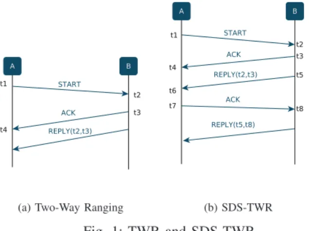
Ranging gives an estimate of the distance between two nodes. To compute the range between two nodes, protocols need to collect either the Time of Flight (ToF) or the Received Signal Strength (RSS) from source to destination. ToF-based protocols compute the distance by multiplying the ToF by the propagation speed. In Time of Arrival (ToA), a mobile sends a message to an anchor marking the emission time. Once received, the anchor records the reception time and sends this information back to the mobile node in order to estimate the ToF by subtracting both timestamps. This simple approach requires, however, a common notion of time between nodes. In other words, a synchronisation between node’s clocks is mandatory. The conventional two-way ranging protocol (TWR) estimates the range without a common timing reference. In this protocol (Figure 1a), the mobile node sends
a START message recording the departure time t1. Once this
message is received by an anchor, the anchor records the
arrival time t2and sends the corresponding acknowledgement
(ACK) back to the mobile, recording also the departure time
t3. After receiving the ACK message, the mobile node will
also record the arrival time t4. Since it is usually impossible
embed this information in the ACK response), a second REPLY message is sent back to the mobile node carrying the
information regarding t2 and t3. With this information at the
mobile node side, the ToF can be computed as follows:
T oF = t4− t1− (t3− t2)
2 (1)
An improvement of TWR, named 2M-TWR, was proposed
(a) Two-Way Ranging (b) SDS-TWR
Fig. 1: TWR and SDS-TWR
in [10]. In this work, authors make use of an advanced functionality of the DecaWave DW1000 [2] transceiver that allows sending a frame at a precise time. Thanks to this feature, the MAC-layer has the ability to generate a frame
which includes its future transmission time. Then, both t2and
t3 can be embedded in the ACK response, reducing then the
number of message exchanges since the REPLY message is no longer needed.
One of the sources of error in TWR protocol is the clock skew. Crystal oscillators used in sensor nodes do not work exactly at the nominal frequency, so there may be a small positive or negative offset in the time measurements. Since propagation speed is almost the speed of light, even a small offset causes a significant error in ranging. The Symmetric Double-Sided Two Way Ranging (SDS-TWR) shown in Figure (1b) was proposed to reduce the clock skew error. By means of two TWR’s, it reduces the impact of clock skew on the ranging results. The ToF can then be computed as:
T oF =t4− t1− (t3− t2) + (t8− t5) − (t7− t6)
4 (2)
Unlike the TWR algorithm, SDS-TWR algorithm needs at least 4 packets to get ranging information. Moreover, in order to eliminate the effects of clock skews, it assumes that the reply time at the sender A is the same as the reply time of receiver B. Different variants of SDS-TWR have been proposed in literature. In [8], authors propose the SDS-TWR-Multiple Acknowledgement (SDS-TWR-MA) in which the an-chor sends multiple ACK frames for a single START message from the mobile node. The basic idea behind the proposed algorithm is to use multiple acknowledgement (ACK+REQ) packets to a single ranging request, instead of iterating the whole ranging process to get a stabler ranging result. Accord-ing to their results, the rangAccord-ing algorithm reduces the number
of ranging packets 33% compared to TWR. Unlike SDS-TWR-MA, the scheme proposed in this paper keeps the number of frame exchanged identical to a basic TWR. Our aim is to improve the accuracy of TWR by making use of the information obtained from previous ranging exchanges. In [9], authors propose Double Two-Way Ranging (D-TWR) protocol for estimating the ToF, reducing the effects of clock skews without the assumption of identical reply time between nodes A and B. Node A starts the ranging by sending a START
message and, after a fixed delay τA, a second message is sent
to node B. By using a fixed time delay, the reply time of each device is no longer needed. Results show that D-TWR can reduce the number of ranging packets when compared to SDS-TWR. Even though SDS-TWR helps in reducing the impact of skew, it has the drawback that the number of exchanged messages is incremented, an issue that may be prohibitive for certain applications. The goal of all previously presented works is to present a ranging protocol that provides the most accurate instantaneous ranging measurement. Hence, protocols that perform better are normally those increasing the number of frames. In this work, and contrarily to this, we aim to keep the number of exchanged frames at minimum and constant. This objective has several advantages : (i) ranging exchanges reduce the bandwidth of other communication and hence, minimising these exchanges offers more bandwidth to other network services. (ii) we investigate ranging for UWB sensors where energy expenditure has to be kept at minimum. Our scheme offers a reduced energy expenditure compared to others. To improve the ranging with a scheme as simple as TWR, our idea is to leverage the ranging exchanges of the past. Indeed, several applications necessitate regular ranging of mobile devices for localisation purposes. Each time the rang-ing is performed, useful information regardrang-ing local clocks is exchanged between nodes. Provided that such exchanges exist, we show in this paper that it is possible to drastically improve the ranging accuracy of TWR by learning the clock skew between the nodes. This clock skew is considered in the ToF computation to adjust both clocks to the same rate. Our approach, called Skew-Aware TWR, is compared by extensive measurements to SDS-TWR. It is shown to be as precise as SDS-TWR while reducing the number of exchanged messages (two frames less than SDS-TWR).
III. BACKGROUND
The IEEE 802.15.4a is the first international standard that provides a specific physical layer capable of wireless ranging. Two formats of communication signal are proposed: Impulse Radio Ultra-Wide Band (IR-UWB) signals and the chirp spread spectrum (CSS) signals, both of them suitable for data communication as well as for ranging purposes. In this work, we consider the IR signal format. The packet format proposed by the standard is shown on Figure 2. The network preamble is used to synchronise entities and informs of the arrival of a packet. The preamble length is one of 16, 64, 1024 or 4096 symbols and is chosen depending on the required performance in terms of the positioning precision. For example, a larger preamble size helps low quality receivers to gain higher SNRs
Fig. 2: IEEE 802.15.4a packet
while a smaller preamble size reduces the channel occupancy and leads to reduced energy consumption. The SFD is a short sequence of 8 or 64 symbols indicating the end of the preamble and the start of the physical layer header. It is used to establish frame timing and its detection is important for accurate estimation. According to the standard, a device may implement the optional ranging support by specifying a RFRAME frame. The RFRAME is indicated by setting a ranging bit in the PHY header of the packet. The range between two nodes (devices) is determined typically via two-way time of arrival (TWR-ToA) of a RFRAME by recording its arrival time. However, TWR-ToA requires a common timebase between both nodes. A slightly modified version of the TWR-ToA protocol is proposed by the standard which do not require a common timing reference (Figure 1a). Two counter values are necessary to report: the ranging counter start value, which
represents the time of arrival (ToA)(t2) of the first pulse of
the first symbol of the PHR, also known as RMARKER, and the ranging counter stop value representing the time when
the RMARKER of the ACK packet leaves the antenna (t3).
Then, the timestamp report should contain both(t2) and (t3).
This timestamping requires a very high precision timer, with a typical precision of 100ps.
IV. ACCURATEAPPROACH FORTOFESTIMATION
As explained before, SDS-TWR protocol improves TWR as it reduces the impact of the clock skew on the rang-ing estimation. However, the improvement in terms of ToF estimation is achieved to the detriment of the number of exchanged messages, which is increased compared to TWR. From Figures (1a) and (1b), we can see that, while only three messages are necessary for TWR to compute the ToF, a total of five messages are required for SDS-TWR. This issue may be prohibitive, specially for applications requiring minimal power consumption. In this section, we introduce a new approach for estimating the ToF in UWB by compensating the skew between node’s clock and minimising the number of exchanged messages.
A. Skew-Aware TWR Approach
The proposed approach is based on TWR. As shown in Figure (1a), once the reply message reaches the destination, node A will be able to estimate the ToF as in equation (1).
However, t4− t1 and t3− t2 are values that are computed
by different nodes having different clock frequencies. Hence,
the real elapsed time t3− t2 from node A standpoint will
differ from the elapsed time experimented at node B. Authors in [4] propose a skew compensation based on a DecaWave DW1000 functionality that offers an estimate of the frequency
relationship between nodes A and B: k = fB
fA. From k, the
estimation of the ToF can be computed as follows:
T oF′= t4− t1− k(t3− t2)
2 (3)
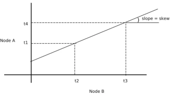
This approach is platform-dependent in the sense that it depends on the DecaWave DW1000 functionality. In order to be able to estimate the skew, we propose an approach based on linear regression that allows us to estimate this value for any type of platform. To find the linear regression solution, an approach based on least squares methodology [11] provided by the SciPy scientific library [7] for Python, is used. From the message exchanges shown in Figure (1a), node A will receive
t2and t3representing the dates when the first pulse of the first
symbol of the PHR of the START message arrives to node B and the moment when the SFD marker of the ACK packet leaves the antenna, respectively. This information would be useful to node A for estimating the skew of node B with respect to node A. This can be done as shown in Figure 3 where the line’s slope represents the skew between node A and B. This first TWR iteration will allow node A to obtain
Fig. 3: Skew estimation
a first rough estimate of the skew between itself and node B,
based on the line passing through points (t2, t1) and (t3, t4).
Successive message exchanges will allow node A to estimate a more accurate skew by means of a linear regression approach
which will consider, not only the current points (t2, t1) and
(t3, t4), but also those previously computed. By successively
computing the slope of the regression line, the estimation of the ToF can be improved in the same way as done in [4] but considering the line’s slope in this case:
T oF′′= t4− t1− slope(t3− t2)
2 (4)
An important point to emphasise is the fact that our linear regression approach approximates the skew by assuming the
global instants t1and t3to be equal to t2and t4, respectively.
In other words, the propagation time is neglected. This as-sumption is not unreasonable given that the propagation time is around 9 nanoseconds (for a distance of 2 meters) while
(t4− t1) and (t3− t2) are around 300 microseconds. Clearly,
the impact of these few nanoseconds over the skew can be considered as negligible. Another important point is regarding
the channel access mechanism. In our approach, every time a node has a message to send (START, ACK, REPLY), it sends it in an Aloha fashion. In other words, we do not do an access control when sending UWB frames. By means of this scheme, we avoid delaying the reception of timestamps (which may have a non-negligible impact in the ToF and thus, in the ranging estimation). In next Section, we present the results of this improvement with respect to the estimated ToF for both skew and no-skew-aware approaches. We also present a comparison between our Skew-Aware TWR approach and SDS-TWR. Considering the fact that SDS-TWR-MA is more efficient and accurate than SDS-TWR, the best would be to compare our approach with SDS-TWR-MA. However, and since we do not have an implementation of this protocol in our testbed, comparisons were done between our approach and SDS-TWR protocol (available in our testbed platform).
V. EXPERIMENTS& RESULTS
In this Section, we present the experimental results we have obtained regarding the estimation of the skew-compensated ToF. Experimentations were ran in our open framework
DecaDuino [10] by using the UWB physical layer of De-caWave [2]. After a description of our testbed, we present preliminary results concerning the impact of the antenna in the estimation of the ToF. These results were useful for us to better configure test scenarios. Next, we present a comparison in terms of the distance error of the traditional TWR (without skew) and the one proposed in this work. We also compare the skew estimation of our approach with a DecaWave function-ality allowing to compute this value. Finally, and considering the fact that the SDS-TWR was conceived for estimating the ToF by minimising clock skew, a comparison of our approach with SDS-TWR is presented.
A. Testbed Description
DecaDuino [10] is a Physical-layer Service Access Point (PHY-SAP). It provides the two conventional Physical-Data (PD) and Physical Layer Management Entity (PLME) SAPs which enable MAC-level protocols to send/receive data and configure the transceiver (channel, transmission rate, preamble parameters...). Since this framework was designed to aid in the implementation of ToF based protocols, DecaDuino also provides access to the Physical-level 64GHz high precision timer which enables precise message timestamping at both
transmission (tT X) and reception (tRX). Finally, DecaDuino
implements advanced synchronization/timestamping function-alities such as delayed transmission and receiver skew evalua-tion. A compliant hardware called DecaWiNo is also described in [10]. On this design, the transceiver is a DWM1000 and the Arduino board is a Teensy 3.2 which embeds an ARM Cortex M4 32-bit MCU rated at 72MHz, with 64kB RAM and 256kB program memory. In order to minimise the impact of reflections, some of the experiments were carried out in an anechoic chamber (6 meters x 4 meters x 2.5 meters).
B. Preliminary Experimentations & Results
The idea behind these series of experiments was to be able to determine the impact of the antenna’s position over the ToF.
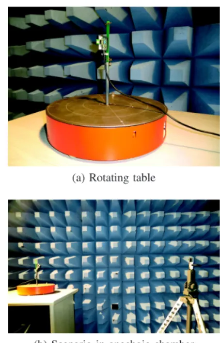
Therefore, we have carried out experiments by using a rotating table (Figure 4a) and taking ToF measurements as the table turns. The two nodes were separated by a distance of 2 meters. Experimentation was carried out in an anechoic chamber (Figure 4b) in order to minimise the impact of reflections. Figure 5 shows the configuration of the first scenario. Details for each of them are shown in Table I. During the execution,
node B is fixed while node A, starting at 0◦, turns 5◦ per
second until reaching an angle of 180◦. ToF is then measured
for different angles of incidence of node A’s antenna based on the TWR protocol (without skew). Figure 6 shows, for each scenario, the results in terms of the distance error for different angles of incidence. From them, we can see the importance of the antenna’s alignment with respect to the quality of ToF measurements and therefore, in the distance error. In fact, for each of the scenarios we can see that, as node A’s antenna get
closer to 90◦, the distance error is reduced, independently of
node B’s configuration. Table II summarises the experiment. For each of the scenarios we show the average distance error and the standard deviation, together with the points (angles) where we achieve the best and the worst values. From this we can see that both scenarios 2 and 3 seem to be better than the others. A minimal error is achieved when the antenna’s
angle for node A is around 75◦ for both nodes in vertical
position (or vertical and horizontal position for node A and B, respectively). These results were useful for us to find an optimal configuration for estimating and comparing the ToF in different scenarios (no-skew, skew based on linear regression, skew DecaWave), as we will see next.
(a) Rotating table
(b) Scenario in anechoic chamber
Fig. 4: Rotating table & anechoic chamber.
C. TWR and Skew-Aware TWR Comparison
In this experiment, our objective is to measure the accuracy improvement of our Skew-Aware TWR approach compared to legacy TWR. In order to carry out this, we have set up four different test scenarios where the distance between
Fig. 5: Scenario 1
Node A Node B
Scenario Position Angle’s rotation Position Fixed Angle Scenario 1 Vertical 0◦- 180◦ Vertical 0◦
Scenario 2 Vertical 0◦- 180◦ Vertical 90◦
Scenario 3 Vertical 0◦- 180◦ Horizontal 90◦
Scenario 4 Horizontal 0◦- 180◦ Horizontal 90◦
TABLE I: Scenario’s configuration.
Scenario Mean(cm) St.Dev(cm) Max Min
Angle◦ Error(cm) Angle◦ Error(cm)
Scenario 1 81 6.1 0 92 75 68
Scenario 2 53 7.4 0 61 75 27
Scenario 3 42 7.1 0 56 70 28
Scenario 4 58 4.7 0 68 55 47
TABLE II: Distance error vs angle of incidence (antenna)
0 45 90 135 180 Angle (Degree) 10.00 19.89 29.78 39.67 49.56 59.44 69.33 79.22 89.11 99.00 Err or (centimeters)
Distance Error (in centimeters)
Scenario 1 Scenario 2 Scenario 3 Scenario 4 Fig. 6: Distance error vs angle of incidence (antenna)
nodes is varied. The comparison is done in terms of the distance error computed from the estimated ToF for: traditional TWR (without skew compensation), Skew-Aware TWR (skew estimated from a linear regression approach) and also Skew-Aware TWR where the skew is estimated from the DecaWave’s functionality.
1) Scenarios: Scenarios were set up in two different envi-ronments: an anechoic chamber as well as in a non-isolated room. Table III shows all tested configurations. Based on the preliminary results presented in section V-B, antennas were
aligned in an optimal way (angle of 75◦ for node A and 90◦
for node B). For practical reasons, we consider the second scenario’s configuration where both nodes are in vertical position. The idea then is to compute the ToF estimated from
Scenario Room Distance (meters)
Scenario 5 Anechoic Chamber 2 Scenario 6 Anechoic Chamber 3 Scenario 7 Non-isolated Room 1 Scenario 8 Non-isolated Room 2 Scenario 9 Non-isolated Room 3
TABLE III: Scenario’s configuration for ToF measurements
the original TWR and the Skew-Aware TWR (by means of both skew approaches). Then, based on the measured ToF, the distance error is found. An acceptable distance error in absolute terms is about 5, 15 and 30 centimetres for a distance between A and B of 1, 2 and 3 meters, respectively. We considered two methods for estimating the skew: a linear regression approach presented in IV-A and the DecaWave’s functionality. We also present a comparison between both of them.
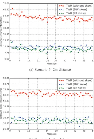
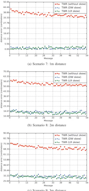
2) Results: Figure 7 and 8 present the results in terms of the distance error computed from the ToF estimation for each of the predefined scenarios. The first conclusion we can draw from these results is that the estimation of the ToF is significantly improved when compensating it with the skew estimation. This result was also confirmed in [4] for a skew estimated by means of the DecaWave’s functionality. Secondly, we can see that there is no significant difference between the estimation done by both skew compensation techniques. This is due to the fact that both skew estimations are not so far from each other. Figure 9 shows the skew’s evolution in parts per million (ppm) for both approaches. Green line represents the evolution of the computed slope while red points represent the estimated skew from DecaWave DW1000 transceiver. Table IV presents the average distance error for scenarios 5, 6, 8 and 9. The last two columns show that the distance error is almost the same for both skew estimation approaches. However, a slight improvement in the ToF estimation can be achieved when compensating the skew by linear regression (LR).
0 7 14 21 28 34 41 48 55 62 Message 0.00 7.78 15.56 23.33 31.11 38.89 46.67 54.44 62.22 70.00 distance er ror (centimeters) TWR (without skew) TWR (DW skew) TWR (LR skew)
(a) Scenario 5: 2m distance
0 6 12 18 24 30 36 42 48 54 Message 25.00 32.22 39.44 46.67 53.89 61.11 68.33 75.56 82.78 90.00 distance er ror (centimeters) TWR (without skew) TWR (DW skew) TWR (LR skew) (b) Scenario 6: 3m distance
0 7 13 20 26 33 39 46 52 59 Message 0.00 5.56 11.11 16.67 22.22 27.78 33.33 38.89 44.44 50.00 distance er ror (centimeters) TWR (without skew) TWR (DW skew) TWR (LR skew)
(a) Scenario 7: 1m distance
0 7 13 20 26 33 39 46 52 59 Message 10.00 16.67 23.33 30.00 36.67 43.33 50.00 56.67 63.33 70.00 distance er ror (centimeters) TWR (without skew) TWR (DW skew) TWR (LR skew) (b) Scenario 8: 2m distance 0 7 13 20 26 33 39 46 52 59 Message 25.00 32.22 39.44 46.67 53.89 61.11 68.33 75.56 82.78 90.00 distance er ror (centimeters) TWR (without skew) TWR (DW skew) TWR (LR skew) (c) Scenario 9: 3m distance
Fig. 8: Distance error comparison: non-isolated room Average Error (meters)
Scenario without skew skew(LR) skew(DW)
Scenario 5 (ACH) 0.519 0.120 0.146 Scenario 6 (ACH) 0.70 0.357 0.372 Scenario 8 (NIR) 0.534 0.145 0.158 Scenario 9 (NIR) 0.70 0.306 0.316
TABLE IV: Average error comparison between TWR (without skew), TWR (skew Linear Regression (LR)) and TWR (skew DecaWave (DW))
D. SDS-TWR and Skew-Aware TWR comparison
Since SDS-TWR has been designed to minimise the impact of the clock skew, our objective in this experiment set-up is to compare SDS-TWR with the Skew-Aware TWR in terms of the distance error. Based on results presented in previous section (Figure 9), we only consider the skew compensation based on linear regression since it is more accurate than the
0 10 20 30 40 50 Message −13.00 −11.75 −10.50 −9.25 −8.00 Sk ew (PPM) Skew Evolution (DW) Slope Evolution (LR)
Fig. 9: DecaWave (DW) and Linear Regression (LR) skew evolution in parts per millon (ppm)
DecaWave’s functionality.
1) Scenarios: Two scenarios were considered for this ex-periment, both of them were ran in a non-isolated room for two distances: 2 and 3 meters. Detailed results are given in Table V.
Scenario Room Distance (meters)
Scenario 10 Non-isolated room 2 Scenario 11 Non-isolated room 3
TABLE V: Scenario’s configuration for SDS-TWR and TWR comparison
E. Results
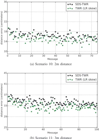
Figure 10 shows the results in terms of the distance error between SDS-TWR and our TWR approach with skew com-pensation. SDS-TWR was conceived to estimate the ToF by taking into account the effect of clock skew in nodes. However, this improvement in the ToF (and therefore in the distance error), is reached to the detriment of the number of messages exchanges between nodes, which increase in order to be able to get ranging information from the other node. As seen in Figure (1b), a total of five packets are needed to compute the ToF. We can see from Figure 10 that for both scenarios, the distance error estimated by our approach is better than the one from the SDS-TWR. Table VI shows the average distance error for both protocols. While SDS-TWR needs at least five messages to achieve this precision, our approach requires only three messages. Moreover, this number can be reduced to two messages if we consider the protocol 2M-TWR allowing to
embed t2 and t3 in the ACK message, as done in [10].
Average Error (meters) Scenario SDS-TWR TWR (LR skew) Scenario 10 0.164 0.150 Scenario 11 0.343 0.328
TABLE VI: Distance error between SDS-TWR and TWR (with skew compensation).
F. Discussion
In section V-C, we have evaluated our Skew-Aware TWR with the traditional TWR protocol. From the results we can
0 10 20 30 40 50 60 70 Message 10 14 18 22 26 30 distance er ror (centimeters) SDS-TWR TWR (LR skew)
(a) Scenario 10: 2m distance
0 20 40 60 80 100 Message 25 29 33 37 41 45 distance er ror (centimeters) SDS-TWR TWR (LR skew) (b) Scenario 11: 3m distance
Fig. 10: SDS-TWR vs TWR with skew comparison
conclude that our approach for compensating the clock’s skew improves the performance of the ToF estimation without new message addition. This is an important improvement to the TWR protocol for accurately estimating the ToF, and consequently, the ranging between nodes. In order to estimate the skew, two approaches were proposed: the first based on a linear regression estimation and the second one considering the functionality of DecaWave. Both approaches improve the performance of the ToF estimation, as shown in Figures 7 and 8. However, results from the linear regression are slightly better than the those estimated by the DecaWave’s functionality. Besides, the linear regression approach can be applied independently of the underlying hardware. We have also compared our Skew-Aware TWR approach with SDS-TWR in terms of the distance error. Results in section V-D show that our approach is slightly better than the estimation provided by SDS-TWR. However, SDS-TWR requires at least five message exchanges for getting ranging informations while Skew-Aware TWR keeps the same number of messages as the traditional TWR.
VI. CONCLUSIONS ANDFUTURE WORK
In this paper, we have presented an approach that accurately estimates the ToF. The well-known pitfall of TWR is that it doesn’t compensate the clock’s skew during ranging, result-ing in a coarse estimate of inter-node distance. SDS-TWR overcomes this problem by reducing the effect of clock skews
to the detriment of the number of message exchanges. Our Skew-Aware TWR is based on TWR protocol and proposes a way to compensate clock’s skews by means of a linear regression approach. Results show that our approach is suitable for reducing the distance error between nodes, when distance is computed from the estimated ToF. Results also shown that a better performance is obtained by means of our approach when compared to SDS-TWR in terms of distance error and number of messages exchanged. The linear regression analysis allows us to validate the DecaWave functionality with respect to the skew estimation. In future works, we will more extensively measure the impact of mobility of nodes on our ranging approach. We therefore plan to investigate the derivation of our linear regression for a finite size temporal window. Moreover, we plan to compare our Skew-Aware TWR to the most accurate SDS-TWR-MA solution, in terms of precision and energy consumption.
REFERENCES
[1] T.A. Alhmiedat and S.H. Yang. A zigbee-based mobile tracking system through wireless sensor. 2008.
[2] Bradford Campbell, Prabal Dutta, Benjamin Kempke, Ye-Sheng Kuo, and Pat Pannuto. Decawave: Exploring state of the art commercial localization. April 2015.
[3] K. Chen, N. Pissinou, and K. Makki. Cellular network location estimation via rss-based data clean enhanced scheme. In Computers
and Communications (ISCC), 2011 IEEE Symposium on, pages 924–
930, June 2011.
[4] Nezo Ibrahim Fofana, Adrien Van den Bossche, Rejane Dalce, and Thierry Val. An original correction method for indoor ultra wide band ranging-based localisation system. http://arxiv.org/abs/1603.06736, 2015.
[5] IEEE Computer Society, LAN/MAN Standards Committee, Institute of Electrical and Electronics Engineers, and IEEE-SA Standards Board.
Specific requirements Part15.4: Wireless Medium Access Control and Physical Layer Specifications for Low-Rate Wireless Personal Area
Net-works. Amendment 1. Institute of Electrical and Electronics Engineers,
New York, NY, 2007.
[6] Gints Jekabsons, Vadim Kairish, and Vadim Zuravlyov. An Analysis of Wi-Fi Based Indoor Positioning Accuracy. Scientific Journal of Riga
Technical University. Computer Sciences, 44(1), January 2011.
[7] Eric Jones, Travis Oliphant, Pearu Peterson, et al. SciPy: Open source scientific tools for Python.
[8] Hakyong Kim. Performance analysis of the sds-twr-ma algorithm. In
Proceedings of the 2009 International Conference on Wireless
Com-munications and Mobile Computing: Connecting the World Wirelessly,
IWCMC ’09, pages 399–403, New York, NY, USA, 2009. ACM. [9] Myungkyun Kwak and Jongwha Chong. A new double two-way ranging
algorithm for ranging system. In Network Infrastructure and Digital
Content, 2010 2nd IEEE International Conference on, pages 470–473.
IEEE, 2010.
[10] Adrien Van den Bossche, Rejane Dalce, Nezo Ibrahim Fofana, and Thierry Val. Decaduino: An open framework for wireless time-of-flight ranging systems (regular paper). In IFIP Wireless Days
(WD), Toulouse, 23/03/2016-25/03/2016, page (electronic medium),
http://ieeexplore.ieee.org/, mars 2016. IEEExplore digital library. [11] Xin Yan and Xiao Gang Su. Linear Regression Analysis: Theory and
Computing. World Scientific Publishing Co., Inc., River Edge, NJ, USA,