OATAO is an open access repository that collects the work of Toulouse
researchers and makes it freely available over the web where possible
Any correspondence concerning this service should be sent
to the repository administrator:
[email protected]
This is an author’s version published in:
http://oatao.univ-toulouse.fr/24506
To cite this version:
Falcade, Tiago and Turq, Viviane
and Bonino, Jean-Pierre
and Fraga
Malfatti, Célia de
Tribological properties of amorphous carbon films
obtained by electrodeposition from DMF using 2HEAL protic ionic liquid as
dopant. (2017) Diamond and Related Materials, 71. 30-37. ISSN 0925-9635
Tribological properties of amorphous carbon
films obtained by
electrodeposition from DMF using 2HEAL protic ionic liquid as dopant
Tiago Falcade
a,⁎
, Viviane Turq
b, Jean-Pierre Bonino
b, Celia de Fraga Malfatti
ba
Federal University of Rio Grande do Sul, Brazil
bUniversité Toulouse III – Paul Sabatier, France
a b s t r a c t
a r t i c l e i n f o
Amorphous carbonfilms are widely used for improving the surface mechanical properties of metallic materials, substantially increasing the wear resistance [1,2]. Traditionally this type offilm is obtained by vapor phase methods, which, in spite of being in a high technical and scientific development level have been associated with a number of limitations, in particular with regards to the implementation cost and largefilm production. In this context, electrodeposition shows itself as an alternative to traditional methods: it has low cost and limits the use of complex techniques, which generally require high temperatures and vacuum and cannot be applied for coating on substrate with complex shapes and large dimensions. It is true that the electrodeposition of carbon films also has experimental limitations, such as the limited deposition rate and, therefore, the aim of this work is to investigate the influence of the ionic liquid 2 HydroxyEthylAmine Lactate (2HEAL) in obtaining amorphous carbonfilms. An improvement in deposition rate by increasing electrolyte conductivity with the addition of ionic liquid is expected. This work is meant to investigate the changes occurring in thefilms with the addition of ionic liquid, especially from the standpoint of surface mechanical properties such as tribological behavior and interfa cial properties. The results show that the addition of the ionic liquid led to change in the structure of thefilm, resulting in an improvement in the mechanical properties, as observed by reduced friction coefficient. An in crease of abraded area of counterface and an increase of elastic work also indicates that behavior.
Novelty statement: The aim of this study was to obtain carbon films by electrodeposition using 2 HydroxyEthylAmine Lactate doped N,N DiMethylFormamide as electrolyte, in order to increase deposition rate. It will be thefirst report about the use of ionic liquids as dopants in the electrodeposition of carbon films. In addition, mechanical properties of the obtainedfilms were evaluated and their relationship with the amounts of dopant was explored.
Keywords: Carbonfilm Ionic liquid DMF Electrodeposition 1. Introduction
Carbonfilms present excellent tribological properties and they can be used as coatings of metallic materials in various applications, espe cially in order to increase wear resistance[1 5]. For this purpose, carbon coatings show up as an interesting alternative coating of titanium alloys for biomedical[6 9]and aerospace applications[10,11]. Traditionally this type of coating is obtained by physical or chemical vapor deposition [12 15]. However, these techniques are expensive and require complex experimental apparatus. In this way, to obtain carbonfilms directly on
the surface of titanium alloys, in an efficiently and economically viable manner becomes a challenge.
In this context, the electrodeposition shows enormous potential, especially for not requiring vacuum systems and high temperature [16,17]. In addition, this technique allows coating components of complex geometry and it has several operating parameters that allow controlling the properties of thefilms. Typically, the electrodeposition of carbon films uses organic solvents as electrolyte, and N,N DiMethylFormamide (DMF) and ACetoNitrile (ACN) are among the most widely explored in the literature[17,18]. However, the deposition with these solvents leads to experimental limitations, in particular with respect to deposition time and to voltage required for polarization, acti vation and reaction of organic molecules[17].
Some work has been reported on the use of dopants in deposition solutions, in order to increase the conductivity of the electrolyte. These dopants are mostly aqueous solutions containing possibly some kind of salt[19,20]. The problem of this dopant type is inevitable
⁎ Corresponding author at: Laboratory of Physical Metallurgy - LAMEF; Program of Postgraduate Studies in Mining, Metals and Materials Engineering - PPGE3M; Institute of Chemistry; Federal University of Rio Grande do Sul, UFRGS 9500 Bento Gonçalves Ave. UNIDADE EMBRAPII 91501-970, Porto Alegre, RS, Brazil.
E-mail addresses: [email protected] (T. Falcade), [email protected]
(V. Turq), [email protected] (J.-P. Bonino), [email protected] (C. de Fraga Malfatti).
occurrence of parallel reactions during the deposition and the compati bility with the original organic solution.
Aiming to improve the characteristics of the electrolyte leading to an increase in the deposition rate of thefilms, this research proposes the use of ionic liquids as dopants, operating as supporting electrolyte and consequently increasing the conductivity of the deposition solution [21,22], favoring polarization of organic molecules. After the deposition, the differentfilms obtained were compared regarding their morpholog ical, structural, tribological and mechanical properties, checking the ef fect of doping on their characteristics.
2. Materials and methods
The substrate used in this work was a titanium alloy, Ti6Al4V disks that were mechanical polished using #600 #4000 SiC sandpaper and subsequently polished with 1μm size diamond paste. The samples were cleaned with distilled water and ethanol.
Electrodeposition technique was used for the deposition of carbon films. The cell was a traditional two electrodes: a working and a counter electrode. The working electrode was the substrate sample itself, in a Teflon holder, with a constant exposed area of 0.31 cm2
, and the counter electrode was a graphite plate, 10 mm distant from the working elec trode. Temperature was kept constant at 20 °C using a thermostatic bath. For the deposition, an electric voltage of 1200 V was applied be tween the electrodes using a high voltage source, many authors report ed this magnitude of voltage in order to obtain carbonfilms with amorphous characteristics[18,23 25]. In all systems, the deposition time was 24 h.
One of the most important parameters in the electrodeposition pro cess is the electrolyte composition. In this work N N; DiMethylFormamide (DMF) (FMaia 99%) was tested as electrolytes, as well as mixtures of DMF and 2 HydroxyEthylAmine Lactate (2HEAL), used as dopant, in order to increase the electrolyte conductivity, it is common to use ionic liquids as support electrolyte in electrodeposition process[26 29]. Normally, aprotic ionic liquids are used in this way, however this kind of ionic liquid have high cost and low stability, for this reason in this work a protic ionic liquid is used. The main difference of protic ionic liquids compared to the traditional aprotic is the presence of at least a proton, which is/are able to promote extensive hydrogen bonding[30]. In addition this family of ionic liquids are interesting alter native due their low cost and simple synthesis rout[31]. Three concen trations of this ionic liquid in the electrolyte were tested: 0.03 vol% (DMF30LI), 0.05 vol% (DMF50LI) and 0.1 vol% (DMF100LI).
Morphology of the samples before and after the deposition of the films was observed by atomic force microscopy (Shimadzu contact mode, size 2μm × 2 μm), scanning electron microscopy (Jeol, 6060, 20 kV, Secondary Electron and Backscattered Electron Imaging mode) and optical microscopy (Keyence 3D optical microscope). The local roughness was measured using the profiles of AFM. Raman spectrosco py (Renishaw; laser 514 nm, 5 accumulations, exposure time 20 s 120 s) was used in order to analyze the type and amount of carbon bonds in the structure of thefilm, this procedure allows evaluating the type of amorphous carbonfilm obtained. The reference used for peak position was based on the studies of Beeman et al.[32], Dillon et al. [33]and Ferrari and Robertson[34].
Adhesion of thefilms was investigated by Scratch tests, with a Nano Scratch Tester (CSM Instruments) with spherical diamond indenter (di ameter of 5μm) applying a progressive loading from 3 to 500 mN. The facies and the optical critical loads of tracks were analyzed by optical microscopy, and the elastic recovery of the groove was evaluated by measuring the penetration depth during the scratch test and after the test. The mechanical properties (Young's modulus, surface hardness) were evaluated using nanoindentation test (UltraNanoIndenter, CSM Instruments) with a normal force of 10 mN, with a modified Berkovich indenter. The Oliver & Pharr analysis method [35] was used for calculation.
Friction tests were performed on a linear ball on plate tribometer (CSM Instruments). To evaluate the tribological behavior of thefilms, sliding was conducted with a reciprocal linear motion of an alumina ball (diameter of 6 mm). Constant normal force of 1 N, corresponding to an average Hertzian pressure of 400 MPa; sliding speed of 0.63 cm/ s and track length of 2 mm were used. The dimensions and facies of the tracks were evaluated by optical and electronic microscopy. 3. Results and discussion
The analysis of the substrate indicates that the mechanically polished surface is characterized by a uniform texturing which could favor the deposition, providing well distributed sites to anchor the
Fig. 1. AFM image of the polished substrate before deposition.
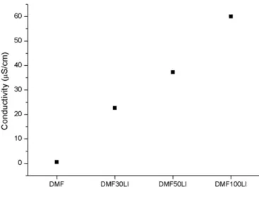
Fig. 2. Conductivity of the tested electrolytes.
Table 1
Layer thickness of thefilms obtained from organic liquids with and without dopant.
System Layer thickness (μm)
DMF 4.5 ± 0.2
DMF30LI 8.1 ± 0.4
DMF50LI 12.9 ± 1.8
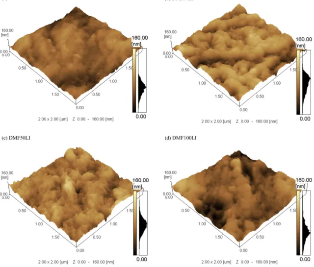
film, as shown in the AFM image (Fig. 1). The substrate presents very low local roughness as showed inFig. 4. However, after deposition there was a clear change in the appearance of the surface: globular for mations of thefilm onto the substrate lead to an increase in surface roughness (Fig. 3a). This fact is associated with a phenomenon of pref erential polarization, wherein the material is favorably deposited on the substrate inhomogeneities or defects, such as peaks or valleys on
the surface. As observed by Zhang[36]and Gupta[37,38], after the nu cleation phase, the carbon nuclei come into a growth phase, and began to thicken thefilm. As the deposition rate is low, the carbon globules formed were coarse.
The insertion of protic ionic liquid in DMF increases the conduc tivity of the solution as can be seen inFig. 2, thereby increasing the
Fig. 3. AFM image of thefilm surface obtained from: (a) DMF; (b) DMF30LI; (c) DMF50LI; (d) DMF100LI.
electrodeposition current density and consequently increasing the deposition rate (Table 1). AFM images of thefilms obtained from so lutions containing 0.03 vol%, 0.05 vol% and 0.10 vol% of ionic liquid Figs. 3b; c; and d, respectively show a globular structure with ag glomerates constituting thefilm. The same mechanism of nucleation and growth in thickness was observed. However, since the deposi tion rate is higher for systems with dopant, a larger quantity of nuclei was formed, followed by growth in thickness. This effect, locally ob served by AFM, showed a structure withfiner agglomerates with in creasing amounts of dopant, leading to increased local roughness (Fig. 4), as observed by Zhang[36].
In addition, the presence of dopant caused a progressive increase in the thickness of thefilms measured from cross sections by scanning electron microscopy, as can be seen inTable 1. This increase is related to the higher conductivity of the electrolyte and the consequent in crease in current deposition, leading to a higher deposition rate. In fact, thefilms obtained without the dopant showed a deposition rate of 190 nm/h while the addition of 0.1 vol% of 2HEAL led to an increase to rates around 750 nm/h.
Regardless of presence or absence of ionic liquid in the deposition solution thefilms have typical characteristics of amorphous carbon films, as can be observed in the Raman spectra (Fig. 5). These spectra show the presence of G band associated with the presence of sp2type hybridizations and D band associated with the disorder of sp2bonds, this disorder may be associated with the presence of carbon atoms bonds with sp3type hybridizations.
The positions of D and G and the ID/IGratio can be correlated with the percentage of four fold coordinate bonds, characterizing the sp3type hybridizations[32]and the number and/or size of graphite crystallites [33]. The ID/IGintensity ratio was calculated and the values were around 0.73 for DMF and between 0.67 and 0.72 for the systems that uses ionic liquids as dopants in the deposition solution. The crystallite size could be calculated through the linear model proposed by Dillon et al.[33], leading to typical crystallite size of 25 nm. These values are consistent with those proposed in the literature, both forfilms obtained by electro deposition, as those obtained by vapor phase techniques. As reported by Dines[39], a C carbonfilms obtained by PVD can present ID/IGranging between 0.82 and 1.62. Carbonfilms obtained by electrodeposition
using organic liquid and organic liquids in aqueous solutions showed ID/IGbetween 0.4 and 1.4[38,40 42].
The analysis of D and G bands enables interpreting the influence of the ionic liquid in amount of sp3hybridizations and graphite crys tallites[34,43]. All thefilms presented a graphitic character with presence of graphitic clusters.Fig. 5andTable 2show the depen dence of ionic liquids content in the position and intensity of D and G bands. The position of D band shifted slightly down with in creased amount of dopant, while the ID/IG ratio shifted slightly upwards, which could indicate a greater amount of sp3hybridiza tions and a reduction in number and/or size of graphite crystallites when the amount of ionic liquid increases. However, the most no ticeable effect is the downward displacement of the G band with the amount of dopant, possibly indicating a reduction in the amount of sp2hybridizations.
Changes in the structure of the carbonfilms influenced their physi cochemical characteristics and therefore their properties. From the viewpoint of surface mechanics, scratch tests showed that thefilms ob tained from DMF showed no delamination of the coating, only lateral material displacement was observed, with lateral pile up formation, which indicates good adhesion between thefilm and the substrate, as can be seen in the images of scratch tracks inFig. 6but plastic character. Plastic deformation indeed occurs at the beginning of the test, indicating that the minimum load is sufficient to permanently deform the films. The addition of ionic liquid to deposition solution did not affect signifi cantly the interfacial properties of carbonfilms, in the same way as for systems without dopant are observed scratch tracks with plastic defor mation since the beginning of load application, but induce a shift in the critical load value for lateral pile up formation
Lateral pile up formation begins for slightly higher loads for the systems with addition of ionic liquids (Table 3). In the case of pure DMF, the critical load to lateral displacement was 11 mN and after addition of dopant, critical loads ranged from 35 mN to 40 mN. There appears to be no significant influence of the amount of ionic liquid to the critical load of material displacement because even low dopant concentrations have increased their value, and the addi tion of a greater amount does only result in a slight increase in re sistance to displacement. This increased resistance to lateral pile
Table 2
Positions of the D and G bands and intensity ID/IGratio for thefilms.
System D center (cm 1) G center (cm 1) I D/IG
DMF 1341 ± 0.58 1591 ± 0.6 0.73 ± 0.006 DMF30LI 1341 ± 0.60 1585 ± 2.5 0.67 ± 0.010 DMF50LI 1340 ± 1.53 1586 ± 0.6 0.69 ± 0.015 DMF100LI 1336 ± 1.15 1579 ± 1.5 0.72 ± 0.021
Fig. 6. Scratch tracks of thefilms obtained from: (a) DMF; (b) DMF30LI; (c) DMF50LI; (d) DMF100LI. Table 3
Interfacial properties of thefilms obtained from different solutions.
System Welast/Wtotal Critical load to lateral pile-up formation [mN]
DMF 68% 11
DMF30LI 76% 35
DMF50LI 77% 35
up plastic formation can be related to the increase of the elastic nature of thefilms obtained with the addition of dopant, as evi denced by an increase in elastic work ratio during scratch test shown inTable 3.
Nanoindentation tests performed on the top surface of the studied films result in dispersed values of surface hardness. Probably this is re lated to the lack of surface homogeneity of thefilms in relation to the low load applied during the tests. Nevertheless, the substrate presents hardness reliable with titanium alloys, around 4400 MPa[44,45]. Among the films all had the same hardness range of between 3000 MPa and 3500 MPa (Fig. 7). These values are relatively smaller than those traditionally found by carbonfilms with high amount of sp3hybridizations, between 10 GPa and 30 GPa[43,46 49], however, were consistent with those observed by Thejaswini et al. in the case of sp2richfilms[50].
Young modulus of uncoated substrate (125 GPa) andfilms obtained with and without addition of ionic liquid are shown inFig. 7. Substrate presents values befitting to the literature[44,45,51]. In the case of car bonfilms, a reduction in elastic modulus with increasing the amount of ionic liquid was observed; this is in good agreement with the increase of the elastic nature of thefilms as evidenced by scratch tests (Fig. 7). Chung et al.[52]studied the deposition of amorphous carbonfilms onto Si by Plasma Assisted CVD (PACVD) and proposed a direct relation ship between the reduction of elastic modulus to the shift in G band to
lower wavelengths, the same behavior was observed with the addition of ionic liquid. Furthermore Jardret et al. have shown that the propor tion of plastic deformation during scratch test increases with the E/H ratio[53]. This could explain the increase of the elastic deformation ratio with the dopant addition.
Observing comparatively the coefficient of friction (COF) curves for all systems studied (Fig. 8) is quite clear the influence of the type of elec trolyte in the mechanical characteristics of the surface of the coated systems.
The coefficient of friction of the uncoated substrate showed an initial period in which polished substrate sliding against the alumina ball, followed by a period where COF oscillates around a mean value. This is due to the presence of a large number of particles (third body) arising from the worn substrate in the contact with the counterface [54]. When these particles were removed from the interface during the test, there was a reduction in the coefficient of friction which in creased again when new particles are formed and injected into the contact interface.
For the friction tests on the sample coated with afilm obtained from DMF, the initial profile present very low COF values, between 0.2 and 0.3; this value were in agreement with typical carbonfilms for similar sliding conditions[15,20,55]and remains in this range until three me ters slip. Thereafter, thefilm began to delaminate and consequently the COF began to increase and goes to values around 0.7, these values coincide with those of the uncoated substrate.
Films obtained from DMF with addition of ionic liquid exhibited low coefficient of friction in relation to sliding distances tested. The system that used 0.03 vol% dopant showed a progressive increase in the coeffi cient of friction did not exceed 0.5. Even though slightly above typical COF of amorphous carbonfilms, it was still relatively lower than the un coated substrate. For thefilms with higher ionic liquid concentration, in the case of adding 0.05 vol% or 0.10 vol% the coefficient of friction was lower than 0.25 throughout the sliding distance tested. This behavior
Fig. 8. Influence of the dopant in the Coefficient Of Friction (COF) for the film compared to the uncoated substrate.
Fig. 9. Long duration friction test for DMF50LI system. Fig. 7. Influence of the dopant in the hardness and the Young modulus of the film
compared to the uncoated substrate.
is associated to the structure of thefilm, with increased amount of sp3 hybridization giving better surface properties while the presence of cer tain amount of hybridization sp2imparts a self lubricating nature to the films.
The friction coefficient observed for the films obtained from DMF with addition of ionic liquid, remained low in long term tests, without showing catastrophic wear of thefilm even after significant worn dis tances (Fig. 9).
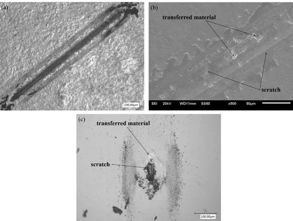
The analysis of uncoated substrate wear tracks showed typical scratch marks of abrasive wear both on the track (Fig. 10a) and on the counterface side (Fig. 10b). Material transferred to the counterface sur face (Fig. 10b), typical of adhesive wear, was also observed. Considering these two phenomena the wear mechanism of the substrate was a mix ture of abrasive and adhesive wear, as expected for wear of metallic ma terials[56].
The appearance of the wear tracks and the alumina counterface for the coated system indicated the same mechanism observed for uncoat ed substrate, scratch marks of abrasive wear can be viewed in SEM
Fig. 11. Appearance offilm obtained from DMF wear: (a) optical image of track; (b) SEM image of track; (c) counterface.
Fig. 12. Appearance of wear tracks: (a) DMF30LI; (c) DMF50LI; (e) DMF100LI; and
image (Fig. 11b). However, there was a reduced wear evidenced by the large reduction in track width (Fig. 11a) and the abraded area in the alu mina ballFig. 11c). There appears to be less amount of material trans ferred to the counterface, as shown inFig. 11c.
The addition of ionic liquid to the electrolyte resulted to a change in the wear mechanism: without scratch marks of abrasive wear (Fig. 12a, c and e), both in thefilm and in the counterface. While the analysis of the counterface (Fig. 12b,d and f) shows adhered material, indicating adhesive wear mechanism, with presence of debris shifted to the ex tremities of the abraded area. This change of wear mechanism may be associated with more elastic character of these coatings as shown by the interfacial behavior analysis (Table 3).
Comparative analysis of wear tracks and counterfaces (Fig. 13) showed that, regardless the presence and amount of ionic liquid, there was no significant change in the width of the wear tracks. On the other hand, an increase in the abraded area of the sphere was observed with addition of small amounts of dopant, and an even greater increased
with the addition of larger amounts of dopant. This phenomena is in good agreement with the increase of the contact area due to the reduc tion of Young modulus predicted by the Hertz contact model. The ex pected contact diameters for the test configurations are between 0.63μm and 0.65 μm, in concordance with de values reached for the track width of the coated systems.
This increase of abraded area could be related with the amount of sp2hybridizations in thefilm, the displacement of G band to lower wavelengths evoked the reduction of amount and size of graphite clusters in thefilm, this reduction limited the lubricating character istics, increasing counterface wear.Fig. 14shows that additions of small amounts of dopant led a significant influence in graphite clus ters, which means there was an important increase in counterface wear.
4. Conclusions
Thefilms obtained had typical characteristics of amorphous carbon structure, formed by sp3and sp2bonds and presence of graphite clus ters. Ionic liquid influenced the structure of the film, probably increasing the amount of sp3bonds and reducing the amount sp2hybridizations, even if a more detailed and in depth Raman analysis, beyond the scope of this paper, would be necessary to better understand the coating structure. This amorphous carbon nature gave thefilm interesting prop erties with regard to wear resistance, reducing the COF for much lower (0.25) than the uncoated substrate values (0.7). An optimum combina tion between the amount of sp2and sp3hybridization was observed for thefilms obtained from DMF with 0.05% of 2HEAL, resulting the lowest COF value, which was accompanied by intermediate wear against the face of alumina.
It was observed good adhesion between thefilm and the substrate, which showed only lateral pile up pad formation without delamination, regardless the presence or absence of dopant in the deposition solution. The ionic liquid addition led to an increased resistance to lateral pile up pad formation, which was observed to four times higher loads for sys tems containing dopant. Furthermore, addition of dopant modified elastoplastic character of thefilms, being observed an increase in the percentage of elastic work with the amount of ionic liquid, this influ enced the wear mechanism, reducing the abrasive nature and leading to a more adhesive nature for the wear, possibly allowing easier tribofilm formation. No clear evidence of hardness evolution could be shown but there was a tendency of reduction of Young modulus with increasing amount of dopant, in good agreement with the increase of the elastic recovery obtained by scratch tests.
Acknowledgements
The authors would like to thank the Brazilian and French scientific funding agencies: CAPES, CNPq and CNRS forfinancial and scientific support this research.
References
[1] J. Jiang, R.D. Arnell, J. Tong, Some special tribological features of DLC coatings depos-ited on soft substrates, Wear 211 (1997) 254–264.
[2] L. Mohan, C. Anandan, V.K.W. Grips, Corrosion behavior of titanium alloy Beta-21S coated with diamond like carbon in Hank's solution, Appl. Surf. Sci. 258 (2012) 6331–6340,http://dx.doi.org/10.1016/j.apsusc.2012.03.032.
[3] P.A. Radi, F.R. Marciano, D.A. Lima-Oliveira, L.V. Santos, E.J. Corat, V.J. Trava-Airoldi, Influence of crystalline diamond nanoparticles on diamond-like carbon friction be-havior, Appl. Surf. Sci. 257 (2011) 7387–7393,http://dx.doi.org/10.1016/j.apsusc. 2011.02.034.
[4] F. Platon, P. Fournier, S. Rouxel, Tribological behaviour of DLC coatings compared to different materials used in hip joint prostheses, Wear 250 (2001) 227–236,http:// dx.doi.org/10.1016/S0043-1648(01)00651-2.
[5] M. Tokoro, Y. Aiyama, M. Masuko, A. Suzuki, H. Ito, K. Yamamoto, Improvement of tribological characteristics under water lubrication of DLC-coatings by surface polishing, Wear 267 (2009) 2167–2172,http://dx.doi.org/10.1016/j.wear.2009.04. 009.
[6] A.M. Gallardo-Moreno, M.A. Pacha-Olivenza, L. Saldaña, C. Pérez-Giraldo, J.M. Bruque, N. Vilaboa, M.L. González-Martín, In vitro biocompatibility and bacterial ad-hesion of physico-chemically modified Ti6Al4V surface by means of UV irradiation, Acta Biomater. 5 (2009) 181–192,http://dx.doi.org/10.1016/j.actbio.2008.07.028. [7] A. Bandyopadhyay, F. Espana, V.K. Balla, S. Bose, Y. Ohgami, N.M. Davies, Influence of
porosity on mechanical properties and in vivo response of Ti6Al4V implants, Acta Biomater. 6 (2010) 1640–1648,http://dx.doi.org/10.1016/j.actbio.2009.11.011. [8] A. Calzado-Martín, A. Méndez-Vilas, M. Multigner, L. Saldaña, J.L. González-Carrasco,
M.L. González-Martín, N. Vilaboa, On the role of RhoA/ROCK signaling in contact guidance of bone-forming cells on anisotropic Ti6Al4V surfaces, Acta Biomater. 7 (2011) 1890–1901,http://dx.doi.org/10.1016/j.actbio.2010.11.035.
[9] T.M. Manhabosco, S.M. Tamborim, C.B. dos Santos, I.L. Müller, Tribological, electro-chemical and tribo-electroelectro-chemical characterization of bare and nitrided Ti6Al4V in simulated bodyfluid solution, Corros. Sci. 53 (2011) 1786–1793,http://dx.doi. org/10.1016/j.corsci.2011.01.057.
[10] J.C. Fanning, Properties of TIMETAL 555 (Ti-5Al-5Mo-5V-3Cr-0.6Fe), J. Mater. Eng. Perform. 14 (2005) 788–791,http://dx.doi.org/10.1361/105994905X75628. [11] P.-J. Arrazola, A. Garay, L.-M. Iriarte, M. Armendia, S. Marya, F. Le Maître,
Machinabil-ity of titanium alloys (Ti6Al4V and Ti555.3), J. Mater. Process. Technol. 209 (2009) 2223–2230,http://dx.doi.org/10.1016/j.jmatprotec.2008.06.020.
[12] T. Nakamura, T. Ohana, Photochemical modification of DLC films with oxygen func-tionalities and their chemical structure control, Diam. Relat. Mater. 33 (2013) 16–19,http://dx.doi.org/10.1016/j.diamond.2012.12.013.
[13] S.-Y. Chen, K.-L. Ou, W.-C. Huang, K.-T. Chu, S.-F. Ou, Phase transformation of dia-mond-like carbon/silver compositefilms by sputtering deposition, Ceram. Int. 39 (2013) 2575–2580,http://dx.doi.org/10.1016/j.ceramint.2012.09.019.
[14] O.V. Penkov, V.E. Pukha, E.N. Zubarev, S.-S. Yoo, D.-E. Kim, Tribological properties of nanostructured DLC coatings deposited by C60 ion beam, Tribol. Int. 60 (2013) 127–135,http://dx.doi.org/10.1016/j.triboint.2012.11.011.
[15] M.F.B. Abdollah, Y. Yamaguchi, T. Akao, N. Inayoshi, N. Miyamoto, T. Tokoroyama, N. Umehara, Deformation–wear transition map of DLC coating under cyclic impact loading, Wear 274–275 (2012) 435–441,http://dx.doi.org/10.1016/j.wear.2011.11. 007.
[16] Y. Namba, Attempt to grow diamond phase carbonfilms from an organic solution, J. Vac. Sci. Technol. Vac. Surf. Films. 10 (1992) 3368,http://dx.doi.org/10.1116/1. 577829.
[17] H.-S. Zhu, J.-T. Jiu, Q. Fu, H. Wang, C.-B. Cao, Aroused problems in the deposition of diamond-like carbonfilms by using the liquid phase electrodeposition technique, J. Mater. Sci. 38 (2003) 141–145,http://dx.doi.org/10.1023/A:1021130303447. [18] K. Cai, D. Guo, Y. Huang, H. Zhu, Evaluation of diamond-like carbonfilms deposited
on conductive glass from organic liquids using pulsed current, Surf. Coat. Technol. 130 (2000) 266–273,http://dx.doi.org/10.1016/S0257-8972(00)00698-8. [19] H. Pang, X. Wang, G. Zhang, H. Chen, G. Lv, S. Yang, Characterization of diamond-like
carbonfilms by SEM, XRD and Raman spectroscopy, Appl. Surf. Sci. 256 (2010) 6403–6407,http://dx.doi.org/10.1016/j.apsusc.2010.04.025.
[20] Y. Li, G. Zhang, X. Hou, D. Deng, Synthesis and tribological properties of diamond-like carbonfilms by electrochemical anode deposition, Appl. Surf. Sci. 258 (2012) 6527–6530,http://dx.doi.org/10.1016/j.apsusc.2012.03.070.
[21] J. Fuller, The room temperature ionic liquid 1-ethyl-3-methylimidazolium tetrafluo-roborate: electrochemical couples and physical properties, J. Electrochem. Soc. 144 (1997) 3881,http://dx.doi.org/10.1149/1.1838106.
[22] D. Santos, F. Costa, E. Franceschi, A. Santos, C. Dariva, S. Mattedi, Synthesis and physico-chemical properties of two protic ionic liquids based on stearate anion, Fluid Phase Equilib. 376 (2014) 132–140,http://dx.doi.org/10.1016/j.fluid.2014.05. 043.
[23] M. Roy, A.K. Dua, A.K. Satpati, Electro-deposition of adherentfilms of H2-free quality diamond-like carbon materials on SS-304 substrates using nanocrystalline SnO2 in-terlayer, Diam. Relat. Mater. 14 (2005) 60–67,http://dx.doi.org/10.1016/j.diamond. 2004.06.040.
[24] J.-T. Jiu, L.-P. Li, C.-B. Cao, H.-S. Zhu, Deposition of diamond-like carbonfilms by using liquid phase electrodeposition technique and its electron emission properties, J. Mater. Sci. 36 (2001) 5801–5804,http://dx.doi.org/10.1023/A:1012951904662. [25] R.S. Li, B. Liu, M. Zhou, Z.X. Zhang, T. Wang, B.A. Lu, E.Q. Xie, Effect of deposition
volt-age on thefield emission properties of electrodeposited diamond-like carbon films, Appl. Surf. Sci. 255 (2009) 4754–4757,http://dx.doi.org/10.1016/j.apsusc.2008.10. 053.
[26]A. Ispas, A. Bund, Electrodeposition in ionic liquids, Electrochem. Soc. Interface 47 (2014).
[27] P.K. Lai, M. Skyllas-Kazacos, Electrodeposition of aluminium in aluminium chloride/ 1-methyl-3-ethylimidazolium chloride, J. Electroanal. Chem. Interfacial Electrochem. 248 (1988) 431–440,http://dx.doi.org/10.1016/0022-0728(88)85103-9. [28] J.A. Mitchell, Electrodeposition of cobalt and cobalt-aluminum alloys from a room
temperature chloroaluminate molten salt, J. Electrochem. Soc. 143 (1996) 3448,
http://dx.doi.org/10.1149/1.1837235.
[29] W.R. Pitner, Electrodeposition of nickel-aluminum alloys from the aluminum chlo-ride-1-methyl-3-ethylimidazolium chloride room temperature molten salt, J. Electrochem. Soc. 143 (1996) 130,http://dx.doi.org/10.1149/1.1836397. [30] D.F. Kennedy, C.J. Drummond, Large aggregated ions found in some protic ionic
liq-uids, J. Phys. Chem. B 113 (2009) 5690–5693,http://dx.doi.org/10.1021/jp900814y. [31] S. Mattedi, P.J. Carvalho, J.A.P. Coutinho, V.H. Alvarez, M. Iglesias, High pressure CO2 solubility in N-methyl-2-hydroxyethylammonium protic ionic liquids, J. Supercrit. Fluids 56 (2011) 224–230,http://dx.doi.org/10.1016/j.supflu.2010.10.043. [32] D. Beeman, J. Silverman, R. Lynds, M.R. Anderson, Modeling studies of amorphous
carbon, Phys. Rev. B 30 (1984) 870–875,http://dx.doi.org/10.1103/PhysRevB.30.870. [33] R.O. Dillon, J.A. Woollam, V. Katkanant, Use of Raman scattering to investigate disor-der and crystallite formation in as-deposited and annealed carbonfilms, Phys. Rev. B 29 (1984) 3482–3489,http://dx.doi.org/10.1103/PhysRevB.29.3482.
[34] A.C. Ferrari, J. Robertson, Interpretation of Raman spectra of disordered and amor-phous carbon, Phys. Rev. B 61 (2000) 14095–14107,http://dx.doi.org/10.1103/ PhysRevB.61.14095.
[35] W.C. Oliver, G.M. Pharr, An improved technique for determining hardness and elas-tic modulus using load and displacement sensing indentation experiments, J. Mater. Res. 7 (1992) 1564–1583,http://dx.doi.org/10.1557/JMR.1992.1564.
[36] J. Zhang, L. Huang, L. Yu, P. Zhang, Synthesis and tribological behaviors of diamond-like carbonfilms by electrodeposition from solution of acetonitrile and water, Appl. Surf. Sci. 254 (2008) 3896–3901,http://dx.doi.org/10.1016/j.apsusc.2007.12.029. [37] S. Gupta, M. Pal Chowdhury, A. Pal, Synthesis of DLCfilms by electrodeposition
tech-nique using formic acid as electrolyte, Diam. Relat. Mater. 13 (2004) 1680–1689,
http://dx.doi.org/10.1016/j.diamond.2004.02.006.
[38] S. Gupta, M.P. Chowdhury, A. Pal, Field emission characteristics of diamond-like car-bonfilms synthesized by electrodeposition technique, Appl. Surf. Sci. 236 (2004) 426–434,http://dx.doi.org/10.1016/j.apsusc.2004.05.014.
[39] T.J. Dines, D. Tither, A. Dehbi, A. Matthews, Raman spectra of hard carbonfilms and hard carbonfilms containing secondary elements, Carbon 29 (1991) 225–231.
[40] C. Cao, H. Zhu, H. Wang, Electrodeposition diamond-like carbonfilms from organic liquids, Thin Solid Films 368 (2000) 203–207.
[41] T.M. Manhabosco, I.L. Muller, Electrodeposition of diamond-like carbon (DLC)films on Ti, Appl. Surf. Sci. 255 (2009) 4082–4086,http://dx.doi.org/10.1016/j.apsusc. 2008.10.087.
[42] R.S. Li, E.Q. Xie, M. Zhou, Z.X. Zhang, T. Wang, B.A. Lu, Field emission properties of nitrogen incorporated DLCfilms prepared by electrodeposition, Appl. Surf. Sci. 255 (2008) 2787–2790,http://dx.doi.org/10.1016/j.apsusc.2008.08.010.
[43]J. Robertson, Diamond-like amorphous carbon, Mater. Sci. Eng. R. Rep. 37 (2002) 129–281.
[44] R. Boyer, G. Welsch, E.W. Collings, American Society for Metals, Materials Properties Handbook: Titanium Alloys, ASM International, Metals Park, Ohio, 1994.
[45]ASM Metals Handbook - Vol 02 - Properties and Selection: Nonferrous Alloys and Special-Purpose Materials, 10th ed. ASM International, 2004.
[46] X.B. Yan, T. Xu, G. Chen, H.W. Liu, S.R. Yang, Effect of deposition voltage on the mi-crostructure of electrochemically deposited hydrogenated amorphous carbonfilms, Carbon 42 (2004) 3103–3108,http://dx.doi.org/10.1016/j.carbon.2004.07.016. [47] Y.J. Won, H. Ki, Effect offilm gradient profile on adhesion strength, residual stress
and effective hardness of functionally graded diamond-like carbonfilms, Appl. Surf. Sci. 311 (2014) 775–779,http://dx.doi.org/10.1016/j.apsusc.2014.05.161. [48] D. Hofmann, S. Kunkel, K. Bewilogua, R. Wittorf, From DLC to Si-DLC based layer
sys-tems with optimized properties for tribological applications, Surf. Coat. Technol. 215 (2013) 357–363,http://dx.doi.org/10.1016/j.surfcoat.2012.06.094.
[49] P.W. Shum, Z.F. Zhou, K.Y. Li, To increase the hydrophobicity, non-stickiness and wear resistance of DLC surface by surface texturing using a laser ablation process, Tribol. Int. 78 (2014) 1–6,http://dx.doi.org/10.1016/j.triboint.2014.04.026. [50] H.C. Thejaswini, A.R. Hoskinson, B. Agasanapura, M. Grunde, J. Hopwood, Deposition
and Characterization of Diamond-Like Carbon Films by Microwave Resonator Microplasma at One Atmosphere, Diam. Relat. Mater. (2014)http://dx.doi.org/10. 1016/j.diamond.2014.06.004.
[51] ASM Handbook Committee, Properties and Selection–Irons and Pure Metals, Amer-ican Society for Metals, Metals Park, Ohio, 1978.
[52] J.-W. Chung, C.-S. Lee, D.-H. Ko, J.H. Han, K.Y. Eun, K.-R. Lee, Biaxial elastic modulus of very thin diamond-like carbon (DLC)films, Diam. Relat. Mater. 10 (2001) 2069–2074,http://dx.doi.org/10.1016/S0925-9635(01)00481-2.
[53] V. Jardret, H. Zahouani, J.L. Loubet, T.G. Mathia, Understanding and quantification of elastic and plastic deformation during a scratch test, Wear 218 (1998) 8–14,http:// dx.doi.org/10.1016/S0043-1648(98)00200-2.
[54] B. Bhushan, Principles and Applications of Tribology, John Wiley & Sons, 1999.
[55] L. Yang, A. Neville, A. Brown, P. Ransom, A. Morina, Friction reduction mechanisms in boundary lubricated W-doped DLC coatings, Tribol. Int. 70 (2014) 26–33,
http://dx.doi.org/10.1016/j.triboint.2013.09.020.
[56] G.W. Stachowiak, Engineering Tribology, third ed. Elsevier Butterworth-Heinemann, Amsterdam; Boston, 2005.