OATAO is an open access repository that collects the work of Toulouse
researchers and makes it freely available over the web where possible
Any correspondence concerning this service should be sent
to the repository administrator:
[email protected]
This is an author’s version published in: http://oatao.univ-toulouse.fr/27751
To cite this version:
Nascimento, Hugo and Mujica, Martin and Benoussaad,
Mourad Collision avoidance in human-robot interaction using
kinect vision system combined with robot’s model and data. (2020)
In: 2020 IEEE/RSJ International Conference on Intelligent Robots
and Systems (IROS), 24 October 2020 - 24 January 2021 (Las
Vegas, United States).
Collision Avoidance in Human-Robot Interaction Using Kinect Vision
System Combined With Robot’s Model and Data
Hugo Nascimento1,2, Martin Mujica2 and Mourad Benoussaad2
Abstract— Human-Robot Interaction (HRI) is a largely ad-dressed subject today. Collision avoidance is one of main strategies that allow space sharing and interaction without contact between human and robot. It is thus usual to use a 3D depth camera sensor which may involves issues related to occluded robot in camera view. While several works overcame this issue by applying infinite depth principle or increasing the number of cameras, we developed in the current work a new and an original approach based on the combination of a 3D
depth sensor (Microsoft Kinect V2) and the proprioceptiveR
robot position sensors. This method uses a principle of limited safety contour around the obstacle to dynamically estimate the robot-obstacle distance, and then generate the repulsive force that controls the robot. For validation, our approach is applied in real time to avoid collision between dynamical obstacles (humans or objects) and the end-effector of a real 7-dof Kuka LBR iiwa collaborative robot.
Several strategies based on distancing and its combination with dodging were tested. Results have shown a reactive and efficient collision avoidance, by ensuring a minimum
obstacle-robot distance (of ≈ 240mm), even when the robot is in an
occluded zone in the Kinect camera view.
I. INTRODUCTION
Humans and robots working together or sharing the same space could reach an extraordinary level of performance if they combine the human decision-making capabilities and the robot’s efficiency [1], [2], however, this collaboration has to be safe for humans beings.
Human-Robot Interaction (HRI) is a novel and promising trend in robotics research, since an increasing number of works were addressed in this field [3], [4]. One aspect of HRI is physical Human-Robot Interaction (pHRI), which deals with the collision detection [5] and a continuous physical interaction [6]. Another aspect of HRI is collision avoidance, where the robot adapts its predefined trajectory to avoid collision with dynamic obstacles (humans or objects) [7], [8], [9], [10]. Collision Avoidance using human wearable sen-sors were explored in [10]. However, this solution presents the equipment complexity and thus limits the interacting people number. Furthermore, collision avoidance based on 3D depth camera (Microsoft Kinect) were explored [7], [8], [9]. In these works, it is usual to retract the robot from the scene to detect and track only obstacles. Authors in [7] explored the depth space to compute distances between the robot and dynamic obstacles in real-time and then, the
1 Hugo N. Author is with Polytechnic school, Automation and control
department, University of Pernambuco, R. Benfica, 455 - Madalena, Recife
- PE, 50720-001. Brazil;[email protected]
2 Martin M. and Mourad B. authors are with LGP-ENIT,
University of Toulouse, Tarbes, France; {martin.mujica,
mourad.benoussaad}@enit.fr
robot was controlled using virtual repulsive forces principle. The obstacle-robot distance estimation methods were more deeply explored in [11] by developing an improved and faster method for a real time application.
However, using Kinect implies robot occlusion issues when the obstacle is between the robot and the camera. To overcome these issues, different approaches were ex-plored. One approach used multiple Kinects to increase the workspace representation. Authors of [8], [9] used two Kinects in a similar way, however authors in [9] applied a collision avoidance of a 6-dof robot manipulator, while keeping its task by including Cartesian constraints. Further-more, the use of multiple Kinects, increases the calibration complexity between them and the computational cost.
Other approach using one Kinect only, considered the obstacle with an infinite depth, called a gray area [6], [7], [11]. Although this approach highlighted efficient results and prioritized the human safety, it presents a too conservative behavior. For instance, when the obstacle is placed between the robot and the camera, it will be considered close to the robot even when it is far from it in the depth axis, and thus it can not deal with the case of obstacles that hide completely the robot from the camera’s view. Moreover, all these previous works that used Kinect to extract the robot pose had to manage the unavoidable noise that comes from the vision system.
In the current work, we explore a new approach for col-lision avoidance between dynamic obstacles and the robot’s End-Effector (E-E), which can be completely hidden by ob-stacles. Our method differs from previous works, for dealing with this case, by merging the robot kinematic model and its proprioceptive data in the 3D depth data of the environment. Moreover, as an alternative to infinite depth strategy [7], [11] and its above-mentioned issues, we applied a limited
safety contouraround the obstacle to avoid unnecessary robot movement and deal with the case of hidden robot’s E-E.
In the next Section an overview of the system and the description of the materials are presented. Then our collision avoidance approach is described in Section III. Results are presented and discussed in Section IV, then a conclusion and the perspectives of this work are summarized in Section V.
II. MATERIALS AND SYSTEM OVERVIEW This section describes the whole system overview (hard-ware/software) and introduces the Kinect’s depth principle and the collaborative robot used.
!"#$%&'"()) %*+$,)
Fig. 1: Collision avoidance system overview.
A. Whole system overview
The whole system overview is illustrated by Fig. 1. It includes a Perception system and a Control system which works in a real-time closed-loop. The perception combines vision acquisition through Kinect {1} and the robot pose using joint angles{2} along with its kinematic model {3}. This robot pose is projected in the depth space using data fusion{4}, which allow removing the robot from the image. Then the obstacle’s nearest point to the robot in a supervised
zoneis detected{5} and its coordinates are filtered using a Kalman filter {6} to handle the noise related to the depth image. The distance between the obstacle’s nearest point and the robot’s E-E is used in the control part, by generating a repulsive vector {7} to control and adapt the robot posture {8} in order to avoid collisions with dynamic obstacles.
B. Kinect and depth space representation
The used Kinect V2 is placed in the range between0.5m and4.5m from robot, where the maximum data rate is about 30Hz. From depth image (grayscale image of 512 × 424 resolution) [12], (1) is used to get a point in the Kinect’s frame from its pixel address on the depth image.
xr = (xi− cx)dp/fx yr= (cy− yi)dp/fy zr = dp (1)
Wherecx andcy are the coordinates of a so-called generic
Cartesian point in X and Y axis, fx and fy are the focal
lengths along X and Y axis and dp is the depth of the
pixel.(xi,yi) are coordinates of the pixel on the image and
(xr, yr, zr) represents real point coordinates in the Kinect
frame.
C. Collaborative robot and practical aspects
A 7-dof redundant manipulator (Kuka LBR Iiwa R820 collaborative robot) has been used. To control the robot and get its proprioceptive data using an external system in real time, Fast Robot Interface (FRI) software option was adapted and used [13]. The FRI control is based on an
overlay principle which consists of superposing a control input, derived from the external system (with our method), and a local robot control law.
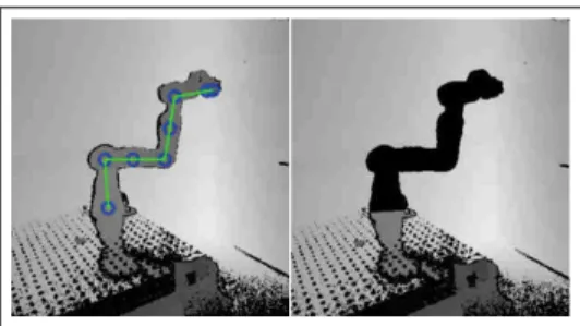
Fig. 2: Robot depth image with its skeleton (left) and after the its extraction from image (right).
III. COLLISION AVOIDANCE STRATEGIES This section describes the used methodology. It starts from the perception of the robot and environment until the control law, following steps presented in Fig. 1.
A. Robot Kinematic model
Kinematic model of our robot was established from [14]. It is used to describe and update the robot’s pose (a skeleton of Fig. 2-left) from the measured robot’s joint angles (FRI §II-C). Hence, the robot pose is updated in real-time, even when the Kinect camera does not see it (robot in occluded zone).
B. Depth image and robot intrinsic data fusion
To handle the obstacle-robot collision, it is necessary to know what points correspond to the robot in order to consider all the other points as corresponding to the environment (possible obstacles). Indeed, if a point of the robot is not identified and removed from image, it can be considered as a possible obstacle, particularly if it is in a supervised
zone. Therefore, with the kinematic model and joint angles, a robot skeleton was implemented and updated, as a real robot, on the 3D depth image, which makes possible the robot identification. This skeleton augmented with a predefined 3D robot form is then used to remove it from the image and obtaining a depth image without the robot. These steps are illustrated by Fig. 2, where the left side shows the robot skeleton added to the depth image, and the right side shows the depth image with the robot removed. However, these steps are possible if a robot data fusion is done between a depth image space and its intrinsic data. This data fusion consists of linking the robot skeleton, updated from its intrinsic data and model, with points of robot (or a visible part) in the image. Hence, a precise representation between Kinect frame and the robot frame is required. For that, an offline calibration procedure was implemented using the three known points technique [15].
C. Nearest point: searching and filtering
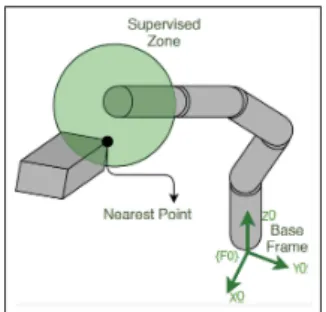
A supervised zone, where an obstacle is searched, was chosen and implemented as a spherical shape, which center is the robot’s E-E, as illustrated by Fig. 3. The method searches in the depth image inside this sphere for the obstacle nearest point from the sphere center (Fig. 3). The collision
Fig. 3: Supervised zone and its nearest point.
avoidance strategy is based on the position of this point with respect to (w.r.t.) the robot’s E-E, which makes its estimation quality very important for robot control and smooth motion. Therefore, to ensure this estimation quality, this point’s position was filtered with a Kalman filter since it is known to be fast, optimal and lite [16]. To apply this Kalman filter, a constant velocity model [9] of point motion was adopted and implemented.
D. Distance evaluation
Our approach of collision avoidance is based on robot-obstacle distance estimation. It is calculated using Euclidean distance d1 between obstacle nearest point Po (see
§III-C) and a robot E-E point Pe (see §III-B). To consider the
occlusion risk of the robot by the obstacle, we distinguish two use cases (Fig. 4):
Case 1: No occlusion risk. When the obstacle has a greater depth than the robot E-E (z1 > ze) in the camera
point of view (Fig. 4-Case 1), the distanced1 is used in the
collision avoidance method.
Case 2: risk of occlusion. When the obstacle has a lower depth than the robot E-E (ze > z1), there is a risk of
occlusion. In this case, we do not consider infinite depth strategy for the obstacle as in [7]. Instead, we used a safety
contour around the point that we are dealing with (visible nearest point), as shown by Fig. 4-Case 2. Hence, we limit the influence of obstacle on the robot, even keeping a safety distance:
d2= d1− R (2)
Where d1 is calculated as mentioned before and R is the
radius of the safety contour. The choice of its value is based on the rough estimation of the obstacle (or the human hand) size, by considering the longest distance between two points of it. Hence, In case 2, it is the safety distanced2which is
used in collision avoidance method.
E. Potential field
To ensure collision avoidance of the robot with dynamic obstacles, the potential field method was applied [17]. In this method, the dynamic obstacle creates a repulsive force which is used here through two strategies: Distancing and
Dodging. These strategies are based on intuitive human collision avoidance (example of bullfight).
Distancing strategy: It is an intuitive method that consists of distancing the robot from the obstacle in the same line than
Kinect z1 ze Distance - Point of interest to obstacle point Obstacle Point Point of Interest Kinect z1 ze Distance - Point of interest to obstacle point Obstacle Point Point of Interest Safety Contour Case 1 Case 2
Fig. 4: Methods for distance evaluation (two cases). Case 1: no risk of occlusion. Case 2: with risk of occlusion
Fig. 5: Distancing strategy principle.
vector−→d , which links the obstacle to robot E-E, by applying a repulsive force as illustrated by Fig. 5.
The model of repulsive force is defined as in [7]: −→ F 1 = − → d k−→d k V (3)
WhereV is the force intensity defined as an inverted sigmoid function of the distance between obstacle and robot’s E-E:
V = Vmax
1 + e(k−→d k (2/ρ)−1)α (4)
Vmaxis the maximal force intensity,α a shape factor and ρ a
parameter related to the supervised zone size [7]. Therefore, the repulsive force intensity V will be Vmax when
robot-obstacle distance vanish, and should approach zero when the distance reaches supervised zone limits, since the force is not defined beyond.
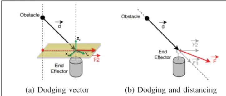
Dodging strategy: In this technique, instead of moving like the obstacle and in the same direction, the end-effector dodges the obstacle by moving in another direction thanks to the Cartesian force−→F 2 (see Fig. 6a). In the current work, this direction is chosen to be on the plan(Xe, Ye) (in yellow)
of the robot’s E-E frame (Fig. 6a), whereZeis the axis of
the last joint robot. Therefore, the force−→F 2 is given by the equation: −→ F 2 = −−−−−→ P roj(d)(Xe,Ye) k−−−−−→P roj(d)(Xe,Ye)k V (5)
Xe Ye
Ze
Ye
(a) Dodging vector (b) Dodging and distancing
Fig. 6: Dodging and distancing combination strategy.
Where−−−−−→P roj(d)(Xe,Ye)is the projection of vector
− →
d in the plan(Xe, Ye) and V is the repulsive force intensity defined
by (4). A generalization of this dodging strategy is made here in practice. In fact, a Cartesian force applied on the robot’s E-E is actually−→F , which is a linear combination of
distancingvector −→F 1 and dodging vector−→F 2, as illustrated by Fig. 6b and described by (6):
− →
F = β1−→F 1 + β2−→F 2 (6)
Whereβ1andβ2are parameters to adjust to give the robot
more distancing or more dodging behavior, as required by the application.
For both strategies, the calculated repulsive force was applied as a wrench (Cartesian forces) at the robot E-E. In Kuka LBR iiwa, this wrench is superposed to an existing local control law, by using FRI software tool (§II-C).
IV. EXPERIMENTAL RESULTS AND DISCUSSION In this section, experimental tests and results of the collision avoidance strategies are presented and discussed to analyze and assess our proposed method. The experimental setup includes a 7-dof Kuka LBR Iiwa with its controller, a Kinect V2 and an external computer (Intel Core i7; 2.5Ghz × 8; 16 GiB Memory; NVIDIA Quadro K2100M
as graphics; Ubuntu 18.04 as OS). Kinect was placed on a rigid support at 2.346m from the robot, precisely in the robot coordinate (140mm, 431mm, 2302mm).
Parameters of our methods and strategies defined above can be adjusted for each application purpose. However, they were adjusted in the current experiment as follows. The
supervised zonediameter value is fixed to 1.1m and safety contour radius R = 150mm (based on the obstacle’s size knowledge); Parameters of force intensity function of (4) are α = 5.0, ρ = 0.425 and V max = 45.0N ; Parameters of forces linear combination of (6) areβ1= 1.8 and β2= 1.0.
The way to adjust β1 and β2 can be explored in future
works, meanwhile it is experimentally adjusted and fixed in the current work to test the method.
The background task (robot task when there is no obstacle) is to keep its initial configuration with a compliant Cartesian behavior in translation (i.e. with a virtual Cartesian mass-spring-damper system) using an impedance controller of Kuka LBR iiwa [18]. For the three axis, the stiffness was fixed to 300N/m and the damping ratio to 1. Then, our
t = 1.445s t = 2.411s t = 5.278s
t = 7.178s t = 8.115s t = 10.00s
Fig. 7: Images sequence of collision avoidance test with the robot in an occluded zone.
collision avoidance strategies and robot control overlay (i.e. external control superposed to local robot control) were applied at a wrench level through FRI command mode in real time.
In the following experiments, distancing strategy is ap-plied when robot is in an occluded zone to highlight our method robustness. Then a test with multiple and repetitive collision avoidance is proposed to show results reproducibil-ity and finally, the dodging strategy is tested and analyzed. Results are then discussed where dodging and distancing strategies are compared.
A. Collision avoidance with the robot in an occluded zone
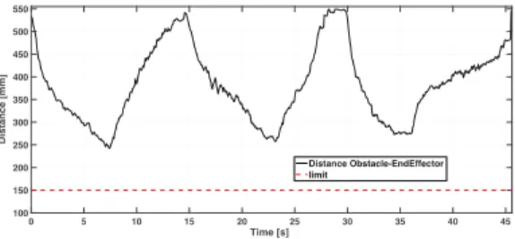
In the current test, a Cardboard box (dynamic obstacle) was used to move toward the robot E-E, while keeping it in an occluded zone. Hence, the robot’s E-E remains behind the obstacle w.r.t. the Kinect viewpoint. Fig. 7 shows an images sequence of this experiment, where a RGB image is the main picture and a grayscale image (Kinect viewpoint) with a robot skeleton is at the top-right. We can notice in the grayscale images that the robot is hidden behind the cardboard box w.r.t. Kinect. Results of this test, presented in Fig. 8, show the evolution of the obstacle-robot’s E-E distance while the robot is in an occluded zone. It highlights that this distance never cross the limit of150mm (red line), which corresponds to safety contour radius (R).
0 5 10 15 20 25 30 35 40 45 Time [s] 150 200 250 300 350 400 450 500 550
Distance [mm] Distance Obstacle-EndEffector
limit
Fig. 8: Obstacle-Robot E-E distance evolution during the test with the robot in an occluded zone and distance limit (red).
B. Multiple collision avoidance
As mentioned before, the current test purpose is to explore reproducibility of our solution. It was realized in the same conditions and with the same strategy (distancing) than the previous test. Fig. 9 shows the evolution of the obstacle-Robot’s E-E distance for multiple collision attempts between
0 5 10 15 20 25 30 35 40 45 Time [s] 100 150 200 250 300 350 400 450 500 550 Distance [mm] Distance Obstacle-EndEffector limit
Fig. 9: Evolution of obstacle-Robot E-E distance during multiple collision attempts and distance limit (red).
t = 2.889s t = 5.285s t = 8.819s
t = 12.751s t = 16,852s t = 20.719s
Fig. 10: Images sequence of dodging strategy test.
them. Results highlight that our collision avoidance strategy, by controlling the robot, keep always enough distance from the limit of150mm (red line) even with multiple collision attempts. The minimum distance was at time7.2s and had a value of242mm.
C. Dodging Strategy
In the current test, the obstacle was moved vertically (Z axis) from the bottom in direction of robot E-E in order to analyze the dodging strategy, as illustrated by the images sequence of Fig. 10. In the grayscale part of each image (top-right), the blue line, representing the obstacle-robot’s E-E distance, is firstly almost vertical (att ≈ 2.89s), then it tends to become horizontal (att ≈ 16.85s), which shows that robot dodges the obstacle movement by taking a different direction. To analyze more deeply these results, Fig. 11 highlights the evolution ofY and Z coordinates of the robot’s E-E and the obstacle in the robot base frame{F0} (see Fig. 3). Obstacle Z coordinate increases (vertical movement) until crossing those of robot E-E (at t ≈ 16s), while Y coordinates of both are close at the beginning and diverge thereafter, which is typical of dodging behavior. We can also notice a smallZ coordinate variation of robot E-E, related to the distancing vector−→F 1 in the dodging and distancing combination strat-egy (6). TheX coordinates are not presented since they are not very relevant for this movement which occurs basically on theY and Z directions. Despite crossing of the different coordinates, a certain distance between obstacle and robot
E-Eis respected, avoiding thus the collision, as illustrated by Fig. 12. We can notice that the instant of minimum distance corresponds almost to the one of Z-coordinates crossing (between the robot’s E-E and the obstacle).
D. Discussions
Overall, results highlight robot’s capabilities to avoid collisions with dynamic obstacles, even when it is in an
0 5 10 15 20 25 1.8 2 2.2 2.4 Position [m] Obstacle y Robot y 0 5 10 15 20 25 Time [s] -0.5 0 0.5 1 Position [m] Obstacle z Robot z
Fig. 11:Y and Z coordinates of the obstacle and the robot
E-E. 0 5 10 Time [s] 15 20 25 100 150 200 250 300 350 400 450 500 550 Distance [mm]
Distance Obstacle-End Effector limit
Fig. 12: Obstacle-Robot E-E distance evolution during the
dodgingstrategy test.
occluded zone w.r.t. Kinect. Indeed, the proprioceptive robot data (joint angles), provided by FRI monitor mode in real time, combined with the robot kinematic model allow robot posture estimation with a small uncertainty even without being seen by Kinect. In this case, a safety contour, based on the nearest point detected, was defined (Fig. 4-Case 2) since the real obstacle nearest point may not be visible for the camera either. This allows a less conservative safety strategy than in [7], by assuming roughly the obstacle size knowledge and thus fixing the contour radiusR. As a perspective, this contour radius size can be adapted online by considering also the obstacle speed estimation in the adaptive law. In addition, the robot posture estimation is more stable and does not suffer from the noise that can come from the vision system. However, since the collision avoidance strategy is based on the obstacle-robot distance, vision-based estimation of the obstacle position still presents noise issues. Hence, filtering of these data was required, and done in the current work.
Distancing strategy presented satisfactory and efficient results, however the dodging strategy was conceived to overcome robot space reachability problems, which would appears using distancing strategy. Indeed, when only
distanc-ingstrategy is applied, the robot E-E has a displacement limit since its base is fixed, while dodging strategy takes another direction than obstacle and does not present such an issue. Despite good results of dodging strategy as well, this method can present some limitations related to the dodging vector−→F 2 (6) that vanishes if the vector−→d is perpendicular to the plan (Xe, Ye), canceling thus any dodging action when it is needed
the most. Furthermore, if this vector changes direction when obstacle is too close to E-E (i.e. high force intensity), it can induce a discontinuity on the robot applied wrench. However, it is an unlikely situation since the obstacle’s
natural movement should not lead to it. The two strategies are not completely independent since in dodging strategy there is a weighted vector related to distancing. Therefore, switching between one method to another, can be smooth by adapting vectors weights. In this case, the distance and obstacle’s speed should be further considered to adapt the contribution of each strategy (distancing or dodging) through their vector weights. This adaptation and its strategy should be explored in future works.
A limitation of the repulsive force model with safety
contourappears if the safety distance can not be maintained (e.g. the obstacle’s speed is higher than the maximum speed of the robot’s E-E). In this case the direction of the force (3) still remains the same however, the intensity (4) decreases once the robot’s E-E crosses the contour limits, while it is supposed to keep increasing. In this context, the method faces a dilemma when the robot should avoid collision with fast obstacles while the robot has a limited speed for safety. Therefore, the obstacle speed should be considered in future works to adapt online the size of safety contour, but also adapt online parameters and weights related to distancing or
dodgingstrategies.
Once repulsive forces are calculated, other robot control strategies can be expected (torque control or position control) and are planned in future works. Current work and results present a first step for a different approach of collision avoidance, in the context of hidden robot. This work is already useful when the robot is handling an object or a tool, therefore it is the E-E that should avoid the collisions. However, an extension of this promising strategy to all the robot’s links is planned for future work as well.
V. CONCLUSIONS AND FUTURE WORKS In the current work, an original approach for human-robot collision avoidance was proposed to deal with the situation of the robot being hidden by obstacles. For that, the estimation of the robot’s posture in real time, based on its kinematic model and the proprioceptive data (joint angles), is merged with the Kinect 3D depth data of the environ-ment. This allowed the obstacle-robot distance evaluation in depth space and generates a repulsive force to control the robot at the wrench level. Two main collision avoidance strategies (distancing and dodging) were implemented and tested. Results of both strategies highlighted a good collision avoidance for all tests, which is materialized by a minimum distance of about240mm between obstacle and robot E-E, even when the robot is in an occluded zone (hidden by the obstacle). In future works, other robot control law and the online adaptation of parameters, vector weights and safety contour size to make a robust behavior should be addressed. The collision avoidance between dynamic obstacles and the other robot links should be explored as well.
ACKNOWLEDGMENT
Thanks to the BRAFITEC (Brazil France Technology) program to support this research. In memory of F. Flacco, whose works inspired us for this work.
REFERENCES
[1] J. T. C. Tan, F. Duan, Y. Zhang, K. Watanabe, R. Kato, and T. Arai, “Human-robot collaboration in cellular manufacturing: Design and development,” 2009 IEEE/RSJ International Conference on Intelligent
Robots and Systems, IROS 2009, pp. 29–34, 2009.
[2] J. Kr¨uger, T. K. Lien, and A. Verl, “Cooperation of human and ma-chines in assembly lines,” CIRP Annals - Manufacturing Technology, vol. 58, no. 2, pp. 628–646, 2009.
[3] A. D. Santis, B. Siciliano, A. D. Luca, and A. Bicchi, “An atlas of physical human – robot interaction,” Mechanism and Machine Theory, vol. 43, pp. 253–270, 2008.
[4] R. Alami, A. Albu-Schaeffer, A. Bicchi, R. Bischoff, R. Chatila, A. De Luca, A. De Santis, G. Giralt, J. Guiochet, G. Hirzinger, F. Ingrand, V. Lippiello, R. Mattone, D. Powell, S. Sen, B. Siciliano, G. Tonietti, and L. Villani, “Safe and dependable physical human-robot interaction in anthropic domains: State of the art and challenges,” in
2006 IEEE/RSJ International Conference on Intelligent Robots and Systems, Oct 2006, pp. 1–16.
[5] D. Popov, A. Klimchik, and N. Mavridis, “Collision detection, local-ization & classification for industrial robots with joint torque sensors,”
RO-MAN 2017 - 26th IEEE International Symposium on Robot and Human Interactive Communication, vol. 2017-Janua, no. May 2018, pp. 838–843, 2017.
[6] A. De Luca and F. Flacco, “Integrated control for pHRI: Colli-sion avoidance, detection, reaction and collaboration,” Proceedings of
the IEEE RAS and EMBS International Conference on Biomedical Robotics and Biomechatronics, pp. 288–295, 2012.
[7] F. Flacco, T. Kr¨oger, A. De Luca, and O. Khatib, “A depth space approach to human-robot collision avoidance,” Proceedings - IEEE
International Conference on Robotics and Automation, pp. 338–345, 2012.
[8] B. Schmidt and L. Wang, “Depth camera based collision
avoidance via active robot control,” Journal of Manufacturing
Systems, vol. 33, no. 4, pp. 711–718, 2014. [Online]. Available: http://dx.doi.org/10.1016/j.jmsy.2014.04.004
[9] J.-H. Chen and K.-T. Song, “Collision-Free Motion Planning for Human-Robot Collaborative Safety Under Cartesian Constraint,” 2018
IEEE International Conference on Robotics and Automation (ICRA), pp. 1–7, 2018.
[10] M. Safeea and P. Neto, “KUKA Sunrise Toolbox: Interfacing Col-laborative Robots with MATLAB,” IEEE Robotics and Automation
Magazine, vol. 26, no. 1, pp. 91–96, 2019.
[11] F. Flacco, T. Kroeger, A. De Luca, and O. Khatib, “A Depth Space Approach for Evaluating Distance to Objects: with Application to Human-Robot Collision Avoidance,” Journal of Intelligent and
Robotic Systems: Theory and Applications, vol. 80, pp. 7–22, 2015. [12] O. Wasenm¨uller and D. Stricker, “Comparison of kinect v1 and v2
depth images in terms of accuracy and precision,” Lecture Notes
in Computer Science (including subseries Lecture Notes in Artificial Intelligence and Lecture Notes in Bioinformatics), vol. 10117 LNCS, pp. 34–45, 2017.
[13] K. R. Group, “KUKA Sunrise.Connectivity FRI 1.7. Augsburg, Ger-many, 1st edition,” pp. 1–59, 2015.
[14] C. Gaz and A. De Luca, “Payload estimation based on identified coefficients of robot dynamics - With an application to collision detection,” in IEEE International Conference on Intelligent Robots
and Systems, vol. 2017-Septe, 2017, pp. 3033–3040.
[15] W. Zhang, X. Ma, L. Cui, and Q. Chen, “3 points calibration method of part coordinates for arc welding robot,” in Intelligent Robotics and
Applications, C. Xiong, Y. Huang, Y. Xiong, and H. Liu, Eds. Berlin, Heidelberg: Springer Berlin Heidelberg, 2008, pp. 216–224. [16] S. Y. Chen, “Kalman filter for robot vision: A survey,” IEEE
Transac-tions on Industrial Electronics, vol. 59, no. 11, pp. 4409–4420, Nov 2012.
[17] O. Khatib, “Real-time obstacle avoidance for manipulators and mobile robots,” in Proceedings. 1985 IEEE International Conference on
Robotics and Automation, vol. 2, March 1985, pp. 500–505. [18] A. Albu-Sch¨affer, S. Haddadin, C. Ott, A. Stemmer, T. Wimb¨ock,
and G. Hirzinger, “The DLR lightweight robot: Design and control concepts for robots in human environments,” Industrial Robot, vol. 34, no. 5, pp. 376–385, 2007.