Design and Performances of the Heliospheric Imager
for the STEREO Mission
Emmanuel Mazy
a, Jean-Philippe Halain
a, Jean-Marc Defise
a, Philippe Ronchain
a,
Russel A. Howard
b, J. Daniel Moses
b,
Chris Eyles
c, Richard Harrison
d.
a
Centre Spatial de Liège, Liège Science Park, 4031 Angleur, Belgium
b
Naval Research Laboratory, Washington, DC 20375
c
University of Birmingham, Birmingham B15217, UK
d
Rutherford Appleton Laboratory, Oxfordshire OX11 0QX, UK
ABSTRACT
The Heliospheric Imager (HI) is part of the SECCHI suite of instruments on-board the two STEREO spacecrafts to be launched in 2006. Located on two different orbits, the two HI instruments will provide stereographic images of solar coronal plasma and coronal mass ejections (CME) over a wide field of view (~90°), ranging from 13 to 330 solar radii (R0). These observations complete the 15 R0 field of view of the solar corona obtained with the other SECCHI
instruments (2 coronagraphs and an EUV imager).
The HI instrument is a combination of 2 refractive optical systems with 2 different multi-vanes baffle system. The key challenge of the instrument design is the rejection of the solar disk light, with total straylight attenuation of the order of 10-13 to 10-15. The optics and baffles have been specifically designed to reach the required rejection.
This paper presents the SECCHI/HI opto-mechanical design, with the achieved performances. A test program has been run on one flight unit, including vacuum straylight verification test, thermo-optical performance test and co-alignment test. The results are presented and compared with the initial specifications.
Keywords: Heliospheric imager, straylight, baffling, rejection test
THE HELIOSPHERIC IMAGERS FOR THE STEREO MISSION
The Solar Terrestrial Relations Observatory (STEREO) mission is a NASA program. Two identical spacecrafts will be launched in 2006 and sent into Earth-like orbits, one ahead (A) and one lagging (B) the Earth, providing two vantage points for stereographic observations.
The Sun Earth Connection Coronal and Heliospheric Investigation (SECCHI) is a suite of remote sensing instruments, part of the STEREO payload. The instruments of SECCHI will observe coronal mass ejections (CMEs), as they can look back at the Earth-Sun line and detect the CME as they approach Earth. A detailed description of SECCHI is in ref.[1].
The SECCHI suite includes an Heliospheric Imager (HI) to detect and track the faint emission of CMEs at large distances from the Sun. Within the SECCHI suite, the CMEs will be ideally detected first by the EUV disk imager, then successively by the COR1, COR2 coronagraphs and then by the HI, as the CME is leaving the Sun and becoming fainter.
1. Instrument Concept
The challenges of the HI design are to provide imaging capabilities over very wide field of view (FOV) of ~85° starting at 12 R0 (solar radii), and to
provide faint light detection capability with irradiance levels down to ~10-15 B0 (B0 being the solar
irradiance at 1 AU).
At long elongation from the sun centre the CME signal is extremely faint, requiring a very important stray-light suppression from a lot of different sources. At short angular distance from the Sun, the CME's are rather bright, but the Sun is a very bright extended
source in direct proximity of the field of view (FOV), which requires an extremely performant occultation. Thus this leaded to separate the fields of view in 2 regimes, each one with a specialized optical system and dedicated shading baffles.
2. Optical systems
The HI optical systems have been designed with the parameters of table 1. HI-1 and HI-2 include respectively 4 and 6 lenses, made with glasses selected for their radiation resistance to withstand with the orbital environment. A detailed description of the design can be found in ref. [3].
The design of HI-1 is mainly driven by mechanical constrains on the first lens, which required the smallest possible diameter, while HI-2 was designed for a large FOV, large spectral range and minimum ghost images. The HI-2 optical system was optimised to match exactly the required FOV and the CCD detector area.
HI-1 HI-2
Field of view (FOV): 20 arcdeg diameter
75 R0 diameter
70 arcdeg circular 262 R0 diameter
Focal length: 78.4 mm 19.7 mm
Entrance pupil diameter: 16 mm 7 mm
Spectral range: 630 – 750 nm 400 – 1000 nm
Focal plane: CCD 2048x2048 pixels
13.5 µm pitch
CCD 2048x2048 pixels 13.5 µm pitch
Table 1: HI optical parameters
Wherever possible, antireflection (AR) coatings are used on all the surfaces. The first one, in contact with the outer space, is SiO2-coated, to avoid AR coating ageing as it is submitted to the highest radiation level. In HI-1, the spectral
selection is achieved with a multilayer bandpass coating, applied on 2 internal surfaces with the minimum incidence angles. The large spectral range and the wide incidence range on the HI-2 surfaces are problematic. A MgF2
antireflective coating efficiency is selected. To reduce the impact of ghost images in HI-2, the optics design was specifically optimized to spread the ghost spot on a larger area in the focal plane.
The 2048x2048 pixel CCD detectors are integrated in each of the two focal plane assemblies (FPA) and passively cooled by dedicated external radiators viewing cold space. The CCD readout will be operated in a shutterless mode. The only mechanism present in the instrument is a one-shot aperture cover used to protect the instrument from particle contamination during ground tests and launch ascent. The electronics box is accommodated at the bottom of the sensor box, in direct proximity of the detectors.
Solar light
Forward Baffle
Internal Baffle
HI 1 HI 2
Figure 1: The HI FM-A instrument 3. Stray-light sources
HI is exposed to a set of very different stray-light sources. The sharing in 2 different optical FOVs already results from the different nature of their pertaining bright objects:
- The most intense is the direct solar flux. It mostly affects HI-1 due to its very close vicinity with its FOV, but it is also a concern for HI-2, that requires a very low background level for faint object detection.
- Another bright object is the Earth, that will be initially beyond the border of HI-2 FOV, but that will rapidly enter it and become the brightest object in the scene. The Moon is similar to Earth, both in intensity and trajectory in HI-2 FOV. HI-1 could be affected by stray reflections in its front assembly before the aperture stop. Venus is the brightest planet after the Earth, still brighter than the stars. It will be periodically in the HI-1 & 2 views.
- The SWAVES antenna of the STEREO payload is a concern for HI-2, it is in the direct solar flux and back-scattered solar light is expected on the top surface of the instrument.
All those sources were considered in the design of the baffles. There also remains inherent background light :
- from the K and F corona, that will produce an unavoidable background;
- from the bright source in the FOV, a fraction of which that is partly occulted by the aperture stop, will produce some scattered background in the focal plane area.
Another concern is the over-saturation that will be produced by the brightest objects in the HI-2 FOV: Earth, Moon, and Venus are expected to generate more than hundred times the electron full well, with the nominal exposure time of 60 s. To solve this over-illumination a small local occulter (strip like) has been added in the FPA in order to hide those bright objects.
4. HI-1 and HI-2 straylight protection
The HI instrument includes a set of different baffling systems, each one dedicated to a specific set of sources.
• HI-1 will view the inner heliosphere from 3.65° from the Sun, with a FOV of 20°. Its baffle system is specially designed and optimized to protect the optics from the solar disk emission. The quasi-collimation of the solar flux is a characteristic from which we took advantage to design the shading system. The baffling is thus a 5 vanes cascading diffraction system that protects the optical systems from the direct solar disk light, grazing to the instrument top side. Each successive linear vane has been designed in size and positioning in order to provide, by diffraction, an improved level of shadow. This “front baffle” provides a rejection level of the direct solar flux lower than 10-9 for HI-1 and 10-11 for HI-2, which is a major achievement for the instrument (see [2] and [3]).
• HI-2 has a 70° FOV, starting at 18.36° from the Sun. This wide-angle optical system is surrounded by a classical multivane system that aims to suppress any reflected light from the bright sources reaching the external surfaces of the instrument. Opposed to the front baffle concept, this inner baffle uses the vane geometry and the absorbing properties of the black paint that will cover all the surfaces. The light is damped by absorption and diffuse reflections on black surfaces. This baffle also protects HI-2 from solar light by the HI-1 diffractive baffling system.
forward baffle
HI-1
HI-2 X
Figure 2: Front baffle concept with the location of the
HI-1 & 2 optical systems Figure 3: Inner baffle surrounding HI-2 The lens systems are also potential contributors to stray-light
contamination, with the ghosts that can be produced from multi-reflections on the optical surfaces and stray multi-reflections on the inner surfaces of the lens barrel. This is one of the purposes of the anti-reflective coatings. Special care was taken to enlarge as much as possible the remnants of ghosts that will affect the images of stars, especially for HI-2 with the limited performance of the AR coating with large incidence angles and spectral range. By doing so, the ghost contribution becomes a background noise, and does not generate twin stars with field-dependent spacing.
The design of the inner geometry of the lens barrel has been optimised by ray-trace analysis, and some cavities were added to act as light
traps. A black chromium coating has been selected for the internal surfaces of the titanium lens barrel. This will provide additional absorption of the incident rays out of the FOV, that are partly suppressed by the aperture stop. A general 10-4
attenuation factor has been targeted for all the light that is not focussed on the detector, and partly hidden by the aperture stop.
OPTICAL PERFORMANCE TESTING ON LENS BARREL
Performance tests have been conducted on HI-1 and HI-2 optical subsystems before mounting in flight instrument. These tests were performed in the CSL facilities. They include back focus measurement, wavefront error (WFE), distortion, absolute transmission and analysis of lens barrel straylight.
1. Backfocus optimization
The deteermination of the optimal backfocus distance is based on a wavefront error (WFE) optimisation in a cateyes interferometric cavity (at 633 nm). The result of backfocus optimisation is shown on following plots of WFE for HI-1 and HI-2 (FM-A). The residual WFE is respectively 48 nm RMS for HI-1 and 18 nm RMS for HI-2. These results are compliant with budget analysis.
Figure 4: WFE of HI-1 and HI-2 (FM-A) at best focus
The matching of the flight detector with the optimum backfocus will be achieved with calibrated shims.
2. Distortion
Distortion is measured using a pinhole window (10µm pinholes whose location are known with a +/- 2µm accuracy) located at the focal plane and backside illuminated with visible light. Images in optical system object space are measured with theodolite giving focal length and distortion estimations. Results are comparable with specifications (i.e < 8 %)
3. Transmission
A dedicated setup was used to measure absolute transmission of the optical systems. An halogen light Source is injected in a McPherson monochromator. The output slit is then collimated towards the optical system with 0-deg angle. The optical system is located in a black box, to protect it from straylight. The detector used to measure the flux is a φ 11.3 mm Newport photodiode positioned at the CCD location. It is used to calibrate the input flux and measure the transmitted light through the optics.
The next plots show the resulting transmission curves for HI-1 and HI-2 (FMA and FMB) compared with theoretical predictions provided by the coatings manufacturer.
0% 20% 40% 60% 80% 100% 500 550 600 650 700 750 800 850 Wavelength [nm] A b so lu te t ran sm issi o n Theoretical HI-1 FM A HI-1 FM B 0% 20% 40% 60% 80% 100% 400 500 600 700 800 900 1000 Wavelength [nm] A b so lu te t ran sm issi o n Theoretical HI-2 FM A HI-2 FM B
Figure 5: Absolute transmission of HI-1 and HI-2 FM-A and FM-B compared with predictions
4. Straylight measurements
The goal of this test is to estimate the straylight rejection of the lens barrel for sources outside the FOV. The transmission setup uses a more powerful collimated light source (633nm laser). The optical system is set on a rotation stage to allow angular scanning. A black cover protects the optics from external light perturbation.
Compared to the in-field transmission, the straylight out of the FOV was targeted to be lower than 10-4. However, the detector used for the measurement is smaller than the real CCD size (27.6 x 27.6mm). The field of view is limited to ± 4.1 deg for HI-1 and ± 16 deg for HI-2. HI-1 presents a higher rejection than specified (10-3
with respect to 10-4) mainly due to the aperture stop position in front of the optical system: all the lens barrel contributes to straylight. HI-2 shows a better rejection since the aperture stop is localised in the middle of the optical system. The variations between HI-2 A and HI-2 B come from a different black coating process on the lens barrel.
1.E-04 1.E-03 1.E-02 1.E-01 1.E+00 -15 -10 -5 0 5 10 15
Incident angle [arcdeg]
Relat ive f lu x o n 1cm ² d et ect o r Theory HI-1 A HI-1 B 1.E-05 1.E-04 1.E-03 1.E-02 1.E-01 1.E+00 -40 -30 -20 -10 0 10 20 30 40
Incident angle [arcdeg]
Theory HI-2 A HI-2 B
Figure 6: Straylight rejection inside HI-1 and HI-2 lens barrels (FM-A and FM-B)
FLIGHT MODELS ENVIRONMENTAL TESTING
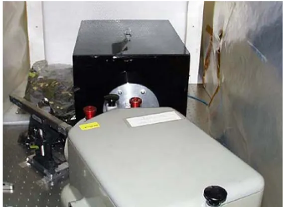
The HI Flight Model A, the first to be assembled is shown with its main elements in figure 1. The structural design and the manufacturing were performed by the University of Birmingham, using carbon-reinforced polymer (CFRP) and honeycomb for maximum lightweighting and temperature stability purposes.
The objective of HI testing is to verify and validate the instrument flight acceptance by demonstrating performance under ambient and simulated mission-level environmental stresses:
- Verify functional and performance under ambient conditions and simulated environments expected to occur during launch preparations, launch, and in-orbit.
- Demonstrate the ability to conduct its science operation without a loss/degradation of data or data interference. - Verify HI instrument mechanical and thermal models. Vibration validates mechanical design model, thermal
vacuum cycles thermal model.
- Verify proper power consumption of the instrument in various operational modes.
- Collect performance data to develop an operations database for calibration purposes, as well as for verifying command/telemetry databases, compiling trending analysis, collecting operating run time, etc.
1. Protoflight vibration
The full instrument has been submitted to protoflight vibrations. The test was performed in the CSL facilities in a class 100 cleanliness level. The protoflight sine and random acceleration levels are summarised hereafter.
Freq [Hz] PSD, G²/Hz Freq [Hz] PSD, G²/Hz 20 0.0031 20 0.0063 80 0.05 80 0.1 800 0.05 800 0.1 2000 0.0032 2000 0.0065 Overall 7.4 Grms Overall 10.4 Grms
Freq [Hz] Acceleration (zero to peak) Freq [Hz] Acceleration (zero to peak)
5 to 7.4 0.5 in (double amplitude) 5 to 6.3 0.5 in (double amplitude)
7.4 to 23 1.4 g 6.3 to 19 1 g
25 to 27 16 g 21 to 23 12 g
29 to 100 1.4 g 25 to 100 1 g
Sweep rate = 4 octave/min Duration 1 minute
Sine Sweep
Thrust Axes (X) Lateral Axes (Y, Z)
Thrust and Transverse Axes (X, Y)
Parallel Perpendicular
Normal to mounting plane (Z)
2. Door deployment under vacuum
A vacuum test in a thermally controlled environment was performed to test the door deployment of the instrument. The HI door was fully deployed in vacuum under cold environment (-25°C on the instrument). This test was followed by an extensive outgassing period, used to release most of the moisture from the composite structure.
3. Thermal vacuum cycles
Using a similar test setup, the instrument has been submitted to thermal cyclings, with survival and operational temperature conditions. During this vacuum sequence, the CCD’s were conductively cooled down to -90°C to maintain a low noise level. Each soak was an opportunity to perform electrical functional tests (images with internal LEDS). Between the thermal soaks, an automatic image acquisition was performed at a cadence identical to the flight operations (20s exposure for HI-1 and 60s exposure for HI-2)
4. Optical alignment check
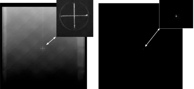
One of the critical parameter on the HI instrument is the co-alignment of the HI-1 and HI-2 optics with the Sun, materialized by the instrument reference cube. An alignment check of these optical axes with the reference cube was therefore one major task of the test campaign. This alignment check was performed between all test sequences (vibration & thermal). In the first case, the optical check was performed with a theodolite focused on the CCD’s while in the second case, the vacuum chamber collimator was used. The next figure shows the images of theodolite beam and collimator seen by HI-1. The centroids of the images were used to compute the optical axis relatively to the instrument reference cube, previously co-aligned with the theodolite / collimator. The accuracy of the measurement only depends on rotation and theodolite accuracy, i.e. a few arcseconds.
Figure 7: Theodolite / collimator images used for alignment check on the HI-1 channel.
The thermal vacuum test did not induce any motivable optical axis deviation. A deviation was detected after the first vibration run but remained stable for the other runs. This initial setting is under analysis.
5. Optical calibration setup
In order to provide a performance evaluation at system level, a set of optical tests has been performed on the full instrument, in simulated flight conditions (pressure and temperature). A collimator (F/10, φ300) was used in the vacuum chamber to provide adequate optical stimuli. The final goal of these measurements is the characterization of the instrument performances in terms of optical throughput and PSF. These data will be processed to calibrate the scientific observations that will be gathered with the instrument.
The measurements were performed with a specific test setup, allowing remote pointing of the instrument in order to scan several angles of observations. Both the instrument and the collimator are connected to a seismic bloc, providing the required stability. The instrument is located on a horizontal fixture mounted on a rotation stage that is used to cover the two optical systems field of views (20 deg for HI-1 and 70 deg for HI-2). The focal plane of the collimator can be provided with a halogen light source (covering HI-1 and HI-2 spectral range) or a high power laser diode (at 670 nm).
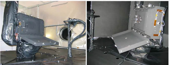
Figure 8: HI FM-A instrument in horizontal configuration for thermal cycling and optical calibration (vacuum chamber is open)
6. In-field analysis
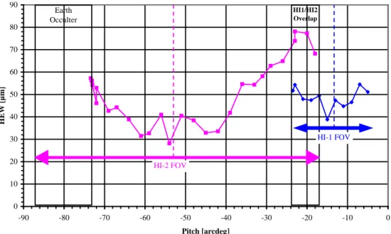
The table 2 summarizes the optical parameters at +20°C. No variation is observed at –30°C. Yaw and roll come from misalignment. Other parameters are within specifications. The figure 9 shows the computed half energy width (HEW) for 1 and HI-2 scan along the pitch axis. The HI-HI-2 field of view is limited on one side by the Earth occulter which intercepts the Earth light on the detector (see also figure 12). On the other side, HI-1 and HI-2 field of view overlaps over 5.3°. This overlap will be used to cross-calibrate in-flight both optical systems. The HEW of HI-1 is in line with the tolerance analysis as well as HI-2 which is slightly better.
HI-1 HI-2 design 13.65 53.36 measured 13.64 53.11 Yaw [°] measured -0.15 -0.02 Roll [°] measured 0.87 -0.02 design 78.40 19.70 measured 77.71 21.44 Pitch [°] Focal length [mm]
Table 2: Optical measurements at 20°C during the calibration.
0 10 20 30 40 50 60 70 80 90 -90 -80 -70 -60 -50 -40 -30 -20 -10 0 Pitch [arcdeg] HEW [µ m ] HI1/HI2 Overlap Earth Occulter HI-2 FOV HI-1 FOV
Figure 9: Measured performances of HI-1 and HI-2 optical systems. 7. Photometric calibration
The photometric calibration is a major parameter in the instrument performances. For such purposes, the collimator has been equipped with a monitoring photodiode measuring directly the collimator beam. The data are still under analysis. 8. Straylight measurements
Front baffle and optics straylight tests have already been performed at sub-system level, but the vacuum sequence was the opportunity to test the straylight at instrument level, including the internal baffle for HI-2. A system test, with all the baffling systems in cascade, requires the detection of extremely faint light level. The measurements conducted in this sequence are mainly verifications that the assembly and the mechanical tests did not introduce any major misalignment leading to important straylight contamination. The instrument environment was blackened as much as possible to limit undesired straylight. For measurements in the direct vincinity of the FOVs, a halogen lamp is used as collimator source in order to avoid damage on the detector. Far from the field of view, a 2W continuous diode laser at 670 nm (into the HI-1 spectral range) is used as collimator source in order to simulate Sun light and Earth light.
The figure 10 shows the straylight acquired at 25° with HI-1. The same artifact can be seen on the symmetric edge of the FOV (i.e. at 1.5°). The origin of straylight is under analysis but a parasitic reflection into the lens barrel is suspected. On the same side, a pattern can be seen coming from the collimator mirror mount not enough baffled. A ghost image can be partly seen on the other side of the detector. The figure 11 shows the straylight spot acquired at 28°. The spot is quasi focalized and shall be carefully studied to look for its origin. Its symmetric at 0° is vignetted by the forward baffle. In both cases, the level of straylight with respect to in-field spot is lower than 5 10-6, compatible with straylight analysis: in the vicinity of the FOVs, a rejection of 10-4 was assumed. Far from the HI-1 field of view, the straylight is not measurable. Concerning the Sun rejection, the most critical parameter for HI-1, the straylight is not measurable, even for long exposure time and is limited by the environment blackening. The rejection of the forward baffle is better than 10-10. This efficiency has already been tested at sub-system level (ref. [2]).
Figure 10: HI-1 image for light source at 25° pitch. Figure 11: HI-1 image for light source at 28° pitch.
The figure 12 shows the straylight acquired at 85° pitch (29° FOV) with HI-2. The focalized spot is on the Earth occulter which can be seen on the figure 12. A diffuse straylight illuminates the detector while a ghost images is set at the other edge of the detector. The straylight is lower than 2 10-7 with respect to in-field spot. This is compatible with the theoretical straylight analysis. The figure 13 shows the straylight acquired far from the field of view (at 120° pitch, 67° FOV) with HI-2. The vane edge of the internal baffle is directly illuminated and diffuses towards the HI-2 entrance. The straylight is lower than 10-8 with respect to in-field spot.
Figure 12: HI-2 image for light source at 85° pitch. Figure 13: HI-2 image for light source at 120° pitch. Earth occulter Ghost image Straylight Collimator mount image Ghost image
(images are enhanced to outline the residual light)
CONCLUSIONS
HI optical systems have been intensively tested at CSL at sub-system level and at system level. At system level, a complete set of environmental tests (vibration, thermal vacuum cycle) has been performed including reference optical tests to check possible degradations. An optical calibration in flight conditions (vacuum and thermal) has been performed. High attention has been taken to design the test setup in order to perform a set of straylight measurements in flight conditions. High rejection levels have been diagnosed even if some discrepancies due to setup straylight have been noticed. They will be improved for the SECCHI HI FM-B model that will be tested similarly after assembly.
ACKNOWLEDGEMENTS
The Heliospheric Imager instruments are developed by Centre Spatial de Liège (B), the Naval Research Laboratory (USA), the University of Birmingham (UK), the Rutherford Appletown Laboratory (UK) and
The Belgian contribution to the STEREO program is funded by the Belgian Federal Science Policy Office (BELSPO), through the Belgium ESA/PRODEX program. The UK contribution is funded by Particle Physics and Astronomy Research Council (PPARC). STEREO/SECCHI is funded under NASA contract S-13631-Y.
REFERENCES
1 R. A Howard, J.D. Moses, D. G. Socker and the SECCHI consortium, "Sun Earth connection coronal and heliospheric investigation"; SPIE 4139, 2000.
2 J.-M. Defise, J.-P. Halain, E. Mazy, P. Rochus, "Straylight tests for the Heliospheric imagers of STEREO", ESA-SP-467, 4th International Symposium on "Environmental Testing for Space Programmes", June 2001.
3 J.M. Defise, J.Ph. Halain, E. Mazy, P. Rochus, R. A. Howard, J. D. Moses, D. G. Socker, G. M. Simnett, D. F. Webb, "Design of the Heliospheric Imager for the STEREO mission" SPIE 4498, 2001.
4 Buffington, A. Jackson, B.V. and Korendyke, C.M., “Wide-angle stray-light reduction for a spaceborne optical hemispherical imager,” Applied Optics, 35, No. 34, pp. 6669-6673, 1996.