HAL Id: hal-02400777
https://hal-mines-albi.archives-ouvertes.fr/hal-02400777
Submitted on 18 Nov 2020
HAL is a multi-disciplinary open access
archive for the deposit and dissemination of
sci-entific research documents, whether they are
pub-lished or not. The documents may come from
teaching and research institutions in France or
abroad, or from public or private research centers.
L’archive ouverte pluridisciplinaire HAL, est
destinée au dépôt et à la diffusion de documents
scientifiques de niveau recherche, publiés ou non,
émanant des établissements d’enseignement et de
recherche français ou étrangers, des laboratoires
publics ou privés.
New model for the prediction of the machining depth
during milling of 3D woven composite using abrasive
waterjet process
Xavier Sourd, Redouane Zitoune, Laurent Crouzeix, Mehdi Salem, M. Charlas
To cite this version:
Xavier Sourd, Redouane Zitoune, Laurent Crouzeix, Mehdi Salem, M. Charlas. New model for the
prediction of the machining depth during milling of 3D woven composite using abrasive waterjet
pro-cess. Composite Structures, Elsevier, 2020, 234, pp.1-12/111760. �10.1016/j.compstruct.2019.111760�.
�hal-02400777�
New model for the prediction of the machining depth during milling of 3D
woven composite using abrasive waterjet process
X. Sourd
a,c, R. Zitoune
a,⁎, L. Crouzeix
a, M. Salem
b, M. Charlas
c aInstitut Clément Ader, CNRS, UMR 5312, 3 Rue Caroline Aigle 31400, Toulouse, FrancebInstitut Clément Ader, CNRS, UMR 5312, Campus Jarlard 81013, Albi, France
cSafran Aircraft Engines, Villaroche, Rond Point René Ravaud, 77550 Moissy Cramayel, France
Keywords: Machining Abrasive water jet 3D woven composite Depth of cut Prediction models
A B S T R A C T
The goal is to study the influence of abrasive water jet (AWJ) machining parameters (jet pressure, traverse speed and scan step) on the cutting depth of 3D woven Carbon Fibres Reinforced Polymer (CFRP) composite. The original material linked to this non-conventional milling process has not been treated yet. The depths of cut were measured and characterized as a function of the machining parameters. Finally, two prediction models for the cutting depth are proposed and validated experimentally.
An increase in cutting depth with the pressure and a decrease as the traverse speed and/or the scan step increase were observed. Thefirst prediction model, based on the pocket depth measurements, has a mean error of 5%. However, the error increases (up to 23%) when the pocket becomes shallow (lesser than 1 mm). The second prediction model, based on the algebraic sum of elementary passes modelled with Gaussian bells, shows atfirst a mean error of 12%. A correction was performed depending on the erosion regime piloted by the depth of the elementary trench constitutive of the pocket. This enhancement, performed thanks to the primary jet diameters measurements with high speed camera, has improved the second model with a mean error of 5% (error < 16%).
1. Introduction
The ongoing ecological revolution imposes strict regulations on the aviation industry to reduce their environmental footprint at a time where air traffic is at its peak. The obvious profitable solution was to reduce the fuel consumption, for which manufacturers addressed the problem by introducing advanced materials having high strength to weight ratio in the aircraft structures. In this context, innovative com-posite materials made of 3D woven fibres and polymer matrix have been developed. This kind of composite material is used for monolithic structures or can be coupled with another material in order to create hybrid structures. In case of use for outer part of the aircraft, these structures are prone to damage during service, such as impact or ero-sion, and for economic reasons composite parts are preferably repaired whenever possible. In fact, the repairing process requires the removal of the damaged area by milling.
In this context, this operation is usually achieved using conventional machining process. However, Fibre Reinforced Polymers (FRPs) are difficult to machine due to numerous aspects of their unique physical properties. Indeed, with a conventional machining process, several
issues are faced, viz. thermal damage of the matrix,fibres and matrix mechanical degradation as well as generation offine particles (dust) which can be harmful for the operators[1,2]. In addition, the thermal and the mechanical defects can be responsible of the reduction of the mechanical performance of the structures in service[1–3]. Apart from the problem related to the mechanical performance, maintaining a constant depth of cut becomes more difficult when the structure is characterized by a complex shape. For these reasons, Abrasive Water Jet (AWJ) machining has been proposed as an alternative solution to the conventional machining process. In fact, this nonconventional process is considered more ecologically and economically efficient, helps to reduce the dispersion of dust and eliminates the thermal da-mage[4,5]. In addition, with this process, it is possible to maintain a constant depth of cut even on slightly curved parts due the minimal dependency of the depth of cut on the standoff distance[6,7]. Several studies[4,7,8]have proven the capability of AWJ to machine a variety of materials, such as titanium alloys and Carbon Fibres Reinforced Polymer (CFRP) composites made of unidirectional plies or 2D woven fabric. However, it seems that no information is available in the lit-erature on 3D woven composite milling with AWJ process.
⁎Corresponding author.
E-mail addresses:xavier.sourd@iut-tlse3.fr(X. Sourd),redouane.zitoune@iut-tlse3.fr(R. Zitoune).
It is important to mention that one of the main concern when mil-ling with AWJ is the presence of large number of machining para-meters, each of them having an influence on the material removal. Indeed, numerous works studied the effect of the main machining parameters, such as waterjet pressure or traverse speed, on the material removal properties of CFRP laminates made of unidirectional plies. In this context, Zitoune et al.[9]performed AWJ milling on a CFRP la-minate (HexPLY M21/35%/268/T700GC) and showed a parabolic evolution of the depth of cut when increasing the abrasiveflow rate (AFR), with an optimum value depending on the water jet pressure and the cutting head’s nozzle diameter. Indeed, when increasing the abra-siveflow rate, more abrasive particles take part in the material removal mechanisms. However, when increasing the number of abrasive parti-cles beyond a certain limit, their mutual interactions increase and they lose the energy provided by the water jet in the process. When per-forming AWJ milling on unidirectional laminates of CFRP (HexPLY T700-M21.A), Hejjaji et al.[7]found that the use of a high water jet pressure leads to a higher milling depth. It has to be highlighted that for all the tested pressures, a traverse speed of around 8 m/min leads to an optimum value of Material Removal Rate (MRR). However, when mil-ling with a high traverse speed, the milled pocket becomes shallower. This result can be explained by the fact that, when machining is con-ducted with high traverse speed, the jet exposition time on the material diminishes. The significant influence of the jet pressure and the traverse speed, hence the kinetic energy of the jet, on the material removal is consistent with the conclusions of numerous studies conducted on metals [10–14]. The analysis and comparison between the several coupons milled during[7]showed that the features related to material removal (depth of cut and MRR) greatly depend on the scan step. In-deed, when the distance between two consecutive trenches increases, the depth of cut is reduced because of a smaller overlapping area, hence a smaller area milled twice. This trend has also been described in sev-eral works concerning metals [15–18], which brought out the im-portance of the degree of overlap in the erosion process.
The choice of the machining parameters is crucial in order to obtain the desired depth of cut but this can be difficult because of their com-plex influence. To solve this issue and ease the choice, many works proposed various methods and models to predict the depth of cut for a given set of machining parameters, mainly for metals but adjustable for other materials. Anwar et al.[16,17]and Lozano Torrubia et al.[19]
developed finite element models in order to describe the footprint generated by AWJ normal milling in Ti-6Al-4V at different jet pressures and traverse speeds, in case of a single trench and single-layered overlapped footprints with variable scan step distances. Though the models give good results (error < 4% for[19]), their main problem is the long computational time (e.g. around 22 h on a 2x8-core 2.6 GHz processor for one simulation [19]), making this predicting method unsuitable from the industrial point of view. Moreover, considering an inhomogeneous material with a specific weaving architecture such as 3D woven CRFP composite would increase the computational time even more. For these reasons, analytical models are more recommended. In this context, Axinte et al.[20], Kong et al.[21]and Billingham et al.
[15]used the same analytical/geometric approach in order to predict the depth of kerfs generated by AWJ milling of titanium. Straight[20]
or variable[21]directions have been considered as well as overlapped trenches [15]. They described the kerf profile thanks to nonlinear
partial differential equations. The influence of a given configuration of parameters (material, pressure, abrasive size andflow rate, etc…) on the material erosion is given by an empirical function called the “etching rate”. The model of[15]accurately predicted the depth of cut from single kerf (error < 4%) to pockets of numerous overlapped trenches with up to three layers (error < 8%). However, the empiri-cally determined etching rate is valid for a given configuration of parameters (material, pressure, abrasive size and flow rate, etc…) which implies that any modification of one or more of these parameters leads to additional tests for a new calibration. Moreover, the model
adaptation for a non-homogeneous material could be difficult. Zitoune et al.[9]and Cénac et al.[22]proposed empirical models in order to determine the optimal abrasive massflow rate (leading to the highest depth of cut for a given set of machining parameters) and the depth of cut for AWJ open pocket milling in aluminium[9,22] and carbon/ epoxy composite laminate made of unidirectional plies [9]. In both studies, authors considered water pressure, orifice diameter, abrasive flow rate and the targeted pocket depth as variable parameters. The traverse speed is an output parameter, which is more in accordance with the needs of manufacturers who have a target depth of cut and want the corresponding machining parameters to achieve it. These prediction models have a good correlation with the experimental measurements (error < 10%) and can be easily calibrated thanks to few tests. Similar models have been developed for titanium AWJ ma-chining[23,24]and the maximum depth of cut as well as the whole trench or pocket profiles have been properly predicted (error < 5% for
[24]). It is important to mention that empirical or analytical models seem to be the most suitable prediction method for an industrial use due to its simple and fast calibration and usage. However, from our knowledge, no such prediction models have been proposed in case of AWJ milling of 3D woven CFRP composite.
The goal of this study is to investigate the ability of the AWJ tech-nology to mill thick 3D woven CFRP composite specimens. In this context, the influence of the parameters of the water jet machining process on the material removal features (depth of cut and material removal rate) are studied. For this, a full factorial experimental design comprising three machining parameters (viz. water jet pressure, tra-verse speed and scan step) has been used for investigation. After the machining phase, the depths of cut have been measured and char-acterized as a function of the machining parameters. Finally, for the prediction of the depth of cut, two models are proposed: thefirst is based on the total pocket depth, the second on the algebraic sum of the elementary passes constitutive of the pocket. The originality of the second model lies in taking into account the regime of erosion piloted by the depth of the elementary trenches constitutive of the pocket.
2. Material and methods
2.1. Material
A plate made of CFRP 3D woven composite was used for the ma-chining tests. Thefibre tows and epoxy resin are respectively referenced as IM7 (Hexcel Composites Company) and PR520 (Cytec Company). The composite plate has been manufactured using the light Resin Transfer Molding (RTM) process. After demoulding, the composite part is characterized by a nominalfibre volume fraction around 54% and an average thickness of 9.75 ± 0.05 mm. The weft and warpfibre yarns are perpendicular to each other. For confidentiality reasons, the me-chanical properties and the weave architecture of the woven composite part are not disclosed. This composite material is owned by Safran Aircraft Engines. From this mother plate, 48 specimens were cut using AWJ, twelve coupons of size 80 mm × 20 mm and thirty-six coupons of size 140 mm × 20 mm in order to machine trenches and pockets with different sets of parameters (cf.Fig. 1) respectively. Three replicates were machined on each specimen. The pocket area was set to 20 mm × 20 mm.
2.2. Abrasive water jet milling machine and parameters
The machining (cut and milling) was performed on an abrasive water jet machine Mach 4c from Flow.Table 1sums up the different fixed and variable parameters used for the experiments. The parameters related to the cutting head geometry shown inTable 1arefixed for economic reasons. The abrasive used is Arabian garnet sand (produced by Garnet Arabia Company Ltd) sized 120 mesh (125 µm in diameter). Due to the existence of a single abrasive feeding system on the AWJ
machine, only one size of abrasive is used during the experiments. The abrasiveflow rate (AFR) was set to 0.18 kg/min which corresponds to the closest value, available with the AWJ machine, to the optimum value to have the maximum depth of cut with the selected cutting head geometry according to Cénac et al.[22]. The standoff distance (SoD)
was fixed at 100 mm because this parameter was found to have no significant influence on the machined depth according to Hejjaji and al.
[7]and Cénac et al.[6]. Moreover, this value has been used and jus-tified by several authors[7,9,25]in case of milling with AWJ.
The choice of the variable parameters is the conclusion drawn from a review concerning milling with AWJ. It was shown that the water jet pressure, the traverse speed and the scan step are the most influent parameters on the pocket’s geometry[7,15,24,26,27]. In this case, four levels of pressure were selected as this parameter was found to be the most influent on the depth of cut[7,24,27]. An almost constant dif-ference has been spotted between the theoretical pressure (Pth) and the
effective one (Peff) during milling. This seems to appear when the water
jet comes out from the focusing tube. For the rest of the study, the effective value of pressure is considered for the analysis of results. Three different levels were studied for both the traverse speed and the scan step.
Full factorial designs were used with different levels of the variable parameters listed inTable 1, with three replicates for each specimen. This corresponds to 36 trenches and 108 pockets milled.
The specimens werefirmly secured with screws on a wooden plank to avoid displacement during milling (cf.Fig. 2a). The pocket milling strategy was the raster scan pattern, keeping the machining direction perpendicular to specimen’s length. In order to avoid speed variations due to the acceleration and deceleration of the cutting head during direction changes, a safety distance was taken on each side of the specimen (cf.Fig. 2b). Thanks to this distance, the traverse speed re-mained stabilised and constant during the machining.
2.3. Characterization methods
2.3.1. Profiles measurement
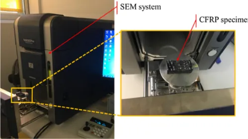
After the machining phase, the profile of all the elementary trenches and pockets were measured thanks to an optical profilometer system referenced under “Infinite Focus SL” from Alicona (cf. Fig. 3). The measurements are performed with a technique called focus variation, acquiring the coordinates of each pixel centre of the scanned area by autofocus along the device’s optical axis. Table 2 gathers the para-meters used for the different measurements. The selected parameters allow a good compromise between acquisition precision (0.2 µm) and measurement time (around 5 min for each pocket). The 2 mm wide scanned strip was split by 1000 planes. Each intersection between a plane and the scanned surface gave its profile and permitted to obtain the mean profile of the trench or pocket.
In order to measure the machined depths, the following procedure was followed. First, the top surface of the specimens was considered as reference. To do so, the scanned surfaces were straightened byfitting a mean square plane trough the top surface. In case of the trenches measurements, the depth is considered as the mean depth value within a range of few microns around the maximum recorded depth. However, for the pockets measurements, the depth is considered as the mean distance between this reference plane and another mean square plane fitting the bottom of the profile. In order to get a clear idea about the repeatability of the machining process (on the depth measurement), for each condition of machining three pockets have been milled and for each pocket two measurements of the depth have been taken. Therefore, the standard deviation has been calculated from these six measurements. In addition to this technique of measurement, the measured profiles have been correlated to the microstructure of the composite material thanks to SEM observations (cf.Fig. 4).
Moreover, topographies of the bottom surfaces of the pocket have been obtained with the optical profilometer by scanning an area of 14 mm × 14 mm at the centre of the machined surfaces at a resolution of 2 µm. A Gaussianfilter with a cut-off of 0.8 mm applied on these topographies has permitted to extract the arithmetical mean height of the bottom pocket surfaces (Sa).
2.3.2. Waterjet measurement
Due to the high standoff distance used for the machining in the present study (100 mm), the jet spreads before hitting the workpiece. In this case, the jet diameter at the exit of the focusing tube can be dif-ferent from the one when it reaches the workpiece. In addition, this variation of jet diameter can be related to the machining parameters. In this context, in order to measure itsfinal diameter, a high speed camera (PHOTRON SA5,filming at 7000 pictures/s) was installed in front of the water jet machine (cf. Fig. 5). The jet was filmed for the four pressure levels.
3. Results and discussion
3.1. Influence of the machining parameters on the trenches and pockets geometry
3.1.1. Trenches
The effects of the jet pressure and the traverse speed on the trench’s depth are presented inFig. 6. The error bars show good repeatability of the machining process with a maximum standard deviation of 60 µm observed when milling with 156 MPa of pressure and 2 m/min of tra-verse speed. It is important to mention that, with this machining con-ditions, the jet kinetic energy transferred to the abrasive particles reaches his maximum value. Moreover, it can be seen that both jet pressure and traverse speed have influence on the milled depth. The increase of pressure leads to a rise of the depth of cut. Indeed, at a traverse speed of 2 m/min, a rise of pressure from 98 to 156 MPa leads to an increase of the pocket depth by 220% (from 0.65 to 1.44 mm). It is
Fig. 1. Side (up) and top (down) views of the specimens used for trench milling.
Table 1
Fixed and variable parameters used during the AWJ machining process. Fixed parameters Variable parameters
Parameter Value Parameter Levels
Focusing tube diameter
1.016 mm Pressure Pth(MPa) 80, 100, 120,
140 Focusing tube length 76 mm Pressure Peff(MPa) 98, 117, 137,
156 Nozzle diameter 0.3302 mm
Type of abrasive Garnet sand Traverse speed V (m/ min)
2, 4, 8 Abrasive size #120
Abrasiveflow rate 0.18 kg/min Scan step SS (mm) 0.5, 1.0, 1.5 Standoff distance 100 mm
explained by the fact that the pressure is linked to the kinetic energy of the jet hence the energy available for the abrasive particles. The more energy they possess, the faster they hit the target surface hence the more material is removed. On the contrary, the pocket depth decreases when increasing the traverse speed, e.g. for a jet pressure of 117 MPa,
the pocket depth is divided by a factor 3.26 (from 0.88 to 0.27 mm) when the traverse speed is multiplied by a factor 4 (from 2 to 8 m/min). As the traverse speed is reduced, the exposure time of the jet on the target surface is higher. This leads to a higher number of particles hitting the surface, hence a greater material removal. These trends (influence of the machining parameters on the depth of cut) are in good agreement with other studies dealing with AWJ milling of composite laminates made of unidirectional laminate[7,9]. However, the values of the machining depth obtained are different from those of the lit-erature[7,9], because the mechanical properties of the CFRP are not the same.
3.1.2. Pockets
Thefirst thing to notice after machining pockets is the jagged pro-files obtained. Indeed, as seen from Fig. 7a, the machined depths fluctuate of about 150 µm around the mean measured value. It means that the measured values of pocket depths are affected by a measure-ment error of around 0.1 mm. The spatial periodicity in the depth variation (around 5 mm from the profile presented inFig. 7a) seems to prove that the weaving architecture of the 3D woven composite mate-rial (presence of resin rich areas) (cf.Fig. 7b) is the cause of the rugged bottom surface of the pocket. It is important to notice that, when ma-chining composite made of unidirectional plies or 2D woven fabric with AWJ, the results are different and a small variation in the machined depth has been observed[7]. Moreover, as seen fromFig. 7a, the pocket profile is also jagged with micro oscillations. This erratic profile is mainly due to the damage generated by the machining process. Indeed, the abrasive water jet produces several kinds of defects and damage, identified by SEM measurements as bare/exposed fibres (cf.Fig. 7c), craters (cf.Fig. 7d) and brokenfibres (longitudinal and traverse fail-ures) (cf.Fig. 7e). These defects have also been observed by Hejjaji et al.[7]when milling CFRP laminates made of unidirectional plies using AWJ process. As shown inFig. 2b, the jet scans are parallel to the weftfibre tows and perpendicular to the warp fibre tows. Hence, the jet removes fibres irrespective of the fibres orientations which can be parallel or perpendicular to the scan direction. In fact, from the SEM picture illustrated inFig. 7c, it can be noticed that there is no influence of the relative angle between the milling direction and thefibre or-ientation on the observed types of defects. These results are in good
Fig. 2. (a) Setup of the machining operations and (b) Schematic top view of the milling path strategy.
Fig. 3. Optical profilometer system used for the milled profiles measurements. Table 2
Parameters used for the profiles acquisition with the optical profilometer.
Parameter Value
Objective 10×
Vertical resolution (µm) 0.2 Lateral resolution (µm) 4.5
agreement with other works[27–29]where authors have shown that, due to the micro-cutting and/or erosion, the signature of the water jet machining process is not affected by the fibres orientation (multi-directional CFRP laminates made of uni(multi-directional plies) with respect to the scan direction. However, with respect to conventional machining, the signature of the process for the same material is influenced by the relative angle between thefibre orientation and the cutting direction
[30].
These defects and damage can impact the pocket surface quality. The evolution of the arithmetical mean height of the bottom pocket surfaces (Sa) in function of the machining parameters (jet pressure and scan step) is presented in theFig. 8. As seen from this figure, Sa is mainly influenced by scan step. Indeed, in case of machining with scan steps superior or equal to 1 mm, the jet pressure has no significant effect on Sa values and an average value around 85 µm is noticed. However, when milling with a scan step of 0.5 mm, Sa increases when the jet pressure increases (from 85 µm to 116 µm for jet pressures of respec-tively 98 MPa and 156 MPa). This result can be explained by the sig-nificant overlap between two consecutive trenches when milling with a low scan step. The already milled material is disintegrated and is more easily removed by the next jet pass, which favours the increase of craters and leads to poor surface quality. This trend has been confirmed by the work of Hocheng et al. [27] when milling CFRP laminate. Moreover, it can be noticed that the Sa values recorded when milling of 3D woven composite are higher compared to the case of AWJ ma-chining of multidirectional laminates made of unidirectional plies (between 6 and 16 µm for the same machining parameters according to
[7]). This difference can be related to the presence of several resin rich zones (cf.Fig. 7b) which are more easily removed than the carbonfibre yarns when 3D woven composite is considered. In addition, it can be mentioned that the traverse speed has not clear influence on Sa.
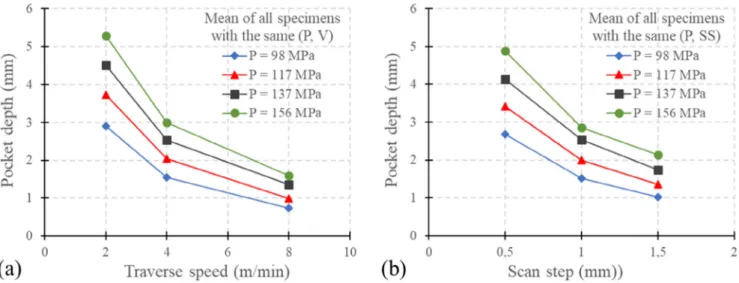
The mean effects of the milling parameters on the pocket depth and on the Material Removal Rate (MRR) are presented inFig. 9andFig. 10
respectively. It can be seen that all the selected process parameters (pressure, traverse speed and scan step) greatly influence the material removal properties. Indeed, the pressure and traverse speed trends of pocket depth follow the same trend as that of trenches (Fig. 9a). This was expected as the trench is the basic entity leading to formation of the pocket by multiple trenches separated from each other by the scan step. The evolution of the pocket depth with respect to the scan step follows the same trend as that of the traverse speed (Fig. 9b). At water jet pressure set to 156 MPa, when the scan step is 3 times higher (from 0.5 to 1.5 mm), the milled pocket is 2.3 times shallower (from 4.89 to
Fig. 4. Scanning Electron Microscope used for the observations of the milled surfaces.
Fig. 5. Experimental setup used for the determination of the jet diameter.
Fig. 6. Effect of the waterjet pressure and the traverse speed on the depth of the milled trench.
2.13 mm). This can be explained as follows. If the scan step is low (e.g. 0.5 mm), each milled trench is mainly overlapped by the next one. The overlapped area is hence milled twice, leading to a greater depth of cut. On the contrary, if the scan step is high (e.g. 1.5 mm), the overlapped area is greatly reduced, generating shallower pockets. Similar trends have been described by Hejjaji et al.[7]when milling CFRP laminates with AWJ.
From the industrial point of view, the material removal rate (MRR) is one of the most interesting parameter for the process optimization. In fact, it can be clearly seen fromFig. 10a that the pressure is a primary parameter influencing the MRR: when it increases from 98 MPa to
156 MPa, the mean MRR varies from 83 mm3/s to 180 mm3/s. This
trend is coherent with other works[7,27]on AWJ milling of CFRP la-minates as well as the observations from the pocket depths in the present study, as the energy available for the abrasive particles is greater when the pressure increases. On the other hand, it appears that the MRR also increases when the traverse speed increases. Nonetheless, it seems that the increase reaches saturation when a traverse speed of 8 m/min is reached, especially for low pressures. This may mean that there is an optimum traverse speed leading to the highest MRR for a given pressure. This conclusion is coherent with the work of Hejjaji et al.[7], which shows an optimum value of traverse speed around 8 m/ min for a maximum MRR at a given pressure in case of AWJ milling of CFRP laminates made of unidirectional plies. It can also be noticed that the evolution of the MRR with respect to the scan step is very inter-esting. Indeed, though choosing a small scan step produces a deep pocket, it does not give the greatest MRR (cf.Fig. 10b). This is probably due to the extra time spend to mill over a large already milled area. Indeed, choosing a scan step of 0.5 mm rather than 1.5 mm leads lo-gically to a milling time 3 times higher. However, as seen fromFig. 9b, the average ratio of depths between 0.5 mm and 1.5 mm of scan step is 2.3. As for the traverse speed, it can be seen that there is an optimum value of scan step around 1 mm giving the maximum MRR, especially in case of low jet pressure. This value corresponds to the jet diameter at the focusing tube exit around 1.016 mm. For higher jet energy (i.e. higher pressure) the jet may spread out, probably because of the high speed which changes theflow from laminar to turbulent at the outer part of the jet, leading to a higher value of jet diameter.
As it was mentioned in the introduction, the choice of the machining parameters is crucial in order to obtain a desired depth of cut. For this reason, two different models are presented for the prediction of the machined depth in function of the process parameters. Thefirst model is similar to the one proposed by several authors [9,22] when
Fig. 7. Example of a machined surface state when machining is conducted with P = 98 MPa, V = 8 m/min, SS = 1.5 mm. (a) Depth measurement from a jagged pocket profile, (b) Optical image of the weaving of the specimens and (c-e) SEM images showing the different types of damage consecutive to AWJ milling with (c) barefibres, (d) craters and (e) broken fibres.
Fig. 8. Mean effect of scan step and pressure on arithmetical mean height of the bottom pocket surfaces Sa.
machining metallic materials or composites made of unidirectional plies. However, this model has been adapted for the 3D woven com-posite. The second model is based on Gauss model mainly used for the prediction of an elementary pass previously used by[23,24,31]when machining isotropic material. Thanks to the measurement of the ef-fective jet diameter, the last model has been adapted and improved for milling 3D woven composite.
3.2. Pocket depth prediction models
3.2.1. Model 1: prediction of the depth of cut using an exponential model As it was clearly observed experimentally, all the three selected parameters (pressure P, traverse speed V and scan step SS) have in flu-ence on the pocket depth H. In order to predict the depth of cut in 3D woven composite, it was proposed to adapt a model used in several studies when machining of metals or composites made of unidirectional plies[9,22]. The model, by considering the influence of the water jet
pressure, the traverse speed and the scan step on the depth of cut, then follows the Eq. (1). The coefficient ‘a’ takes into account the in-homogeneity of the material and can be considered as the machinability of the 3D woven composite used during these experiments.
= ∙ ∙ ∙
H a P V SSb c d (1)
With a, b, c, d: interpolation constants depending on the material and the set of machining conditions 90% of the experimental results were used in order to feed the least mean squares algorithm used for the interpolation constants identification. The remaining specimens were meant for the validation of the model. After the identification phase, the obtained constants are given in the Eq.(2).
= × −∙ ∙ − ∙ −
H 1.29 10 2 P1.285 V 0.875SS 0.786 (2)
This model has a correlation coefficient of 0.9968. The values of the interpolation constants permit to estimate the influence order of the machining parameters as follows, from the most to the least important: pressure, traverse speed and scan step. This is coherent with the ob-servations of other authors concerning AWJ milling on composites made of unidirectional plies or 2D woven fabric[7,9]. In addition, and based on the Eq.(2), it is clear that the power coefficients of the tra-verse speed and the scan step are very similar, respectively−0.875 and −0.786. This similitude is in accordance with the observations from
Fig. 9.
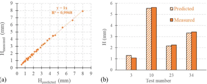
The comparison between the predicted and measured depths is presented in theFig. 11. A clear correlation between the experimental
Fig. 9. Mean effect of the evolution of the pocket depth in function of the machining parameters with (a) influence of the traverse speed for different pressures and (b) influence of the scan step for different pressures.
Fig. 10. Mean effect of the evolution of the MRR in function of the machining parameters with (a) influence of the traverse speed for different pressures and (b) influence of the scan step for different pressures.
and predicted pocket depths can be seen from Fig. 11a. Indeed, the mean relative difference for all the specimens is around 5% with a maximum value of 23% recorded for the shallowest pocket. After a closer look on the predicted depths, it seems than the greatest relative differences with the measured depths are for pockets milled with the highest traverse speed (8 m/min). In these cases, the predicted depth value is mostly overestimated. This can be due to the fact that the constant‘a’ corresponds to the machinability of an equivalent homo-geneous material. Actually, the material removal is greatly dependant on the weaving architecture which describes the local properties. In fact, as the matrix is more easily machined than thefibres, the use of a high traverse speed (i.e. a short exposure time) could leave behind bear strands of fibres without entirely removing them (fibre pull-out phe-nomenon). This could explain the overestimation of the predicted depth compared to the measured one. The pocket depths used for the model validation are also well predicted according toFig. 11b. Indeed, the maximum relative difference is 22% (1.316 mm and 1.080 mm re-spectively for predicted and measured depths) for specimen 3 which have been machined using a traverse speed of 8 m/min. For the other specimens, the relative difference is lower than 5%.
3.2.2. Model 2: prediction of the depth of cut from the Gauss model of elementary pass
The second model developed in this study is based on Gauss model mainly used for the prediction of an elementary pass profile when machining metallic materials [23,24,31]. Based on these works, the general form of the elementary pass can be modelled using the Eq.(3).
= ∙ ⎜⎛ ⎟ ⎝ − ⎞ ⎠ y(x) H e x W 2 2 (3) where H: represents the maximum depth of the elementary pass.
W: corresponds to the width factor of the elementary pass.
As seen fromFig. 6(cf.Section 3.1.1.), the trench’s depth is highly dependent on the pressure and the traverse speed. The maximum depth of an elementary pass has been then modelled by the potential equation
(4).
= ∙ ∙
H(P, V) H P0 HP VHV (4) where H0, HP, HVrepresent the interpolation constants identified
ex-perimentally.
The width factor is defined in the Gauss model as a quarter of the
width at the top of the trench. In this study, the parameter W has been specified so the interval −[ 2W; 2W] contains all the points having a depth greater than a hundredth of the maximum depth. The mean profiles of the milled trenches obtained by the optical profilometer have permitted to measure the trench’s width. The effect of pressure and traverse speed on the trench’s width factor is presented inFig. 12. Each point is the mean measurement value of three replicates. It can be seen that the width factor W increases as the traverse speed decreases: in-deed, when the traverse speed varies from 2 m/min to 8 m/min, the width decreases from 2.2 mm to 1.6 mm. However, the pressure seems to have no significant influence on the trench’s width factor. It can be noticed that the width factor W is slightly lower in case of milling with a traverse speed of 8 m/min and a pressure of 156 MPa than the other elementary passes milled with the same traverse speed. However, the standard deviation is high enough to consider that the value is within the tolerance interval. The independence of the width factor on the pressure has also been proven in case of titanium AWJ milling[24]. The width factor W is then modelled by the potential Eq.(5).
= ∙
W(V) W V0 WV (5)
where W0and WVrepresent the interpolation constants identified
ex-perimentally.
The interpolation constants from the Eqs.(4) and (5)are determined thanks to the least mean squares algorithm fed by the experimental
Fig. 11. Results of the prediction model of pocket depth: (a) predicted values with respect to measured ones and (b) validation of the model with the remaining specimens.
Fig. 12. Influence of the waterjet pressure and the traverse speed on the width of the milled trench.
measurements from the trenches profiles and gathered inTable 3. The predicted values of the trench depth and the width factor given by the Eqs.(4) and (5)are very close to the experimental measurements with correlation coefficients of respectively 0.993 and 0.980. In fact, the mean error of the predicted depths is less than 10%. However, when milling is conducted with the lowest pressure (e.g. 98 MPa) and the highest traverse speed (e.g. 8 m/min), the model(4)overestimates the depth and the error reaches its maximum and is around 46%. This overestimation of the depth might be due to the high standard deviation of the depths over the three replicates which is probably influenced by the local variability of the mechanical properties of the composite materials as well as the complex architecture of the 3D weaving. In-deed, the standard deviation in this configuration (0.044 mm) is around 31% of the mean depth (0.143 mm). As a matter of comparison, the standard deviation for the other sets of parameters corresponds to maximum 12% of the mean depth. The mean error of the width factor prediction is 2.5% with a maximum error of 7.4%.
As the jet path strategy considered in this study is a raster scan pattern (cf.Fig. 2), the pocket profile Y(x) corresponds to the sum of n elementary passes separated from each other by the scan step SS fol-lowing the Eq.(6).
∑
= ⎛ ⎝ ⎜ ⎜ ∙ ⎞ ⎠ ⎟ ⎟ ⎜ ⎟ = ⎛ ⎝ − − × ⎞ ⎠ Y(x) H(P, V) e i 1 n (x i SS) W(V) 2 2 (6) In order to have the maximum depth of the pocket, some simplifi-cation of the model is performed. As the pocket profile is equal to the sum n elementary trenches, it can be considered that the area of the pocket section is equal to the section area of n elementary passes se-parated by the scan step SS. Bui et al.[24]proposed this simplificationin case of AWJ milling of titanium and obtained the Eq.(7).
= π∙ ∙
Y H W
SS
max
(7) By merging this equation with the potential models(4) and (5), the pocket depth can be predicted thanks to the Eq.(8).
= × −∙ ∙ − ∙ −
Ymax 1.05 10 3P1.839 V0.988 SS 1 (8)
Before going further, it has to be noticed that the power of the traverses speed is close to−1 which means that the pocket depth is inversely proportional to the traverse speed. This is in accordance with the conclusion of several studies[7,24,27,31]concerning the influence
of the traverse speed on the pocket depth. Moreover, both scan step and traverse speed have the same influence on the pocket depth. It is in coherence with the similar trends shown inFig. 9.
Although the proposed model has a correlation coefficient of 0.9891, the mean error for all the specimens is around 12% with a maximum value of 46% recorded for the deepest pocket. It is important to mention that the greatest relative differences with the measured depths concern the pockets which are characterized by elementary passes with high depth. In these cases, the predicted pocket depth is overestimated. This appears that there are two different regimes of erosion depending on the depth of the elementary pass. Indeed, these two modes have been described by Billingham et al.[15]during the modelling of the overlapped trenches. In case of overlapping a shallow trench, the jet hits an almost surface and there is no significant varia-tion of particles impingement through the jet diameter. On the con-trary, in case of overlapping a deep trench, the difference in particles impingement between the already milled surface and the unmilled one
leads to a reduced material removal. According to the authors of[15], this non-linearity diminishes as the scan step increases until having a distance between two consecutive trenches equal to the jet diameter. Because of the high standoff distance used for the machining in the present study (100 mm), the jet spreads before hitting the workpiece. As seen fromFig. 13, presenting pictures of the jet taken with high speed camera and post-treated with MATLAB software, this spreading generates two zones within the water jet respectively called primary and secondary jets. By having a closer look on bothFig. 13a and b, it can be observed that though the diameter of the secondary jet seems to remain stable when increasing the water jet pressure, the primary jet diameters tends to increase. Further measurements have been per-formed and the results, plotted inFig. 14, confirm this assumption.
Though the secondary jet diameter is almost independent of the pres-sure with a mean value of 6.90 mm, the primary jet diameter, on the contrary, increases with the pressure. Indeed, when pressure increases
Table 3
Interpolation constants for the Eqs.(4) and (5).
H0 HP HV W0 WV
2.265e−4 1.839 −0.775 2.616 −0.213
Fig. 13. Pictures from the high speed camera of the water jet [(a) P = 98 MPa, (b) P = 156 MPa].
Fig. 14. Influence of the pressure on the primary and secondary jet diameters close to the workpiece.
from 98 to 156 MPa, the jet diameter spreads from 1.54 to 2.42 mm. In order to take into account the regime of erosion in the pocket depth prediction, an error parameter ‘e’ has to be introduced in the model. According to Billingham et al.[15], the change in erosion re-gime occurs when the elementary pass depth reaches a certain threshold value, considered in this study as the primary jet radius rpj.
However, it seems that the scan step has an influence on both erosion regimes as shown fromFig. 15. Indeed, though the error can be con-sidered as proportional to the depth of an elementary trench‘h’ con-stituting the pocket, it is also highly dependent on the scan step (for h = 1.44 mm, 13% and 46% when the scan step is respectively 1.5 mm and 0.5 mm). Moreover, the influence of h is reduced as the scan step comes closer to the primary jet diameter, the slopes of the curves being almost identical for scan steps of 0.5 mm and 1 mm and diminishing for a scan step of 1.5 mm.
The Eq.(8)then becomes:
= − ∙ × −∙ ∙ − ∙ − Ymax (1 e) 1.09 10 3 P1.834 V 0.983SS 1 (9) With = ∙ − ≤ e E10 (2rpj SS)E11 if h rpj = ∙ − > e E20 (2rpj SS)E21 if h rpj
where E10, E11, E20and E21are interpolation constants experimentally
determined.
The interpolation constants from the Eq.(9), gathered inTable 4, are determined thanks to a least mean squares algorithm fed by the experimental measurements from the trenches profiles.
Thanks to this correction, the model(9)has a correlation coefficient of 0.9989. The mean error for all the specimens is now 5.3% with a maximum value of 16.1%. It has to be noticed that only three predicted values have an error greater than 10% againstfifteen before the cor-rection. As seen fromFig. 16, the correction has been mostly applied on the deepest pockets.
Though the Eqs.(2) and (8)are very similar, the major difference
lies in the method of deriving the coefficients in the models. Indeed, to derive the Eq.(2), milling of a complete pocket is required. However, for the model of Eq.(8), a single trench is enough to obtain the required interpolation constants. This will reduce the time necessary for the machining tests needed for the prediction of the model. Moreover, the Eq. (8)considers the shape of elementary passes constitutive of the
milled pocket for the prediction. It permits to take into account the influence of the erosion mode on the effective pocket depth, hence the correction proposed afterward (Eq.(9)). On the contrary, the Eq.(2)
can be considered as a macroscopic prediction model which does not take into consideration the phenomena of interaction of the jet with previously formed trench on the pocket depth.
As for the other prediction model presented inSection 3.2.1., the material is considered as a homogeneous equivalent of the real one. Of course, thefibres and the matrix have very different wear behaviour which can explain the remaining errors of prediction.
4. Conclusion
In this study, an experimental and numerical study of AWJ milling of 3D woven CFRP is presented. Firstly, from the full factorial experi-mental designs, the influence of machining parameters (viz. the water jet pressure, the traverse speed and the scan step) on the material re-moval properties (depth of cut and MRR) has been investigated. This experimental study has led to propose two analytical models for the prediction of the depth of cut in function of the machining parameters. Thefirst model is based on the pocket depth measurements (Model 1), the second model is resulting from the algebraic sum of elementary passes (Model 2). Thanks to the in situ instrumentation of the water jet by high speed camera, the predicted values obtained by the second model have been improved. The additional measurements have per-mitted to correct the model with the introduction of the erosion mode piloted by the effective diameter of the primary jet. Based on the ex-perimental and analytical investigation, the following conclusions can be drawn:
•
The depth of cut is influenced by the pressure, the traverse speed and the scan step in order of importance. Indeed, it was clearly shown that the increase in jet pressure favours the augmentation of the depth of cut. However, the depth of cut decreases with the augmentation of the traverse speed and the scan step. From this point of view, 3D woven CFRP composite reacts to the main AWJ milling parameters the same way the CFRP laminates do. However, contrary to surfaces of composite made of unidirectional plies gen-erated by AWJ machining, the AWJ milled surfaces of 3D woven composite are characterized by important macro and microFig. 15. Influence of the elementary pass depth and the scan step on the relative error of prediction.
Table 4
Interpolation constants for the Eq.(9).
E10 E11 E20 E21
0.1376 1.2832 0.0506 2.3017
Fig. 16. Results of the prediction model of pocket depth before and after the correction.
waviness. The macro undulations can be explained by the 3D weaving architecture as well as the rich areas of resin due to mesh size of 5 mm. The micro undulations are originating from the defects generated by the machining process itself. Indeed, bare and broken fibres as well as craters of few tens of microns in size have been observed on the bottom surface of the milled pockets.
•
The MRR is strongly influenced by the jet pressure and the experi-mental analysis has shown that there are critical values of traverse speed and scan step, respectively 8 m/min and 1 mm, which max-imize the material removal rate. In addition, the critical value of scan step corresponds to the focusing tube exit diameter.•
The prediction model of depth of cut resulting from the pocket depth measurements (Model 1) is in good agreement with the experi-mental values (correlation coefficient of 0.9986). With this model, the mean relative error recorded is around 5%. However, it seems to be less efficient in case of milling shallow pockets where the max-imum error reaches 23%.•
The prediction model of depth of cut based on the elementary passes depth measurements (Model 2) allowed to identify two regimes of erosion. These regimes of erosion strongly depend on the depth of the elementary passes constituting the pocket. However, both ero-sion regimes have phenomena making thefinal pocket profile dif-ferent from the algebraic sum of elementary passes. The threshold between the two regimes has been set as the primary jet radius close to the workpiece. For trench depths below this value, the influence of the scan step is greatly reduced. A correction has then been proposed on the Model 2 by taking into account the change in erosion regime as the elementary passes become deeper. In this context, measurements of the effective jet diameter thanks to high speed camera have shown that the primary jet spreads when the pressure increases. These additional data have been introduced within the correction of the model. Thanks to this improvement, the prediction values of the depth of cut in function of the machining parameters are in good agreement with the experimental values (correlation coefficient of 0.9989). In fact, the mean error between the predicted values and those measured is around 5% with a maximum error of 16%. Moreover, it has to be noticed that the number of specimens for which prediction value has an error greater than 10% is greatly reduced compared to Model 1. Hence, only four specimens, against 15 for thefirst model, have an error greater than 10%. This proves that the distinction between the two erosion modes in the model significantly improves its efficiency.•
The use of a high speed camera has permitted to identify two zones within the jet. Though the size of the secondary jet (i.e. external zone) remains stable as the jet pressure increases, the primary jet (i.e. core zone) spreads when using a higher pressure. Indeed, an increase of around 30% of the primary jet diameter has been re-corded between the two extreme values of pressure used in this study. The originality of the second prediction model (Model 2) lies within the consideration of this phenomenon and its link with the change of erosion mode. Indeed, to the authors knowledge, no such phenomenon has been considered before in the literature for a prediction model of depth of cut consecutive to AWJ milling of 3D woven composite.Declaration of Competing Interest
The authors declare that they have no known competingfinancial interests or personal relationships that could have appeared to influ-ence the work reported in this paper.
Acknowledgments
The collaboration with Safran Aircraft Engines is gratefully ac-knowledged.
References
[1] Nguyen-Dinh N, Zitoune R, Bouvet C, Leroux S. Surface integrity while trimming of composite structures: X-ray tomography analysis. Compos Struct 2019;210:735–46. [2] Haddad M, Zitoune R, Eyma F, Castanié B. Study of the surface defects and dust
generated during trimming of CFRP: Influence of tool geometry, machining para-meters and cutting speed range. Compos Part A Appl Sci Manuf 2014;66:142–54. [3] Haddad M, Zitoune R, Eyma F, Castanié B. Influence of machining process and
machining induced surface roughness on mechanical properties of continuousfiber composites. Exp Mech 2014;55:519–28.
[4] Hashish M. An investigation of milling with abrasive-waterjets. J Eng Ind 1989;111:158.
[5] Ramulu M, Kunaporn S, Arola D, Hashish M, Hopkins J. Waterjet machining and peening of metals. Analyzer 2000;122:90–5.
[6] Cénac F, Collombet F, Zitoune R, Déléris M. Abrasive-water-jet blind-machining of polymer matrix composite materials. ECCM 2008.
[7] Hejjaji A, Zitoune R, Crouzeix L, Le Roux S, Collombet F. Surface and machining induced damage characterization of abrasive water jet milled carbon/epoxy com-posite specimens and their impact on tensile behavior. Wear
2017;376–377:1356–64.
[8] Arola D, Ramulu M. Material removal in abrasive waterjet machining of metals– surface integrity and texture. Wear 1997;210:50–8.
[9] Zitoune R, Collombet F, Cénac F. Méthodologie spécifique à l’usinage des compo-sites par jet d’eau abrasif. Tech l’ingénieur 2013.
[10] Chillman A, Ramulu M, Hashish M. Waterjet peening and surface preparation at 600 MPa: a preliminary experimental study. J Fluids Eng 2007;129:485–90. [11] Chillman A, Ramulu M, Hashish M, Cantrell A. High pressure waterjets– an
in-novative means of alpha case removal for superplastically formed titanium alloys. Key Eng Mater 2010;433:103–11.
[12] Chillman A, Ramulu M, Hashish M. Waterjet and water-air jet surface processing of a titanium alloy: a parametric evaluation. J Manuf Sci Eng 2010;132(011012):1–10. [13] Gupta TVK, Ramkumar J, Tandon P, Vyas NS. Role of Process Parameters on Pocket
Milling with Abrasive Water Jet Machining Technique 2013;7:348–53. [14] Azhari A, Schindler C, Kerscher E, Grad P. Improving surface hardness of austenitic
stainless steel using waterjet peening process. Int J Adv Manuf Technol 2012;63:1035–46.
[15] Billingham J, Miron CB, Axinte DA, Kong MC. Mathematical modelling of abrasive waterjet footprints for arbitrarily moving jets: part II– overlapped single and multiple straight paths. Int J Mach Tools Manuf 2013;68:30–9.
[16] Anwar S, Axinte DA, Becker AA. Finite element modelling of abrasive waterjet milled footprints. J Mater Process Technol 2013;213:180–93.
[17] Anwar S, Axinte DA, Becker AA. Finite element modelling of overlapping abrasive waterjet milled footprints. Wear 2013;303:426–36.
[18] Alberdi A, Rivero A, Lopez De Lacalle LN. Experimental study of the slot over-lapping and tool path variation effect in abrasive waterjet milling. J Manuf Sci Eng 2011;133. 034502-1-034502-4.
[19] Lozano Torrubia P, Axinte DA, Billingham J. Stochastic modelling of abrasive wa-terjet footprints usingfinite element analysis. Int J Mach Tools Manuf
2015;95:39–51.
[20] Axinte DA, Srinivasu DS, Billingham J, Cooper M. Geometrical modelling of abra-sive waterjet footprints: a study for 90° jet impact angle. CIRP Ann - Manuf Technol 2010;59:341–6.
[21] Kong MC, Anwar S, Billingham J, Axinte DA. Mathematical modelling of abrasive waterjet footprints for arbitrarily moving jets: part I - single straight paths. Int J Mach Tools Manuf 2012;53:58–68.
[22] Cénac F, Zitoune R, Collombet F, Deleris M. Abrasive water-jet milling of aeronautic aluminum 2024–T3. Proc Inst Mech Eng Part L J Mater Des Appl 2013. [23] Sultan T, Gilles P, Cohen G, Cénac F, Rubio W. Modeling incision profile in AWJM
of Titanium alloys Ti6Al4V. Mech Ind 2016;17:403.
[24] Bui VH, Gilles P, Sultan T, Cohen G, Rubio W. A new cutting depth model with rapid calibration in abrasive water jet machining of titanium alloy. Int J Adv Manuf Technol 2017;93:1499–512.
[25] Cénac F, Collombet F, Zitoune R, Déléris M. Usinage des Composites par Jet d’eau Abrasif. JNC17, 2011.
investigations on pocket milling of Titanium alloy using abrasive water jet ma-chining. FME Trans 2016;44:133–8.
[27] Hocheng H, Tsai HY, Shiue JJ, Wang B. Feasibility study of abrasive-waterjet mil-ling offiber-reinforced plastics. J Manuf Sci Eng 1997;119:133–42.
[28] Saleem M, Toubal L, Zitoune R, Bougherara H. Investigating the effect of machining processes on the mechanical behavior of composite plates with circular holes. Compos Part A Appl Sci Manuf 2013;55:169–77.
[29] Hejjaji A, Zitoune R, Toubal L, Crouzeix L, Collombet F. Influence of controlled
depth abrasive water jet milling on the fatigue behavior of carbon/epoxy compo-sites. Compos Part A Appl Sci Manuf 2019;121:397–410.
[30] Cadorin N, Zitoune R. Wear signature on hole defects as a function of cutting tool material for drilling 3D interlock composite. Wear 2015;332:742–51.
[31] Alberdi A, Rivero A, Lopez De Lacalle LN, Etxeberria I, Suárez A. Effect of process parameter on the kerf geometry in abrasive water jet milling. Int J Adv Manuf Technol 2010;51:467–80.


![Fig. 13. Pictures from the high speed camera of the water jet [(a) P = 98 MPa, (b) P = 156 MPa].](https://thumb-eu.123doks.com/thumbv2/123doknet/12271816.321704/10.892.468.818.79.481/fig-pictures-high-speed-camera-water-mpa-mpa.webp)

