HAL Id: hal-00750613
https://hal.inria.fr/hal-00750613
Submitted on 11 Nov 2012
HAL is a multi-disciplinary open access
archive for the deposit and dissemination of
sci-entific research documents, whether they are
pub-lished or not. The documents may come from
teaching and research institutions in France or
abroad, or from public or private research centers.
L’archive ouverte pluridisciplinaire HAL, est
destinée au dépôt et à la diffusion de documents
scientifiques de niveau recherche, publiés ou non,
émanant des établissements d’enseignement et de
recherche français ou étrangers, des laboratoires
publics ou privés.
”FlyVIZ”: A Novel Display Device to Provide Humans
with 360o Vision by Coupling Catadioptric Camera with
HMD.
Jérôme Ardouin, Anatole Lécuyer, Maud Marchal, Clément Riant, Eric
Marchand
To cite this version:
Jérôme Ardouin, Anatole Lécuyer, Maud Marchal, Clément Riant, Eric Marchand. ”FlyVIZ”: A
Novel Display Device to Provide Humans with 360o Vision by Coupling Catadioptric Camera with
HMD.. ACM Symp. on Virtual Reality Software and Technology, VRST’12, 2012, Toronto, Canada.
�hal-00750613�
“FlyVIZ”: A Novel Display Device to Provide Humans with
360° Vision by Coupling Catadioptric Camera with HMD
Jérôme Ardouin
1ESIEA - INSA - Inria
Anatole Lécuyer
2Inria
Maud Marchal
2INSA - IRISA - Inria
Clément Riant
3ESIEA
Eric Marchand
2IRISA - Inria
ABSTRACT
Have you ever dreamed of having eyes in the back of your head? In this paper we present a novel display device called FlyVIZ which enables humans to experience a real-time 360° vision of their surroundings for the first time. To do so, we combine a panoramic image acquisition system (positioned on top of the user’s head) with a Head-Mounted Display (HMD). The omnidirectional images are transformed to fit the characteristics of HMD screens. As a result, the user can see his/her surroundings, in real-time, with 360° images mapped into the HMD field-of-view. We foresee potential applications in different fields where augmented human capacity (an extended field-of-view) could benefit, such as surveillance, security, or entertainment. FlyVIZ could also be used in novel perception and neuroscience studies.
Categories and Subject Descriptors
B.4.2 [Input/Output and Data Communications]: Input/Output Devices. -Image display: I.4.1 [Image Processing and Computer Vision]: Digitization and Image Capture. -Imaging geometry.
General Terms
Design
Keywords
Display device; 360° vision; catadioptric camera; panoramic images; Head Mounted Display
1. INTRODUCTION
People are familiar with sophisticated optical devices and can use them to adapt their vision to various uses. For instance, microscopes and telescopes are classical optical devices that can magnify small or distant objects. These devices map a small part of the Field of View (FoV) to a larger one. Such mapping process decreases the effective FoV of the user.
The human field of view is limited to 180 degrees horizontally and 110 degrees vertically. Increasing the natural FoV is actually very difficult to achieve with traditional optical devices. In this paper, we introduce a display device which can enhance the human FoV, and enable a 360° horizontal FoV (80° vertically with our system). This novel device (see Figure 1), called FlyVIZ, is based on three components: (1) an acquisition system (e.g., a catadioptric sensor, on top of the user’s head, for capturing 360° images), (2) a Head-Mounted Display (HMD) to display the processed image to the end-user in real-time, and (3) a computer vision algorithm to map the captured 360° images to the shape and dimensions of HMD screen).
In the remainder of this paper we first review related work. Second, we describe the global concept of FlyVIZ and its main components. Then, we present a proof-of-concept prototype and detail the proposed hardware and the real-time image processing algorithm. Finally, we discuss the performances and potential uses of our novel approach.
2. RELATED WORK
A HMD is a display device, worn on the head or as part of a helmet, which has a small display in front of one (monocular HMD) or both eyes (binocular HMD). The typical horizontal FoV of research or commercial HMDs ranges from 24° to 187°. Efforts are regularly made to extend the FoV of HMDs. As an example, Sensic company notably proposed an approach based on a mosaic of small screens [1], that are able to extend the FoV while maintaining good resolution at the same time. The field of view of an HMD is also a critical parameter from a human perception perspective. When a 1:1 scale is used with a limited FoV, HMD users tend to complain, and often feel like they are looking through a keyhole.
The combination of HMDs with panoramic cameras has been scarcely studied up to now. Few examples exist in the tele-operation field. In [2], Nagahara et al. coupled a panoramic imaging sensor with a wide-FoV HMD for the purpose of remote exploration/visualization. The HMD was coupled with a head tracker, so that the user could explore the remote 360° FoV by turning his/her head. The image displayed in the HMD was not a panoramic image and the remote 360° FoV was sequentially explored. A similar system can be found in [3] for visual surveillance and remote monitoring. In Virtual Reality
Permission to make digital or hard copies of all or part of this work for personal or classroom use is granted without fee provided that copies are not made or distributed for profit or commercial advantage and that copies bear this notice and the full citation on the first page. To copy otherwise, or republish, to post on servers or to redistribute to lists, requires prior specific permission and/or a fee.
VRST’12, December 10–12, 2012, Toronto, Ontario, Canada. Copyright 2012 ACM 978-1-4503-1469-5/12/12...$15.00.
1 ardouin@esiea-ouest.fr
2{alecuyer, mmarchal, marchand}@irisa.fr 3 riant@et.esiea-ouest.fr
Helmet HMD Catadioptric
sensor
applications, a similar process of exploration of the virtual world is adopted [4]. The virtual 360° FoV is explored sequentially thanks to a head tracker (ie. a device able to capture the user head orientation) and turning head movements. Interestingly enough, Fiala and Roth demonstrated the benefit of using a remote panoramic imaging system for tele-operation [5]. In particular, it removes the need for a closed-loop feedback for the remote low-FoV camera, and then reduces the overall latency.
The distortion or extension of human vision has been investigated in several scientific fields such as Neuroscience (e.g., for studying visual perception and brain adaptation using prisms [6]), or Augmented Reality (e.g. by superimposing artificial information onto the naturally perceived images [7]). In the artistic domain, some performers have also developed systems that can extend human vision. In his 3RDI project, the artist Wafaa Bilal, was equipped with a camera on the back of his head giving a reversed point of view of his everyday life and displaying images to the audience [8]. The Crew Company coupled a panoramic sensor with an HMD and a head tracker. They could set up different performances in which the user could explore part of remote or recorded panoramic videos (similarly to the tele-operation systems aforementioned). Finally a similar artistic experience was built to play with the feeling of “presence” of the users [9].
To the best of the authors' knowledge, no previous work proposed a display to experience full 360° vision of one's surroundings in real-time.
3. THE “FlyVIZ” CONCEPT
With FlyVIZ, our objective is to enhance the natural human field of view. We intend to reach a full 360° FoV of the user’s surroundings, in real-time. This would fulfill a dream of humans: to be able to “see behind their back” or see like some animals, such as flies, with a wider FoV, even reaching a fully panoramic vision. This objective is obviously difficult to achieve using simple and traditional optical devices. However, an image processing approach connecting an image acquisition system with a head-mounted display could suit our purpose. As illustrated in Figure 2, three main functions should drive the design of such a system. First it has to capture omnidirectional information/images from the user’s environment (image acquisition). Second, it has to transform this view into a meaningful representation (image transformation). Finally, it has to display this view to the user (image presentation). The Image acquisition can be done with a catadioptric sensor, i.e., the combination of a camera with a mirror. Various shapes of mirrors could be used such as parabolic, hyperbolic, or spherical mirrors. Composite sensors could also be used, i.e., a set of multiple cameras assembled in a circle or sphere to cover the 360° FoV. The Image transformation requires a
processing unit to carry out the necessary computations. This can be a laptop, a netbook, a wearable computer or dedicated hardware (ASIC). Smartphones with enough processing power could also fit. The Image presentation can be made using a Head-Mounted Display, but specific video glasses could also be suitable. As a complementary requirement, the whole system must preferably be wearable and compatible with the user’s locomotion.
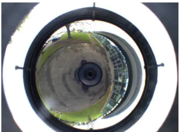
Proof of concept: In this paper, we describe a first prototype of the FlyVIZ concept that is displayed in Figure 1. The image acquisition step is achieved with a catadioptric sensor [10] made up of a hyperbolic mirror and a traditional 6mm-lens mounted on a CCD camera (IDS µEye 2210). The image acquisition system is mechanically attached on a helmet. Figure 3 displays a typical image acquired by this system. The panoramic images are acquired in the head reference frame (and so, it does not require head tracking). The image transformation is done on a laptop computer worn by the user in a backpack. The image presentation is done by means of a HMD (SONY HMZ-T1).
4. PROCESSING OF 360° IMAGES
In this section we further detail the image transformation process that is a key component of our system. The purpose of the image transformation algorithm is to transform the acquired image (Figure 3) into an image that can be displayed in the HMD. A comprehensible representation of the environment is targeted, i.e., a projection which can be effectively perceived by the user. With our approach, each pixel displayed in the HMD has to be mapped to its corresponding location in the acquired image. The image transformation is achieved in two successive steps, which correspond to two different projections:
1. Projection between a location on the final displayed image and a direction of the space ;
2. Projection between a direction of the space and its respective location in the acquired image.
For the first projection, the mathematical formulation of the problem consists in mapping all the space directions onto a plane. Mapping one direction of the 3D space is equivalent to map a point from a unit sphere onto a plane [10]. This mapping problem (and its inverse problem) has been widely studied by mathematicians and cartographers [11]. We use the plate carrée cylindrical projection [11] (aka. the equirectangular projection) that is widely used both in cartography and panoramic imaging. Although the plate carrée projection generates some distortions at poles, it preserves the shapes along the 0° parallel. This is known
Figure 3: image provided by the Catadioptric system.
Image Acquisition Image Transformation Image Presentation
to strongly help the overall human interpretation of the final view. The second projection corresponds to the calibration of our optical system. The equations map a 3D space vector to its corresponding location in the acquired image. Details on the modeling and the calibration of catadioptric sensors can be found in [10] and [12]. A practical implementation can also be found in [12]. In our setup we use a dedicated sensor calibration algorithm available in the OCamCalib toolbox [12]. The procedure takes about 15 minutes, and does not require to be fulfilled again, as soon as the optical alignment of the camera lens and the mirror is preserved. The calibration parameters are then stored and can be used later, at runtime.
Mathematically, the whole process can be described as follows:
→
→
→
'
'
y
x
Z
Y
X
y
x
P S Mϕ
λ
Thus, in the first step of our image transformation algorithm, a pixel with coordinates (x,y) is transformed to (λ,φ) with the plate carrée inverse projection (P) which is a simple affine transformation that remaps the x coordinates to [-π,π] and y to [-π/2,π/2]. Then, the 3D space vector (X,Y,Z) is deduced from the parameterized form of the sphere equation (S).
= ) sin( ) sin( ) cos( ) cos( ) cos(
ϕ
λ
ϕ
λ
ϕ
Z Y XFinally, the associated coordinates in the input image (X’,Y’), are computed from (X,Y,Z), using the camera model (M) [12]. At runtime, each raw image is acquired from the catadioptric sensor and uploaded into the video memory as a texture buffer. A full-screen quad is then rasterized by using a dedicated fragment program on GPU. To transform the raw image into the final unwrapped image, the fragment program has to handle the two mappings described earlier: the plate carrée projection and the catadioptric camera model. For each processed pixel in the final image, (λ,φ) coordinates are deduced from UV coordinates of the full screen quad. The corresponding 3D vector is computed using the inverse mapping of the plate carrée projection. This vector is then used to address the input image according the catadioptric camera model [12]. This texture look up is done using hardware texture linear filtering to maintain smoothness over the final image. Both the raw panoramic image addressing and the plate carrée cylindrical projection are implemented at a fragment level. Such an implementation thus benefits from the parallel processing power available in modern GPUs and optimizes computation performances.
5. SYSTEM PERFORMANCES
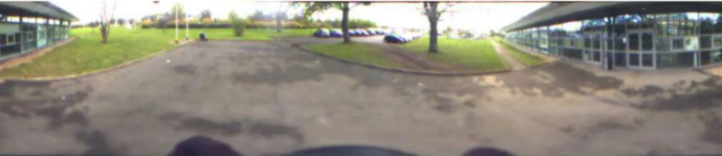
Our prototype is based on an HMD with a FoV of 45° and a 16:9 aspect ratio (ref. SONY HMZ-T1). This aspect ratio fits relatively well with the properties of the plate carrée projection that constrains the displayed image to an aspect ratio of 2:1. Taking our optical setup into account, the final image is displayed in the HMD with 360° horizontal FoV and 80° vertical FoV (Figure 4). Our image transformation algorithm is implemented in C++ using OpenGL API and the GLSL shading language. We have benchmarked our algorithm on two different platforms with both a high (laptop) and low computational performances (netbook). The resulting frame rates obtained in HMD are given in Table 1. With a high-end laptop, the frame rate is far above the refresh rate of the camera (60Hz). But even with a low-cost netbook, the refresh rate meets a real-time constraint (24Hz). The overall latency of the system (end to end from acquisition to display) has been measured by taking pictures of a precision clock and its image processed by the system and displayed in the HMD. The value seen through the HMD was then subtracted to the directly observed value. With this procedure, we found an average latency of 83 ms.
Table 1: Computation performance (frame rates) Hardware CPU GPU Frame Rate (Hz)
15’ laptop i7-2820QM 2.30GHz Quadro 2000M 480 12’ netbook ATOM D525 1.8GHz ION2 24
6. SYSTEM IN USE
The FlyViz system is fully operational and has been tested by multiple users and in different conditions (e.g., indoor or outdoor). We can use different illustrative scenarios as illustrated in Figures 5 and 6.
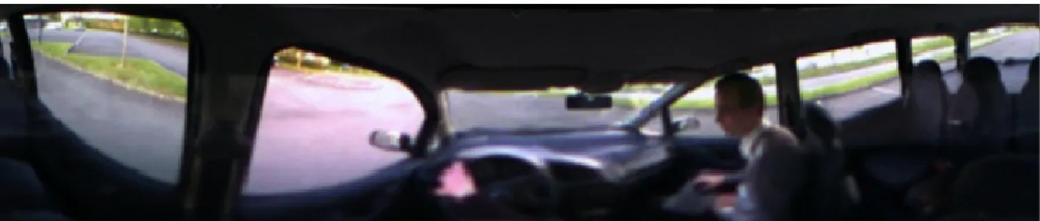
During these tests, users get used within the first 15 minutes of practice, letting them to smoothly move in their environment. Users also get used to the new visual feedback loop of their arms and hands, letting them open doors or grasp objects. In these cases, depth perception is altered since binocular vision is not available, but as suggested by Cutting [13], users seem to be able to base depth evaluation on the other depth cues (motion parallaxes, etc.). For the main user, a first scenario consists in grasping an object (a stick) held out by another person. Without moving his/her head, the user instantly perceives the position of the stick and can grab it, even when it is located out of his/her natural field of view. In a second scenario, the user is walking and must avoid some balls thrown at him/her, with balls sometimes being thrown from behind. A third scenario consists in driving a car on a parking lot, being able to see both the external environment and the car interior at the same time (Figure 5). During several tests, the device has been worn for more than an hour, without motion sickness or particular visual fatigue.
Figure 4: Image displayed in the HMD corresponding to the transformation of the raw image of Figure 3. (1)
The main discomfort came from the unbalanced weight of the headset (helmet, camera, optics and HMD: 1650g). Future work is of course necessary now to evaluate the learning process, user perception, and the potential exploitation of 360° vision in various tasks, which is not the focus of this paper.
7. CONCLUSION AND PERSPECTIVES
This paper has introduced FLyVIZ: a novel display device to augment humans with 360° vision. FlyVIZ astutely connects a panoramic camera and a head-mounted display to present images with 360° horizontal field-of-view in real-time. A proof-of-concept system was developed based on a catadioptric system with a standard camera and a commercial HMD. An image processing algorithm based on a plate carrée projection was developed to transform the acquired images into images compatible with HMD screens and aspect ratio. Our software implementation benefits from parallel processing power provided by modern GPUs. On a standard laptop, the system reaches a frame rate of 480Hz and 83ms latency. The operability of the FlyVIZ prototype has been illustrated in different indoor or outdoor scenarios. For example users have been able to enjoy grasping an object held out behind their back without turning their head. The FlyVIZ concept and prototype are patent pending. There are different application fields that could benefit from an enhanced FoV. In safety and security applications, soldiers, policemen or firemen could benefit from omnidirectional vision to avoid potential dangers or locate targets more rapidly. In less critical situations, some surveillance applications with a high visual workload, in all directions of space for instance, could also be concerned, such as for traffic regulation. Considering the novel perceptual experience proposed, FlyViz could also be transformed into entertaining applications and devices, as well as experimental materials for new perception and neuroscience studies.
Future work: We foresee different paths for extensions and improvements. First, other projections and mapping methods could be tested with other geometric properties (conformal (preserving angles), equidistant, equal area, etc). These properties could influence the usability of the presented view according to a specific usage scenario. Moreover, instead of directly providing a 360° horizontal FoV, we could use a “split-screen” approach and
different viewports on the image, such as using “driving mirrors” (rear and/or lateral mirrors). Other hardware components (camera and HMD) could also be tested with different aspect ratio or resolution characteristics. High dynamic range image sensors could also dramatically improve the final image quality. Then, augmented reality applications based on FlyVIZ could be proposed, for instance for improving perception of 360° vision with superimposed virtual cues.
8. REFERENCES
[1] Sensic piSight technical specifications. http://www.sensics.com
[2] H. Nagahara, Y. Yagi, M. Yachida, "Wide Field of View Head Mounted Display for Tele-presence with An Omnidirectional Image Sensor, Int. Conf. on Computer Vision and Pattern Recognition Workshop, 2003 [3] Y. Onoe, N. Yokoya, K. Yamazawa, H. Takemura, Visual
surveillance and monitoring system using an omnidirectional video camera, Int. Conf. on Pattern Recognition, 1998 [4] D. A. Bowman , E. Kruijff , J. J. LaViola , I. Poupyrev, 3D
User Interfaces: Theory and Practice, Addison Wesley Longman Publishing, 2004
[5] M. Fiala, G. Roth, Automatic Alignment and Graph Map Building of Panoramas, IEEE Int. Workshop on Haptic Audio Visual Environments and their Applications, 2005 [6] C. S. Harris, Perceptual adaptation to inverted, reversed, and
displaced vision, Psychological Review, Vol 72(6), 1965 [7] W. Barfield , T. Caudell, Fundamentals of Wearable
Computers and Augmented Reality, Lawrence Erlbaum Associates, 2000
[8] W. Bilal. 3RDI project. http://www.3rdi.me
[9] K. Vanhoutte, N. Wynants, Pending presence: negotiating the space in-between, in Space cowboys: how art creates, networks and visualises hybrid spaces, R. van Klaveren ed. Genk, Media and Design Academy, 2009
[10] S. Baker, S. Nayar. A theory of catadioptric image formation, Int. Conf. on Computer Vision,, 1998
[11] J. P. Snyder, Map Projections: A Working Manual, USGS Professional Paper, 1987.
[12] D. Scaramuzza, A. Martinelli, R. Siegwart, A Flexible Technique for Accurate Omnidirectional Camera Calibration and Structure from Motion, IEEE Int. Conf. of Vision Systems, 2006
[13] J. E. Cutting, How the eye measures reality and virtual reality, Behavior Research Methods, Instruments & Computers Vol 29, 1997
Figure 5: Third illustrative scenario: driving a car on a parking lot (HMD view).
(1) (2)
Figure 6: Two illustrative scenarios. (1) Catching a stick out of the natural field of view,