HAL Id: hal-01513344
https://hal.archives-ouvertes.fr/hal-01513344
Submitted on 25 Apr 2017
HAL is a multi-disciplinary open access
archive for the deposit and dissemination of
sci-entific research documents, whether they are
pub-lished or not. The documents may come from
teaching and research institutions in France or
abroad, or from public or private research centers.
L’archive ouverte pluridisciplinaire HAL, est
destinée au dépôt et à la diffusion de documents
scientifiques de niveau recherche, publiés ou non,
émanant des établissements d’enseignement et de
recherche français ou étrangers, des laboratoires
publics ou privés.
Public Domain
Simulation of the extrusion of hollow profiles by natural
element methods
Iciar Alfaro, Francesco Gagliardi, Jose Olivera, Elías Cueto, Luigino Filice,
Francisco Chinesta
To cite this version:
Iciar Alfaro, Francesco Gagliardi, Jose Olivera, Elías Cueto, Luigino Filice, et al.. Simulation of the
extrusion of hollow profiles by natural element methods. International Journal of Material Forming,
Springer Verlag, 2009, 2 (Suppl 1), pp.597-600. �10.1007/s12289-009-0614-6�. �hal-01513344�
SIMULATION OF THE EXTRUSION OF HOLLOW PROFILES BY
NATURAL ELEMENT METHODS
I. Alfaro
1∗, F. Gagliardi
2, J. Olivera
1, E. Cueto
1, L. Filice
2, F. Chinesta
31
I3A, University of Zaragoza, Spain.
2
Dept. of Mechanical Engineering, University of Calabria, Italy.
3
EADS Corporate International Chair. Ecole Centrale de Nantes, France.
ABSTRACT: In this paper, the Natural Element Method (NEM) together with the alpha shapes and some extra numerical
procedures are used in the simulation of hollow profiles, emphasizing on the simulation of the welding lines. Numerical results are compared with experimental ones, checking the accuracy of the method.
KEYWORDS: Extrusion, welding line, hollow profile, meshless methods, NEM
1
INTRODUCTION
Extrusion is one of the most utilized processes among the bulk metal forming ones. The introduction of the Finite Element modeling and, in particular, the development of high efficient mesh management procedures, allowed the simulation of very complex processes characterized by large surfaces generation, high strains and strain rate. Extrusion of hollow profiles is a key process as far as lightweight and efficient structures are regarded, without using secondary processes such as bending and welding. Optimization of such processes today is mainly carried out by experiments, using trial and error techniques, mainly due to the unsuitability of the FEM based commercial codes. On the numerical simulation of the hollow compo-nents extrusion it is very important to model properly the material joining in the welding chamber after the bridge. As can be seen on figures 1 and 2, slightly differences on the die geometry and extrusion conditions lead to success or fail on the extrusion of a tube.
The Natural Element Method (NEM) presents some ad-vantages over Finite Element simulations, such as no remeshing requirements or the accuracy of the approxi-mation even with highly irregular clouds of nodes. The meshless characteristic of NEM is also very adequate to simulate the creation and joining of free surfaces, as oc-curs during extrusion of hollow profiles. It is also possible to detect and simulate the welding lines formed when the material is joined after the porthole, checking if the result-ing profile welds as it was predicted.
2
α
-NEM
2.1 NEM
Essentially, the NEM is a Galerkin procedure that relies on natural neighbor interpolation to construct the trial
∗Corresponding author: iciar@unizar.es +34 976761912
Figure 1: Extrusion of a tube
and test functions characteristic of this method. Con-sider a model composed by a cloud of points N = {n1, n2, . . . , nm} ⊂ Rd, for which there is a unique
de-composition of the space into regions such that each point within these regions is closer to the node to which the re-gion is associated than to any other in the cloud. This kind of space decomposition is called a Voronoi diagram of the cloud of points and each Voronoi cell is formally defined as:
TI = {x ∈ Rd : d(x, xI) < d(x, xJ) ∀ J 6= I}, (1)
where d(·, ·) is the Euclidean distance function. Two
nodes sharing a facet of their Voronoi cell are called
natu-ral neighbours and hence the name of the technique. The
dual structure of the Voronoi diagram is the Delaunay tri-angulation. Natural neighbours of a given node are those nodes that share with it an edge of a Delaunay triangle or tetrahedron
In the NEM framework, different interpolants have been
Figure 2: Faulty tube extrusion
proposed. The original version of the method [1] em-ployed natural neighbour (Sibson) interpolation [2]. Sib-son interpolation is very well-known in the approxima-tion community as a high-quality interpolaapproxima-tion scheme with many advantages (see, for instance, [3]). Sukumar [4] later proposed the use of Laplace (also known as non-Sibsonian) interpolation [5]. This interpolant, used in this paper, is considerably less costly than the original Sibson interpolant, although somewhat less smooth.
If we define the distance hJ = d(x, xJ) and the cell
in-tersection mI J = {x ∈ TIT TJ, J 6= I} (see Fig. 3 for
an example), we can define the value
αJ(x) = |mxJ|
hJ
. (2)
The shape function related to node I at point x is then defined as φnsI (x) = αI(x) Pn J =1αJ(x) . (3) 1 2 3 4 5 6 7 8 9 x h4 h 1 h6 h5 mx1 m x 6 m x 4 mx 5
Figure 3: Definition of non-Sibsonian coordinates.
2.2 α SHAPES
When dealing with processes involving free surface flows, such as extrusion of hollow profiles, it is very important to accurately track their positions. Since meshless methods only use clouds of nodes, it is necessary to use shape
structors, which are geometrical entities that give a con-tinuous shape to a discrete cloud of nodes. One of such constructors is the family of α-shapes of the cloud [6]. A cloud of points defines a finite set of shapes that can be parameterized by the level of detail up to which we want to represent the geometry. The idea behind α-shapes is simple: those triangles (or tetrahedra in 3D) of the De-launay triangulation whose circumradius is greater than the desired level of detail, say α, are eliminated from the shape constructor. Figure 4 show an example of the dif-ferent α-shapes for a cloud of five nodes and difdif-ferent α values.
a<¥ a=0
Figure 4:α-shapes.
Constructing the model by taking into account the actual shape of the domain has consequences not only in geomet-rical aspects of the method, but also in the quality of the approximation. As demonstrated in [7], the use of a proper
α-shape for the definition of the domain ensures the linear
interpolation of the essential field along the boundary.
3
WELDING FLOWS SIMULATION
As stated before, small differences on the die geometry can produce important defects on the extruded profile.An evidence of its importance can be found in several works present in literature which deal about its shape optimiza-tion.
Compromises among different needs have to be consid-ered; Valberg [8], for example, stated that the size of the welding chamber has to be designed as a trade-off be-tween an optimum die strength and pressure conditions. In fact, for the first greatness, the chamber should be nar-row while, on the other hand, the ideal pressure and, con-sequently, a complete die filling are achieved with wider dimensions. The height of the welding chamber is another parameter that has to be carefully analyzed to improve the quality of the final extruded component. Donati et al. [9], tested different chamber heights obtaining the best weld qualities for the largest value. Moreover, it has to be said that welding pressure is influenced by many other process variables, such as the extrusion ratio, the punch speed, bil-let and die temperature [10].
The defect studied in this paper is the lack of welding of the extruded flows due to an insufficient pressure on the welding chamber.
The method proposed here modifies the creation algo-rithm of the α-shape to include the effect of the pres-sure on it. During the simulation prespres-sure of the nodes is tracked and saved. Every time a new α-shape has to be done, pressure of the nodes of every triangle whose nodes belongs to two different flows is checked. If nodes of this triangle have ever had a pressure higher than a
tain value, called required welding pressure, then this tri-angle is considered as definitely welded. Otherwise, the weld is not fully created. When a triangle with a good welding has a negative pressure, meaning that the weld tries to open, the triangle is kept in the α-shape. When the welding tries to open through a not well welded triangle, this triangle is deleted and the crack is open.
The following figures show two test examples. On the first case a very low required welding pressure is defined, thus the weld is created. Figure 5 presents in blue color the welded area. On the second case a very high required welding pressure is defined, so the welding is not created and the tube is not correctly extruded (see Figure 6).
Figure 5: Welding is created. Welded area.
Figure 6: Welding is not created.
4
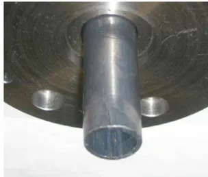
SIMULATION OF TUBE EXTRUSION
In order to check the accuracy and robustness of the method, a simulation of a real extrusion tube of 11mm external diameter and 2mm thickness has been done, and
the results are compared with the experimental ones. The tube is made of lead, since this material behaves as viscoplastic at low temperature, so extrusion can be done at room temperature. Before performing the extrusion ex-periment, a complete series of material tests have been done in order to characterize its properties. On the sim-ulation, the viscoplastic behavior has been modeled with the equation σ= 60d0.1, where d is the equivalent strain rate defined as d=q2
3ε: ε.
In a previous paper [11], the pressure inside the extrusion zone was measured experimentally using a proper equip-ment. Then, this measure was used to calibrate a commer-cial FE code in order to rebuild the pressure distribution all over the extruded material. In this way, it was shown that the required welding pressure threshold is about 150 MPa for the investigated case.
On the welding simulation, the modified α-NEM code has been used, imposing the welding pressure of 150MPa. Due to symmetry, only one quarter of the profile has been simulated using a cloud of 2580 nodes to create the initial
α-shape.
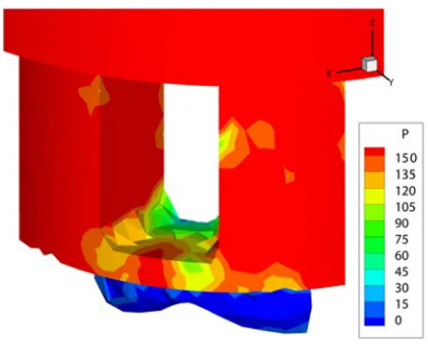
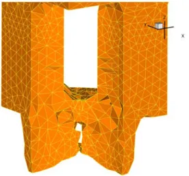
Figure 7 shows the pressure value on the welding chamber area. It can be seen that only one region, far from the exit area, has a pressure higher than 150MPa. Since material in this area doesn’t flow through the exit, this weld is not propagated and the welding won’t take place. Figure 8 shows how the weld is not created and a crack appears. Results are in agreement with experimental ones, shown in figure 9.
Figure 7: Simulated pressure.
5
CONCLUSIONS
Up to now the FE codes have been used to simulate the process but the unavailability to model the welding line evolution is one of the main drawbacks of this approach. Although the Natural Element Method together with the
α-shapes has been already used to simulate extrusion
pro-cesses and many other propro-cesses with free surfaces, it is the first time it is used to study the welding lines formed in
Figure 8: Simulatedα-shape.
Figure 9: Experimental results.
the extrusion of hollow profiles. Taking into account the history of the nodes and thanks to the meshless character-istic of the method, it is possible to modify the α-shapes to detect when the welding line is well created.
Both the academical example and the simulation corre-sponding to the real experimental test, confirm that the objective of simulating the behavior of the welding line is fulfilled.
REFERENCES
[1] J. Braun and M. Sambridge. A numerical method for solving partial differential equations on highly irregular evolving grids. Nature, 376:655–660, 1995.
[2] R. Sibson. A Vector Identity for the Dirichlet Tesselation. Mathematical Proceedings of the
Cambridge Philosophical Society, 87:151–155,
1980.
[3] H. Hiyoshi. A numerical comparison of the natural neighbor interpolation and the finite element method. In K. Sugihara, editor, International
Symposium on Voronoi diagrams in Science and Engineering, pages 1–10. University of Tokio,
2004.
[4] N. Sukumar, B. Moran, A. Yu Semenov, and V. V. Belikov. Natural Neighbor Galerkin Methods.
International Journal for Numerical Methods in Engineering, 50(1):1–27, 2001.
[5] H. Hiyoshi and K. Sugihara. Two generalizations of an interpolant based on Voronoi diagrams.
International Journal of Shape Modeling, 5(2):
219–231, 1999.
[6] H. Edelsbrunner and E. M¨ucke. Three dimensional alpha shapes. ACM Transactions on Graphics, 13: 43–72, 1994.
[7] E. Cueto, M. Doblar´e, and L. Gracia. Imposing essential boundary conditions in the Natural Element Method by means of density-scaled
α-shapes. International Journal for Numerical Methods in Engineering, 49-4:519–546, 2000.
[8] H. Valberg. Extrusion welding in aluminium extrusion. International Journal of Materials and
Product Technology, 17, 7:497–556, 2003.
[9] L. Donati, L. Tomesani, and G. Minak.
Characterization of seam weld quality in AA6082 extruded profiles. Journal of Materials Processing
Technology, 191:127–131, 2007.
[10] H.H. Jo, S.K. Lee, S.B. Lee, and B.M. Kim. Prediction of welding pressure in the non-steady state porthole die extrusion of Al7003 tubes.
International Journal of Machine Tools and Manufacture, 22:753–759, 2002.
[11] L. Filice, F. Gagliardi, and F. Micari. A laboratory scale equipment to relieve force and pressure in cold extrusion of lead hollow components. Key
Engineer. Mater., 367:137–144, 2008.