HAL Id: hal-00848689
https://hal-mines-paristech.archives-ouvertes.fr/hal-00848689
Submitted on 27 Jul 2013HAL is a multi-disciplinary open access
archive for the deposit and dissemination of sci-entific research documents, whether they are pub-lished or not. The documents may come from teaching and research institutions in France or abroad, or from public or private research centers.
L’archive ouverte pluridisciplinaire HAL, est destinée au dépôt et à la diffusion de documents scientifiques de niveau recherche, publiés ou non, émanant des établissements d’enseignement et de recherche français ou étrangers, des laboratoires publics ou privés.
Error Reduction in Slope Stability Assessment
Jean-Alain Fleurisson, Roger Cojean
To cite this version:
Jean-Alain Fleurisson, Roger Cojean. Error Reduction in Slope Stability Assessment. Jayanta Bhat-tacharya, H. Lieberwirth and Bern Klein. Surface Mining Methods, Technology and Systems. Volume 1, Wide, 41 p., 2014, 978-81-909043-8-8. �hal-00848689�
1
Error reduction in slope stability assessment
Jean-Alain Fleurisson and Roger Cojean
MINES ParisTech, Centre de Géosciences, Fontainebleau, France
1. Introduction
Slopes in quarries and open pit mines, as well as all the types of embankments (stockpiles, tailing dams, waste dumps) resulting from mining and mineral processing activities, must be considered as "geotechnical structures". Therefore, the design and implementation of these structures must be conducted with all consideration.
Considering an economical plan, the selection of reasonable slope angle for excavations in open pits is crucial as it affects the stripping ratio (ratio between waste and ore tonnages) and/or the tonnage of recoverable ore with consequences on the benefits or return on investment of the mining operations.
In terms of safety, various disasters can be mentioned (e.g. Failure of the waste dump at Aberfan in Wales in 1966, many failures in tailing dams on every continent or failure in open pit mines and quarries) in which safety and profitability of the mining operations were often adversely affected by various slope instabilities.
Finally and with respect to environmental issues, long-term stability of slopes in quarries, open pit mines and mainly embankments must be maintained, at the end of operations and even after that.
So, slope design is the process of determining the optimum slope angle for input into pit design, that is to say the slope angle at which the net benefit is the highest. Mining at flatter angle will result in higher stripping costs and reduced ore recovery. Conversely, mining at steeper angle would result in slope instability costs higher than the increased ore recovery. The Earth and Mechanical Sciences are the primary focus of this issue, in particular, disciplines such as: engineering geology, geotechnical engineering, soil mechanics and rock mechanics, hydrogeology and underground water.
The main aim of this section is to highlight the basic principles of the slope design process. Though, these principals can be well presented and understood, however it is not enough and it is always necessary to involve slope stability experts; More advanced and sophisticated scientific methods can be only applied by an expert; they have access to laboratory facilities; they have long-time experiences on field studies so they have better understanding of each project uniqueness; considering above, experts can provide more comprehensive definition of the problem and consequently more reliable designs. It is again necessary to emphasize that each case study is always a new special and unique case. This section also presents different cases of difficulties encountered in open pit slope design.
2
2. Methodology for design and implementation of slopes in open pit mines
2.1 Principles of slope design
It is important to implement a well-defined methodology applicable for various categories of both mine and embankment slope. Such methodology should be conducted according to the following four phases (Cojean and Fleurisson, 2005):
2.1.1 Phase 1: Acquisition of geological, geomechanical and hydrogeological knowledge by observation and measurement
This phase of analysis requires knowledge from all the previously mentioned disciplines; However, whether the material, in which slopes will be excavated or which will support the waste disposals, shows behaviour of soil or rock mass, the geological approach is essential in order to analyze material behaviour. The geologist identifies the petrographic nature of the material (rock or soil) and their state of weathering and fracturing. These data are essential for the characterization of mechanical properties of material. It also provides the spatial variability of these parameters at the scale of the mass. Similarly, the geologist identifies geological structures of the deposit. This will be used to determine precise relationships between different parts of the deposit and also to illustrate the possible mechanisms of deformation or failure.
This preliminary geological approach allows planning and optimizing of geological and geotechnical field investigation using drilling operations or geophysical methods. It usually includes the followings:
Destructive drilling with recording of the drilling parameters;
Core drilling, taking intact samples for geomechanical laboratory studies; Boreholes geophysical logging.
Also, it is always necessary to install piezometers inside the boreholes to detect level of the groundwater.
In some cases, performing subsurface geophysical surveys (seismic, electric, gravity, etc ...) combined with some boreholes can also be helpful. Sometimes shallow excavations using hydraulic shovels can provide interesting information which can be also cost-effective.
From the early stage of the project, it is recommended to consider a "geotechnical enhancement" of all the drillholes performed for deposit prospecting or resource evaluation. This is for the sake of total cost and also better programming of exclusively geotechnical reconnaissance.
Cuttings from destructive drilling or, better, intact core samples are used to determine the mechanical and petrophysical parameters necessary for further stability studies. This analysis is carried out by laboratory tests. Using these tests it is possible to determine various useful parameters including petrophysical parameters, deformability characteristics and mechanical strength of the materials, density, different model of deformation, cohesion and internal friction angle of soil and shear strength parameters of discontinuities.
Detailed methodology for rock mass characterization is given in AFTES (2003) and Fleurisson (2001).
3
In some cases it may be useful to perform in-situ mechanical tests in boreholes (pressuremeter or dilatometer, etc...) or on surface (shear tests of materials or rock mass discontinuities analysis, etc...).
2.1.2 Phase 2: Determination of potential mechanisms of deformation and failure
The analysis of geological structures and geotechnical parameters of the considered material, as well as the analysis of mechanical stresses generated by the mining activities (excavation in quarry or open pit mine, weight of waste dump, hydraulic load generated by a tailing dam) lead to identify the most critical mechanisms of deformation and failure. In general, the simplification of these critical mechanisms using homogenization and generalization techniques is required in order to set up physical and then numerical models that allow the quantification of the risk of failure. Such simplification processes inherent to any numerical modelling should not be underestimated and should be used with caution. In each situation, we must be able to estimate the difference between results produced by the model and reality.
2.1.3 Phase 3: Modelling – Deformation and safety factor calculations
In this section, the geological, hydrogeological and geotechnical data required for further analysis are discussed.
2.1.3.1 Background of the study
These studies should include the followings:
a) Geometric scales of the case: What is the main focus of the problem in terms of scale: the stability of a single bench, a set of three, four, five benches, or the entire pit side, 100 m, 300 m, 600 m or more in height? What is the target: the stability of the waste dump alone or the stability of the waste dump and its supporting ground, and to what depth? In fact, different geometric scales and also different corresponding deformation and failure mechanisms should be always taken into consideration.
b) Type of mechanical loading: Is the problem focusing on slope stability during the mining operations phase? In this case, short and medium term stability is considered where it is possible to ignore some deformation at acceptable rate or some localised failure, ensuring that these neither affect the safety of staff, nor adversely affects the operation. Is the main focus on the stability of slopes of final pit at the end of the mining operation and after reclamation processes? In this case long-term stability is considered which needs more study on the stability criteria, and also considering different scenarios describing possible changes in geotechnical properties of the materials over the time (weathering of discontinuities wall, creep phenomenon and reduction of shear strength in clay soils, etc.) and also changes in the rock mass hydraulic conditions. Is the problem focusing on stability in extreme conditions (hazard studies)? This case asks for studying especial hydraulic loading (for example, unusually high underground water levels) or specific dynamic loadings (earthquake)? c) Accuracy of geological, hydrogeological and geotechnical data collected for the
study: We are always able to have only a limited knowledge of the real natural
4
The spatial variability of geological parameters: lithofacies, thickness, mechanical and petrophysical properties;
Complexity of the discontinuity sets in the rock mass, it should be simplified in order to use existing models;
Lack of information defining water levels inside the soil and rock masses. In order to overcome the problem of accuracy in some datasets, it is necessary to perform a parametric analysis considering a realistic variation range for the poorly known parameters, and also by comparing responses from the expected deformation and failure in the soil or rock masses.
2.1.3.2 Calculation Methods
After the definition of the problem, calculation of deformation and stability calculations can be undertaken.
a) Safety factor calculations: based on the theory of limit equilibrium, it is possible to
evaluate the stability of a solid using the concept of factor of safety (FoS).
Considering a sliding mechanism along a potential failure surface, we could compare a resisting force (maximum shear strength in the material at the time of failure) against a driving force. The latter is balanced with the shear stress acting along the potential failure surface at the current state of the mass. Hence the factor of safety can be defined as:
FoS=Maximum resisting force (strength) Driving force (acting stress) from that:
for FoS > 1, the strength exceeds the stress, the slope is stable; for FoS ≤ 1, the stress exceeds the strength, the slope is unstable. Similarly, for a circular mechanism, safety factor can be defined as:
FoS=Maximum resisting moment Driving moment
For more geometrically complex mechanisms, it is possible to use other methods defining other types of safety factors.
Considering a wide range of available software, these analyses are easy and quick, that makes it possible to study many different situations in a short period of time. Moreover, some software packages are also able to integrate the effect of the mechanical reinforcement (soil nailing, rockbolts or grouted cable bolts) into analysis.
However, we must be cautious about the simplicity of the concept of safety factor and do not forget that it oversimplifies the process of deformation and failure. In particular, the concept of progressive deformation or progressive failure is not taken into account in analysis using factor of safety.
In addition, it is still necessary to adapt the theoretical level of safety according to the accuracy of input data. For short-term stability analyses, safety factors of 1.2 to 1.3 would be acceptable, while for long-term stability, factors of safety usually range between 1.4 and 1.5.
5
It is wise to perform these calculations using both average values of mechanical parameters and also lower realistic values. These latter values are always the basis of the design process. b) Deformation calculations: the calculation of the deformation of a soil or rock mass in
response to a mechanical or hydraulic loading requires a high level of knowledge of the existing geomechanical objects (mass geometry, heterogeneity and anisotropy, mechanical behaviour), around the initial conditions (state of stresses in the mass, etc..) and the boundary conditions (mechanical and hydraulic conditions).
All masses, in some states, resemble a continuous media (soils in general) or discontinuous
media (rock mass in general). Depending on whether the mass behaviour is close to a
continuous media or a discontinuous media, it is possible to use either physical models with a continuous approach and its associated numerical methods such as finite elements (FEM) or finite differences (FDM), or other physical models and numerical methods suitable for discontinuous media such as distinct element method (DEM).
Using these results, it is possible to obtain an estimation of the mass stability, to advocate changes during the project (slope angles or plan and profile curvature of slope) in order to reduce the stress in certain part of the mass or to propose suitable reinforcement methods or drainage systems.
Although FEM or FDM calculations have become more feasible thanks to the improvements in software and computer technology which have considerably reduced the calculation times and costs during the last twenty years, they are still time-consuming compared to factor of safety calculation and mainly required much more data related to constitutive laws of materials, boundary conditions and initial in-situ state of stresses. Their use should be limited to complex and well informed cases where failure mechanisms cannot be correctly evaluated or deformation and stress distribution within the mass in response to mechanical or hydraulic loading is the main concern. In more standard cases, the calculation of safety factor is sufficient.
2.1.4 Phase 4: Methods of reinforcement and monitoring
In general, different methods of reinforcement can be considered optimising a quarry or mining project. In fact, for a same level of safety, it is possible to propose different slope design, integrating or not reinforcement systems. The corresponding stripping ratio and the additional costs of these reinforcement systems should always be considered in the same economic approach as the main design itself. These additional costs can be due to:
Volumes of waste material to be extracted from the pit (lowest slope or material unloading at the top of slope), and to be dumped in the waste disposal;
Volumes of backfilling or buttress material placed at the toe of slope;
Drainage system on surface or watertable drawdown system including drainage galleries, pumping wells and sub-horizontal drains;
Reinforcement using rockbolts and grouted cables for rock mass, or soil nailing. The final decision rests with the mine operator; however the slope stability experts can offer various scenarios, quantify gains or losses related to stability for each one, and also the relevant costs of these systems and their implementation.
Finally, in many cases, monitoring of slope using a wide range of monitoring instruments may be recommended: topographic monitoring, controlling of underground water levels,
6
measurements of displacement and deformation during drilling, etc... In all large mining or civil engineering projects, monitoring has become the ally of the modelling and calculations. In these cases, as a large initial investment should be made early in the life of the project, then a continuous dialogue is needed between measurement and modelling and results should be interpreted in a well-understood geological framework. This approach is known as the observational approach and means that the instrumentation data are used to provide feedback on performance, mitigate potential instability and/or re-design as necessary. These results are always useful to the mine operation, economically and also in terms of safety.
2.2 Methods of stability analysis and slope design
2.2.1 Introduction
The calculations are based on mechanics of continuous media, soil and rock mechanics and underground water. Following mechanical parameters and constitutive laws play a role in any design slope (partial list):
Internal friction angles and cohesion of soil; Uniaxial compressive strength of rocks;
Deformation modulus in compression and shear of soils and rocks (rock material); Mechanical behaviour of discontinuities in compression and shear conditions; Laws of hydro-mechanical coupling in soils and rock masses.
In opencast mines and quarries, the effect of blasting on a reduction of mechanical parameters must be taken into account for any calculations, although these effects may be limited by using some blasting techniques: pre-splitting, smooth blasting (controlling the explosive powder factor and borehole charge), and control of implementation of mass blasting.
Moreover, the role of water as a triggering factor must be emphasised. The determination of level of underground water in the soil is relatively easy; in contrast, the variability in space and always complex hierarchical classification of discontinuities sets make it very difficult to identify underground water level in rock masses.
Finally, the role of time should not be underestimated. Over time, multiple processes can reduce mechanical parameters of the mass. Weathering occurs in openings inside the body of mass which result of what is called "the elastic rebound of the rock mass" in response to the excavation. Creep deformation process caused by gravity acting on slope results in opening of discontinuities. Consequently, weathering may develop very rapidly inside these openings. The result would be a decrease in cohesion due to the weathering of rock bridges in the discontinuities, leaching of infilling material in discontinuities and weakening of cohesion in the soil. The friction angle in soil also decreases due to the expansion of the rock mass. In rock masses, friction angle decreases due to a partial reduction of the interlocking of the discontinuity walls and also weathering of the contact points of the discontinuity walls.
2.2.2 Some basic concepts
The above considerations and comments can be illustrated considering the equilibrium of a block sliding on a plane failure surface inclined to an angle α (Figure 1). The block is delimited by the slope with a slope face angle ψ and the discontinuity plane of length L.
7
Figure 1: Equilibrium of a block sliding on a plane failure surface
The geological structure giving rise to the plane surface (the discontinuity set strikes parallel to the slope face and the dip angle of the discontinuity is lower than the slope face angle) represents the predisposition factors for this failure mechanism.
The analysis of the mechanical equilibrium conditions of the block will allow defining the triggering factors of the failure.
The equilibrium of the system represented in Figure 1, gives the following equation: 𝐹 𝑖 = 𝑊 + 𝑅 + 𝐸 = 0 (1)
where 𝑊 is the weight of the block
𝑅 is the reaction force of the support ground which can be divided in a tangential component 𝑇 parallel to the plane failure surface and a normal component 𝑁 perpendicular to the plane failure surface;
𝐸 is a dynamic force representing dynamic loading induced by earthquake or blasting The following equations can also be written:
𝑊 =𝛾𝐻22 cot 𝛼 − cot 𝜓 =𝛾𝐻22sin 𝛼 sin 𝜓sin (𝜓−𝛼) (2) 𝐸 = 𝑘 𝑊 (3)
where is the specific weight of the material k is a seismic loading factor
Considering the water force U equal to the resulting force of the water pressure acting along the discontinuity plane, it comes
𝑁 = 𝑁′ + 𝑈 (4)
8
Where N' and T' are the effective normal and tangential component (according to Terzaghi relationship)
From equation (1), it can be derived:
N = W.cosα - E.sinα = W.(cosα - k sinα) (6) T = W.sinα + E.cosα = W.(sinα - k cosα) (7)
According to the theory of limit equilibrium, it is possible to define a driving force DF and a resisting force RF, and therefore a factor of safety defined as the ratio FoS = RF/DF.
The driving force DF likely to induce the failure is parallel to the potential sliding direction and is equal to:
DF = W.sinα+ E.cosα= T (8)
As the block is in equilibrium, DF is balanced with the actual shear force T acting along the plane surface.
The resisting force RF represents the maximum shear strength along the failure surface at the time of failure.
RF = τr . AB (9) where
AB=sin αH (10)
and r = C + . tan = C + ( − u). tan (11)
where r is the shear stress at failure
C is the cohesion and the angle of friction of the discontinuity plane the normal total stress acting on the discontinuity plane
the normal effective stress acting on the discontinuity plane u the pore water pressure
It comes then:
RF = C.AB + (N – U).tan (12) Hence the factor of safety can be defined as:
𝐹𝑜𝑆 = 𝑅𝐹𝐷𝐹 =𝐶.𝐴𝐵+(𝑁−𝑈) 𝑡𝑎𝑛 𝜑𝑊 𝑠𝑖𝑛 𝛼+𝐸 𝑐𝑜𝑠 𝛼 (13) 𝐹𝑜𝑆 = 𝐶.𝐴𝐵+(𝑊(𝑐𝑜𝑠 𝛼−𝑘 𝑠𝑖𝑛 𝛼)−𝑈) 𝑡𝑎𝑛 𝜑𝑊 (𝑠𝑖𝑛 𝛼+𝑘 𝑐𝑜𝑠 𝛼) (14)
U is the uplift force due to water pressure on the failure surface. It depends on the water level and the drainage condition of the discontinuity plane (See 2.2.2.3)
9
The respective roles of the parameters involved in this formula can be highlighted considering the various extreme situations hereafter.
2.2.2.1 Role of the angle of friction
Let us consider the situation where the slope is dry, where there is no seismic risk and the discontinuities have no cohesion (planar and smooth discontinuity walls without any infilling material):
C = 0 U = 0 k = 0
The factor of safety becomes:
𝐹𝑜𝑆 = 𝑊 𝑐𝑜𝑠 𝛼 𝑡𝑎𝑛 𝜑𝑊 𝑠𝑖𝑛 𝛼 = 𝑡𝑎𝑛 𝜑𝑡𝑎𝑛 𝛼 (16)
The equilibrium is therefore possible only if > α. The angle of friction plays an essential role on the slope stability. Moreover, when the cohesion is equal to zero, the block geometry and volume do not have any influence on the stability.
2.2.2.2 Role of the cohesion
Let us consider the situation where the slope is dry, where there is no seismic risk and the discontinuities exhibits cohesion (highly rough discontinuity wall or clayey infilling material or presence of rock bridges):
C 0 U = 0 k = 0
The factor of safety becomes:
FoS= C.L+W cos α tan φW sin α = γHC sin (ψ-α) sin α2 sin ψ +tan φtan α (17)
Compared to the previous situation, the cohesion brings an additional strength through a term proportional to the ratio C/.H. The higher the slope, the larger the potentially unstable volume and therefore the lower the influence of the cohesion. This represents a scale effect.
2.2.2.3 Influence of water
Let us consider the situation where there is no seismic risk and the discontinuities have no cohesion (planar and smooth discontinuity walls without any infilling material), but there is water in the discontinuity and eventually the tension crack:
C = 0 U 0 k = 0
The factor of safety becomes:
10
So, compared to dry conditions, the presence of water within the discontinuity plane will reduce the factor of safety.
Several possible hydraulic situations corresponding to different values of U can be considered depending on the ability of the discontinuity plane to drain water as illustrated in Figure 2 and Table 1.
Figure 2 : Schematic possible drainage conditions and pore pressure distribution along the discontinuity plane
Table 1: Value of pore pressure resulting force depending on drainage conditions along the discontinuity plane
Drainage conditions Water pressure resulting force λ value [a] No drainage at the bottom of the
discontinuity (no drainage, very pessimistic situation)
U= γwH2
2 sin α=λ U0 λ=1
[b] One drainage point at the bottom of the discontinuity (low drainage situation) U= γwH 2 4 sin α=λ U0 λ= 1 2 [c] Two drainage points at the bottom
and at a point of the discontinuity located at an elevation of H/2 (medium drainage situation)
U= γwH2
8 sin α=λ U0 λ=
1 4 [d] Four drainage points at the bottom
and at points of the discontinuity located at an elevation of H/4, H/2 and 3H/4 (high drainage situation)
U= γwH
2
16 sin α=λ U0 λ=
1 8 The factor of safety can be then written as a function of the λ value corresponding to the various drainage possible conditions:
11 FoS= 1-λγw γ sin ψ sin (ψ-α) cos α tan φ tan α (19)
With the following average parameters:
Cohesion in the discontinuity plane C = 0 kPa Rock mass specific weight γ = 25 kN.m-3
Water specific weight γw = 10 kN.m-3
Slope angle ψ = 60°
Discontinuity dip angle α = 30°
The values of the factor of safety corresponding to the various considered hydraulic conditions are given in Table 2. It underlines the strongly destabilizing action of water and therefore the interest of drainage methods for slope reinforcement.
Table 2: Value of pore pressure resulting force depending on drainage conditions along the discontinuity plane
Drainage conditions Factor of Safety
Without any water in the discontinuity plane (dry
conditions) FoS=
tan φ tan α [a] No drainage at the bottom of the discontinuity (no
drainage, very pessimistic situation) FoS= 0.2 tan φ tan α [b] One drainage point at the bottom of the
discontinuity (low drainage situation): FoS= 0.6 tan φ tan α [c] Two drainage points at the bottom and at a point of
the discontinuity located at an elevation of H/2 (medium drainage situation):
FoS=0.8 tan φ tan α [d] Four drainage points at the bottom and at points of
the discontinuity located at an elevation of H/4, H/2 and 3H/4 (high drainage situation):
FoS= 0.9 tan φ tan α
2.2.2.4 Role of a dynamic loading
Let us consider the situation where the slope is dry, there is no seismic risk and discontinuities have no cohesion (planar and smooth discontinuity walls without any infilling material):
C = 0 U = 0 k 0
The factor of safety becomes:
12 If α = 30° and k = 0.1: FoS = 0.80 tan / tan α If α = 30° and k = 0.2: FoS = 0.67 tan / tan α If α = 30° and k = 0.3: FoS = 0.54 tan / tan α If α = 30° and k = 0.5: FoS = 0.38 tan / tan α
As consequence, a dynamic loading due to blasting or earthquake can strongly affect the slope stability, especially for very small volumes located at the top of the slope or the bench where amplifications of the seismic signal may happen due to topographic site effects.
It must be noticed that, in this so-called pseudo-static analysis, the dynamic loading is modelled as a constant inertia force applied to the centre of gravity of the unstable block and is a very imperfect representation of the dynamic loading. Resulting values of the factor of safety are therefore pessimistic.
This approach however underlines the necessity to reduce as much as possible the overbreaks or back effects induced by blasting using smooth blasting and pre-splitting when approaching the ultimate pit slope including reduction of the unit charge (weight or energy of explosive per delay), geometry and quality of the drillholes and quality control of the explosive loading.
2.2.2.5 Role of the rock mass degradation
Numerous processes occurring over time may induce degradation of the rock mass and reduction of their mechanical properties such as cohesion and angle of friction.
Rock mass weathering may result from the opening of the rock mass discontinuities due to excavation processes, action of water and alternation of freeze-thaw periods. Rainfall water may therefore enter inside the rock mass and rapidly develop the weathering processes.
It results in a reduction of the cohesion by failure of rock bridges, leaching of infilling material in the discontinuity and decreasing of the cohesion bonds in the soil material. Angle of friction may also decrease as consequences of dilation phenomena in soil mass, loss in joint wall interlocking and subsequent increase in the stresses on the contact points of the discontinuity walls leading to an accelerated alteration of the rock material. The global dilation of the rock mass contributes to the global decreases in its shear strength resulting in the development of progressive deformation and failure mechanisms.
Overbreaks due to explosive action may also accelerate all these processes.
It is therefore necessary to consider the effect of time as a key factor in the long term stability of the slope.
2.2.3 Some types of failure mechanisms
Few mechanisms presented in Figure 3 are highly dependent on the geological mass structure, where engineering geologists have to identify the surface and volumes with greatest deformability and lowest shear strength.
2.2.3.1 Slide and failure surface along one or more discontinuities or discontinuity sets These types of sliding occur in rock mass and involve classical mechanisms of shearing along discontinuities or more complex mechanisms such as arching, bending, toppling or buckling of rock slabs. More or less rigid rock material, and more or less weathered discontinuities walls play a critical role in the occurrence of these mechanisms. Among the elementary failure mechanisms, we could mention:
13
Figure 3: Some elementary processes of slope failure: (a) plane failure, (b) wedge failure, (c) toppling failure, (d) circular failure (modified after Hoek and Bray, 1981)
The plane failure (Figure 3a): this is the simplest failure mechanisms consisting of sliding
along a single plane striking nearly parallel to the slope and dipping flatter than the slope angle. The plane failure may correspond to bedding joints in sedimentary formations, foliation or schistosity plane in metamorphic formations or a fault or a lithological contact between clayey weathered rocks and bedrock.
The step failure: it occurs when there is a discontinuity set dipping into the pit in the plane
failure orientation, but no individual discontinuity is long enough to form a plane shear geometry. Sliding is assumed to occur along discontinuities in the plane shear orientation (master joint set) and separation along discontinuities approximately perpendicular to the master joint set or tensile fracture of the rock material between the master joints.
The wedge failure (Figure 3b): the wedge geometry results from the intersection of two
planar geological structures to form a prism of material. Sliding may occur along the intersection line of the two planes, or on one of the two discontinuities with separation along the other one.
The various types of toppling failure mechanisms (Figure 3c) may be postulated where the
rock mass exhibits steeply dipping structures that results in blocks with a large height-to-thickness ratio. For toppling to occur, the centre of gravity of the block must be outside the toe of the block. Therefore, sliding along natural discontinuity or breaking the rock material at the toe must occur before toppling is initiated.
The various kinds of bilinear slab failure mechanisms (Figure 4): where there is bedding
or foliation parallel to the pit, slope instability may occur even if the structures are not daylighted. The possible failure mechanisms are crushing at the toe, or two block geometry formed by joint at the toe, and buckling.
Sometimes in jointed rock masses, some particular blocks play the critical role of “key blocks” in the overall balance of the set of blocks. All mechanical methods of reinforcement using bolts or anchors should take advantage of this situation.
14
Figure 4 : Footwall elementary slab failure mechanisms (after P.M. Hawley, 1985)
2.2.3.2 Non-planar failure surfaces
The rotational failure (Figure 3d)
In a soil or highly jointed and weathered rock mass slope, where there are no geological structures to control the failure, the most unstable failure surface is approximately a circular arc. This circular failure surface results from a process of localization of deformations. It is the archetype of landslides; however the specific shape of this failure surface and the associated failure mechanism cannot be generalized.
The location of the critical or most unstable circle depends on the material properties and must be found by iterative solutions of trial circles. The stability of the circular surface is usually analyzed by the method of slices. The volume delimited by the topographic surface and the circular failure surface is divided into a series of vertical slices so that the failure surface may be approximated by planar segments. The driving and resisting forces acting at the base of each slice as well as the interslice forces along the slice limits are calculated. Force and moment equilibrium of each slices are considered, and result in the calculation of a factor of safety. Different calculation methods corresponding to different necessary assumptions on the interslice forces may provide different value of the factor of safety. Among them, the simplified Bishop calculation method is the most widely used and accurate.
Sliding along a polygonal surface
Very often, a sliding surface (generally in convex shape) follows different sources of weakness within the mass, for instance: pre-existing discontinuities, stratigraphical joints or in depth weathered zones. The surface is therefore a mixed mode failure in which part of the failure surface is structurally controlled and part is failure through the soil or rock material. Study of this type of slides leads to create software similar to those used for the circular
15
failure in soils. The method of slices is also used to calculate the factor of safety according to simplified Bishop or Janbu calculation methods, with, however, a lower level of confidence in the results considering the large amount of generalization imposed to the assumed situations. 2.2.3.3 Creep deformation in soils and rock masses
Sometimes, the mechanism of deformation does not quickly progress to a stage of localization of deformation along a plane of failure. Creep deformation affects a vast volume of ground that can then evolve slipped masses. These processes often develop at the toe of a too steep fractured rock face, naturally pre-cut by large vertical joints or faults, overlying a layer of soft material (marl or clay).
2.2.3.4 Complex deformation and failure mechanisms
In many cases, the discontinuous nature of the rock mass as well as the mechanical behaviour of the rock material itself plays an important role in the process of deformation and failure. In this case, especially when large volumes are involved, very complex mechanisms may occur and are difficult to characterize. In such cases, numerical modelling emphasizing the discontinuous or continuous aspects of the rock mass allows describing the most likely theoretical process of deformation. The implementation of these models, however, requires a comprehensive knowledge of many mechanical parameters. From the earliest stages of the project, monitoring systems and instrumentation must be installed to monitor the behaviour of solid in order to make the best use of modelling.
Depending whether the continuous or discontinuous aspect of the mass under consideration can be emphasized, appropriate calculation methods using finite elements or finite differences in the first case, or distinct elements in the second case will be used.
In addition, the concept of progressive deformation and failure has to be considered for specific materials such as over-consolidated clays. This concept leads to consider in a detailed way the actual mechanical parameters (peak or residual shear strength) that have to be used in limit equilibrium methods.
2.2.4 Slope design
There are three major components of a pit slope: bench configuration, interramp slope, and overall slope (Figure 5).
16
The bench configuration is defined by the bench face angle, the bench height, and bench width. The interramp angle is the slope angle produced by a given number of benches. Where there are haul roads, working levels, or other wide benches, the overall slope angle is the angle of the line from the toe to the crest of the pit; the overall slope angle will be flatter than the interramp angle.
Steps in slope design are the following: Define design sectors;
Conduct a bench analysis to determine the maximum interramp slope;
Conduct interramp design analysis using economic criteria for the selection of interramp angles;
Evaluate the resulting overall slope for potential instability, and modify the design if required.
2.2.4.1 Design sector
To conduct stability analyses and develop optimum slope angles for input into pit design process, the proposed pit must be divided into design sectors that are sections of the pit with similar geological and operational characteristics. This selection is based on several criterions: the structural domain, the wall orientation and operational considerations.
Since a pit geometry is required to define design sectors, slope design is iterative with mine planning.
2.2.4.2 Bench design
Bench faces stability in rock masses is mainly controlled by the small to intermediate scale discontinuity sets such as joints. As they are normally mined as steep as possible, rock falls or ravelling can be expected. Thus, it is customary that catch benches be left in the pit wall to retain rock falls and ravelling.
2.2.4.3 Interramp design
In rock masses, the stability of interramp is mainly controlled by intermediate to large scale discontinuities such as joints, bedding or schistosity planes and faults. Major structures such as faults or bedding planes can usually be specifically located in space while smaller structures such as joints must be considered as a statistical representation of the real structures present in the rock mass. Factor of safety and associated possible failure volumes can then be calculated for specific slope angle and slope heights using analytical models corresponding to the appropriate failure mechanisms.
In soil masses, standard stability analysis based on rotational failure mechanism must be performed.
An interactive process is used to design the interramp geometry so that the corresponding factor of safety is higher than a value of reference or potential unstable volumes are lower than an acceptable value in terms of safety of the working personnel and impacts on the mining operation.
2.2.4.4 Overall slope
As the overall slope angle is usually flatter than the interramp slope because of ramps and other step-outs, its stability is normally better than the interramp slope, except for stress-induced failure or failure modes not analyzed for the interramp. At this scale and if the rock mass does not include very persistent structures, it can be homogenized and then considered
17
as a homogeneous and continuous medium which mechanical parameters will depend on rock material, structural pattern and discontinuity surface conditions. For example, Hoek & Brown classification system can be used to derive the mechanical properties of the rock mass (Hoek and al., 2002, 2007).
Rotational failure analysis should be run for the overall slope even in rock mass to be sure that it would not be a critical failure mode. In the case where one part of the failure surface could be structurally controlled, then sliding along a polygonal surface or any other appropriate failure mechanism has to be considered.
Calculation in deformations using FEM or FDM can also be used to check if plastic zones develop inside the rock or soil mass and to calculate stress and strain distributions, especially in the close vicinity of the excavated slope. Specific attention should be given to the toe of the slope or to zones with steeper geometry where high stress concentrations are usually located giving rise to possible development of progressive failure. Some FEM or DEM software also allows the calculation of factor of safety along predefined surfaces.
2.3 Methods of stabilization of soil and rock slopes
Approaches to the design of stable slopes can be categorized as follows: Reduce the forces tending to cause the movement;
Increase the forces resisting to the movement. 2.3.1 Reduction of driving forces
Since the forces tending to cause movements downslope are essentially gravitational, a simple approach to increase stability is to reduce the mass of soil involved in the slope. Techniques for this include flattened slopes, benched slopes, reduced excavation depths, surface and subsurface drainage and lightweight fills. The stability of embankment slopes cannot necessarily be approached in the same manner as that of natural or excavated slopes. For example, the stability of slopes of embankment tends to increase with time because of consolidation and the resulting strength increase of the fill and foundation. A notable exception to this would be embankments composed of degradable shales and other soft rocks, which may deteriorate with time and result in settlement or even failure. In natural or excavated slopes, however, the long-term stability may be significantly less than the stability at the end of the construction.
2.3.1.1 Change in slope geometry
Early in the design stage, cut-and-fill slopes should be evaluated for potential instability. Changes in slope geometry often result in reduction of driving forces. Another technique for reducing the driving forces is the partial removal or excavation of a sufficient quantity of slope material at the top of the slope to ensure stability of a potential sliding mass. In some cases, benching is appropriate. Benches also serve to control surface runoff and provide work areas for installation of sub-horizontal drains.
2.3.1.2 Drainage
Drainage of surface water and groundwater is the most widely used and generally the most successful slope stabilization method. Drainage will both reduce the weight of the mass tending to cause the slope movement and also increase the strength of the materials in the slope.
18
Surface drainage measures require minimal engineering design and have to take into account two parameters: the amount of surface water flowing across the faces of the slopes and the amount of surface water seeping into or infiltrating into the head of the cut. Both of these conditions cause erosion of the faces of the slopes and increase the tendency for localized failures on the slope faces. Several measures to treat the surface of the slopes are available, such as seeding, sodding, mulching or using shotcrete, riprap, thin masonry, concrete paving, asphalt paving and rock fills.
Subsurface drainage measures are essential in order to lower the seepage forces. Subsurface drainage measures consist of lowering the groundwater table using drainage blankets and trenches, drainage wells, drainage galleries, adits or tunnels, sub-horizontal drains drilled either from the slope surface or from drainage wells or galleries and sub-vertical drains drilled upwards from drainage galleries. Most of these systems drain by means of gravity flow. However, pumps are can be used to remove water from low-level collector galleries or wells. Other less common techniques exist such as electro-osmosis, vacuum dewatering and blasting of rock slopes for improving natural drainage.
2.3.1.3 Geotextiles and geocomposites
Geosynthetic products can be used for drainage and slope stabilization. The geotextile filter can be designed for soil retention, system permeability and long term filtration characteristics. Geocomposites are products consisting of a geotextile filter to protect the drain and keep it free-flowing throughout its service life and a plastic net or core that provides in-plane drainage. Geocomposites can be installed in trenches on slopes, especially in areas where access is difficult.
2.3.2 Increase in resisting forces
Another type of measures for stabilizing slopes is to increase the resisting forces. They usually function by either applying a resisting force at the toe of a slope or increasing the internal strength of the soil.
2.3.2.1 Application of external forces
Such resisting forces are most often applied at the toe of the slope by a variety of methods including buttresses, counterweight fills and toe berms, structural retention systems such as cantilever and gravity retaining walls, externally braced walls or walls supported by anchors or tiebacks, soil nailing, root piles and drilled shafts and a variety of reinforced-soil systems.
2.3.2.2 Increase in internal strength
Techniques used to increase the internal strength of a potentially unstable soil or rock mass consist of subsurface drainage and soil or rock mass reinforcements.
Soil reinforcement include backfill systems with strip, sheet, grid or bar reinforcements, soil nailing, micropiles, pin piles and root piles.
Rock reinforcements allow minimizing the relaxation and loosening of the rock mass that may take place as a result of excavation and unloading. For this reason, reinforcement of rock slopes is most effective if it is installed before excavation; this process is known as
pre-19
reinforcement. Pre-reinforcement of a benched excavation can be achieved by installing bolts as each bench is excavated. Installation of fully grouted but untensioned bolts at the crest of the cut before excavation prevents loss of interlock of the rock mass. However, when blocks have moved and relaxed it is necessary to install tensioned bolts in order to prevent further displacements and loss of interlock. Three main aspects related to the design of a permanent tensioned rock-bolt installation must be considered; Firstly, a method of anchoring the distal end of the anchor in the drill hole has to be developed; Secondly, a known tension has to be applied to the bolt without creep and loss of load over time; Thirdly, the complete anchor assembly has to be protected from corrosion for the designed life of the project.
2.4 Mine deformation monitoring techniques
The main objective of any monitoring system is to detect deformation, its magnitude and extent. Data collected using such systems is also crucial as can be used in order to define the relationship between vertical and horizontal movements, determination of influence of time and also to monitor and predict damages induced by the deformation (Forrester and Aston, 1987).
Historically, a variety of surveying techniques have been used to monitor mine deformation. The principal monitoring instruments for local deformations are extensometers, crack meters and inclinometers.
Extensometers measure the axial displacement between a numbers of references points along the same measurement line. The extensometers can be installed either on slope surface or inside a borehole.
Crack meters are useful tools in case of the early detection of a deformation. These devices measure the displacement between two points on the surface that are exhibiting signs of separation. They are widely used due to their low cost and ease of implementation.
Inclinometers are used to measure the curvature of initially straight boreholes. This is typically accomplished by the use of a gravity operated tilt sensors. Several different configurations of boreholes inclinometers are available. Inclinometers are usually distinguished by their measurement sensors, such as vibrating wire transducers, differential wire transducers, servo-accelerometers or gravity activated electrolyte cells.
Piezometers are also of paramount importance as they measure the pore pressure of the groundwater within a geological structure. Excess in pore pressure is one of the main triggering factors of slope instability.
For large scale monitoring, levels, theodolites, electronic distance metres (EDM) and total station make possible to measure both the coordinates and changes of targets and control points together (Ashkenazi et al., 1980). Aerial or terrestrial photogrammetry is used to determine point coordinates, contour maps, cross-sections of the deformation and also the movement vectors (Chandler and Moore, 1989; Oka, 1998). Table 3 provides an overview of methods used in measuring surface displacements and their precision.
20
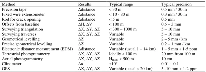
Table 3 : Overview of methods used in measuring surface displacements (After Gili et al., 1999)
Method Results Typical range Typical precision Precision tape Δdistance < 30 m 0.5 mm / 30 m Fixed wire extensometer Δdistance < 10 - 80 m 0.3 mm / 30 m Rod for crack opening Δdistance < 5 m 0.5 mm Offsets from baseline ΔH, ΔV < 100 m 0.5 – 3 mm Surveying triangulation ΔX, ΔY, ΔZ < 300 – 1000 m 5 – 10 mm Surveying traverses ΔX, ΔY, ΔZ Variable 5 – 10 mm Geometrical levelling ΔZ Variable 2 – 5 mm / km Precise geometrical levelling ΔZ Variable 0.2 – 1 mm / km Electronic distance measurement (EDM) Δdistance Variable (usual 1 – 14 km) 1 – 5 mm + 1-5 ppm Terrestrial photogrammetry ΔX, ΔY, ΔZ Ideally < 100 m 20 mm from 100 m Aerial photogrammetry ΔX, ΔY, ΔZ Hflight < 500 m 10 cm
Clinometer Δα ±10° 0.01 – 0.1
GPS ΔX, ΔY, ΔZ Variable (usual < 20 km) 5 -10 mm + 1-2 ppm
1 ppm (part per million) = one additional millimetre per kilometre of measured line
Techniques for monitoring mine deformation are usually based on determination of relative ground movement between a network of survey stations. The conventional methods include total station surveys and levelling, Global Positioning System (GPS) surveys (Leick, 1990), laser scanning - fixed earth’s stations or Airborne Laser Scanning (Turton, D. and D. Jonas, 2003) - and photogrammetric aerial mapping. More recently Slope Stability Radar (SSR) techniques based on differential interferometry that uses radar waves have been developed for mine walls monitoring (Harries and Roberts, 2007).
3. Difficulties in open pit slope design
3.1 Main causes of design difficulties
The difficulties of design are due to various reasons:
a) Lack of knowledge of geological, geotechnical and hydraulic properties of the mass due to insufficient or inadequate mass reconnaissance. A geologist, familiar with the geology of the region, would be able to recognize the variability of structures and materials and therefore well-plan the work of reconnaissance. However, in some deposits, too much variability does not allow performing all the necessary geotechnical investigations. However, a slight but unforeseen variation of the geological structure or mechanical parameters of materials can happen. In this case, slopes should be designed with higher factor of safety; also more instrumentation for the slope monitoring is required.
b) The misidentification of deformation and failures mechanisms. For instance a very thin layer such as infilling material of discontinuity could have been not identified, while, because of its very poor mechanical properties and great lateral extension (difficult to be detected in borehole) could play a fundamental role in the failure mechanism of high magnitude. Sometimes the difficulty in identification of such materials from boreholes could lead to wrongly exclude them from the analysis.
In another case, a system of discontinuities could result in a specific mechanism of failure that may not be identified because the hierarchy in the discontinuity sets resulting from the tectonic history of the rock mass was not taken into account.
Finally, in rock masses, the rock materials itself may activate some possible failure mechanisms which sometimes are difficult to be identified.
21
c) The conventional mechanical analysis and software are not suitable for many failure mechanisms. In many cases, stability studies of soil only consider circular failure surface, while the circular failure mechanism may be a possible mechanism among many others. Available software may be inappropriate to model the real failure mechanism under development in a slope.
For deformation analysis, the "dominant" character of the rock mass as continuous or discontinuous medium could have been not correctly assessed, and consequently suitable software has not been used.
Obviously, the most complex the geological environments and therefore the most difficult the modelling, higher reference value of factor of safety must be considered in the design process. 3.2 Some instructive case studies of errors in mine slope design
The above considerations can be illustrated with three case studies which were analyzed in a detailed way.
3.2.1 Decazeville coal mine in France
This example gives a good illustration of locally inadequate slope design due to unexpected complication of the geological structure (and unpredictable within the framework of standard geological reconnaissance) which could induce serious safety and economic consequences. The Decazeville coal basin located in the South part of France was intensively mined with underground mines over more than 150 years. In the beginning of the 80’s, the French National Coal Company decided to close the underground mines for economic reasons and to start open pit mines aimed at extracting the coal located at the top of an anticline where tectonic forces had induced an important thickening of the coal seams.
More especially, the western slope of the Decazeville coal mine was developing in a typical coal series made of alternations of sandstone and shale dipping in the opposite direction to the slope dip direction. Such situation is obviously favorable to the slope stability. The total height of the slope face is 200 m up to a tectonic contact with the coal layer named Bourran. Geological and geotechnical investigations including drillholes with core orientation and discontinuity measurements as well as laboratory shear tests on discontinuities and infilling material, allowed the required rock mass characterization. The use of appropriate calculation methods permitted the analysis of various cinematically possible failure mechanisms at different scales and resulted in the safe design of the benches and overall slope face on a height of 200 m and a width of 500 m. The implementation of pre-splitting and smooth blasting techniques when approaching the final slope face led to good quality and safe bench faces.
22
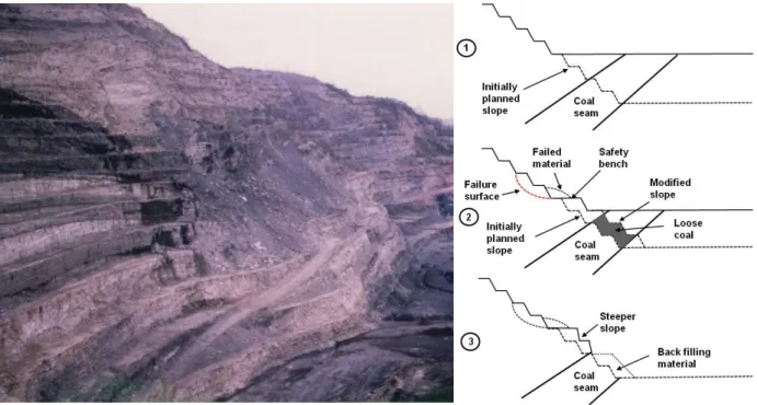
Figure 6 : West slope face of Decazeville coal mine: general view and slope instability (left) and slope management (right)
Unfortunately, when the slope reached a given level of depth, a failure mechanism involving several benches occurred. Field investigations of the failed zone clearly indicated that the dip direction of the layers in this part of the slope changed and became towards the slope dip direction. This change in the geological structure was important enough to explain the failure of the benches, but in any case this failure did not affect the overall stability of the slope face (Figure 6, left and right Nbr 1).
As consequences the mining method was changed and a larger than planned safety bench had to be implemented in order to be able to deepen the pit up to the coal seam. This larger bench however lowered the average overall slope angle with the risk of losing a large volume of coal at the bottom of pit (Figure 6, right Nbr 2).
More detailed investigations and monitoring of this area then showed that the quality of the sandstones mass at the bottom of the slope was rather good. It was slightly jointed and dipping again inside the rock mass. The average slope angle could be locally increased in the lower part of the slope. This made the recovery of the entire volume of coal possible. This was done using a specific mining method: coal was extracted by successive pits with low lateral extension, and after coal mining, the corresponding excavation was immediately back-filed with waste materials acting as a buttress and improving the slope stability (Figure 6, right Nbr 3).
Several conclusions can be drawn from this example: firstly, the importance of the geological structure at different scales on the slope stability control; the absolute necessity to implement a monitoring system of the slope, at least to update the geological structure and check if the data used in the design procedures at the early stages of the mining project remains constant or not.
23 3.2.2 Sar Cheshmeh copper mine in Iran
This is a typical example of a bad slope design resulting from an over-simplification of the geotechnical parameters on the rock material and use of software beyond its own scope and limits.
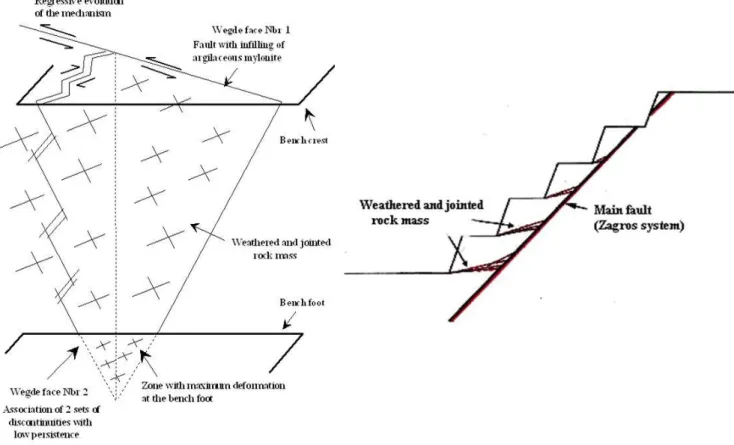
The Sar Cheshmeh mine operates a typical porphyry copper orebody which is intrusive in a siliceous and ferruginous andesite rock mass. According to the genesis of this kind of deposit including various successive stages of hydrothermal and meteoric weathering processes, the geological structure is very complex and exhibits a large variability in lithofacies. Geological and geotechnical conditions radically change from the centre towards the limits of the orebody. The Figure 7 gives a general view of the South-West slope of the pit. It is excavated in highly jointed, silicified and ferruginous andesitic rock mass. Some major faults of Zagros system oriented N160 and dipping 45° towards the North-East (i.e. towards the pit) affects the whole deposit. Several joint sets with low persistence are also present and the rock material itself is highly weathered and jointed.
During the deepening of the pit, important wedge failures involving several 12.5 m high benches occurred as illustrated on the Figure 7. Field observations clearly showed that the first wedge face corresponded to a fault of the Zagros system with mylonite and clayey infilling material, while the second face was formed by the association of two sets of discontinuity with low persistence. The general movement occurred along the intersection line of the two wedge faces, even if the unstable volume was mainly leaning on the first wedge face.
Figure 7 : South west slope of Sar Cheshmeh copper mine in Iran. Overall view and wedge failure mechanism
Standard stability analysis of bench faces or set of benches would consider elementary failure mechanisms such as plane failure along a major fault or wedge failure resulting from the association of a major fault and one or two joint sets. According to the geometrical parameters of the slope and the structural features, such analysis would conclude that these failure mechanisms could be kinematically possible at the scale of one bench, but are absolutely impossible for a set of benches or a whole slope height. As a matter of fact at this scale, the fault or the intersection line of the two planes forming the wedge cannot geometrically
24
daylight in the slope face, because their dip angle is lower than the apparent dip angle of the slope face (Figure 8).
This apparent discrepancy between numerical modelling and reality actually came from the fact that standard analysis of elementary failure mechanisms consider that the rock mass delimited by the discontinuities is a rigid monolith and cannot therefore be deformable. In the present case, the unstable volume delimited by the two wedge faces is itself highly weathered and jointed that makes possible the movement of the mass thanks to strong deformations of the rock mass at the wedge bottom or along a third shear surface through the rock mass.
Figure 8 : Plane or wedge failure mechanism cinematically possible only if the rock material (highly weathered and jointed) can fail.
This example underlines that it is necessary to clearly know the scope of a given software, use it wisely and look for other computational tools when software is no more suitable to the real geological and geomechanical site conditions.
3.2.3 Timbopeba iron ore mine in Brazil
This is a typical example of a slope design problem resulting from the use of software that is not well adapted to potential failure mechanisms predetermined by the geological structure. The Timbopeba iron ore mine operates a hematite and itabirite formation within a southward overturned synclinal structure. The south footwall of the deposit was being excavated in a metamorphic sequence including thick layers of massive banded quartzite overlaid by a 10 m thick zone of interbedded phyllite and quartzite layers forming a quartzite schist with specific structures named almond structures. This name comes from the fact that cross-folding of the units created almond shaped structures as illustrated in Figure 9. The quartzite beds are affected by a few transverse joints. The dip angle of the layers varies between 53 ° and 57 °.
25
Figure 9 : South slope face of the Timbopeba mine in Brazil: bilinear slab potential failure mechanism
The south pit side was excavated without any benches because they would be unstable due to obvious risks of plane failure along the schistosity planes. The overall slope stability was a main concern of the mining company which was planning to deepen the pit from 175 m up to 300 m.
Various failure mechanisms had been tested by different geotechnical consultants, and particularly standard failure mechanism along a polygonal failure surface following the banded quartzite schistosity planes parallel to the slope face (footwall situation) and daylighting at the toe of the slope using a discontinuity through the rock mass. If the shape of the surface was correct, the software used for the calculation of the factor of safety used a numerical technique suitable to deep seated polygonal failure surface in soil mechanics (slice method) which was not appropriate for rock material. The results were very alarmist because the factor of safety obtained with the method were equal to 0.60 (considering the lowest value of cohesion and angle of friction for the various discontinuity sets and the rock material, but without any water pressure in the rock mass), and the consultants consequently required the mine closure and the urgent implementation of mechanical reinforcements.
But field inspections of the toe and top of the slope did not show any specific sign of instability and topographic survey did not show any displacement of the overall slope. Moreover, the slope already experienced blasting vibrations and heavy rain falls for several years without any stability problem. How a slope with a factor of safety of 0.60 could still stand?
The obvious conclusion was that the selected failure mechanism and corresponding numerical technique was not appropriate. In such footwall situation, other failure mechanisms such as bilinear or buckling slab failures illustrated in Figure 4 are more realistic. For such mechanisms, the stability analysis is carried out by dividing the potentially unstable mass into an active or driving block and a passive or resisting block located at the toe of the slope. Considering the freebody diagram of the two blocks, the factor of safety is calculated by
26
analysing the equilibrium of the toe block acting as a key block for the upper volume of the slope (Figure 9). The implementation of such failure mechanism led to value of factor of safety equal to 1.60 for the same geological, mechanical and hydraulic parameters, in better agreement with the field observation.
The project which was planning to deepen the pit up to 300 m could be continued provided however to improve the geological investigation in depth, to consider drainage works and maybe local mechanical reinforcement, and to develop the monitoring system of the slope. The pit, now depleted, reached a total depth of 350 m without any major stability problem.
4. Particular case of waste embankments
The term of waste embankment includes both rock or soil waste dump and tailing dams. The primary function of waste embankment is to store the waste material from mining operations in a given area and to ensure safety of people and equipment during the construction phases, as well as safety of inhabited sites eventually located in the immediate neighbourhood of the disposal.
Waste dumps are defined as waste disposals resulting directly from mine excavation operations. They contain soil or rock material placed on surface close to the mining site utilising dry process.
Tailing dams are formed with waste resulting from ore processing plants after crushing, grinding and physical or chemical processing. They retain tailings in slurry form stocked in reservoirs behind dams which may be constructed of either coarser part of tailings and waste rock or natural soil of combination of these materials.
The design specifications discussed in this document mainly deal with issue of stability, with some considerations on the effects of surface water run-off and groundwater. The main parameters considered in embankment stability are related to strength of both waste materials and potentially weak foundation materials, embankment geometry including height and maximum slope angle that will ensure the long term stability even after the end of the mining operations, and appropriate water drainage systems to prevent softening of the embankment, internal erosion leading to breaching, and water overflow of tailing dams.
Of course possible water pollution by natural or processing-induced contaminant elements contained in the waste as well as reclamation aspects should be considered and could lead to additional design provisions.
In addition, other issues have to be kept in mind, including changes to the material properties due to chemical weathering / chemical reaction / leaching such as changes in permeability of clay liner. Static liquefaction triggered by rise in water table, blasting or seismic event have to be considered. Changes in stress conditions due to construction, excavation, seepage and erosion have to be noted down.